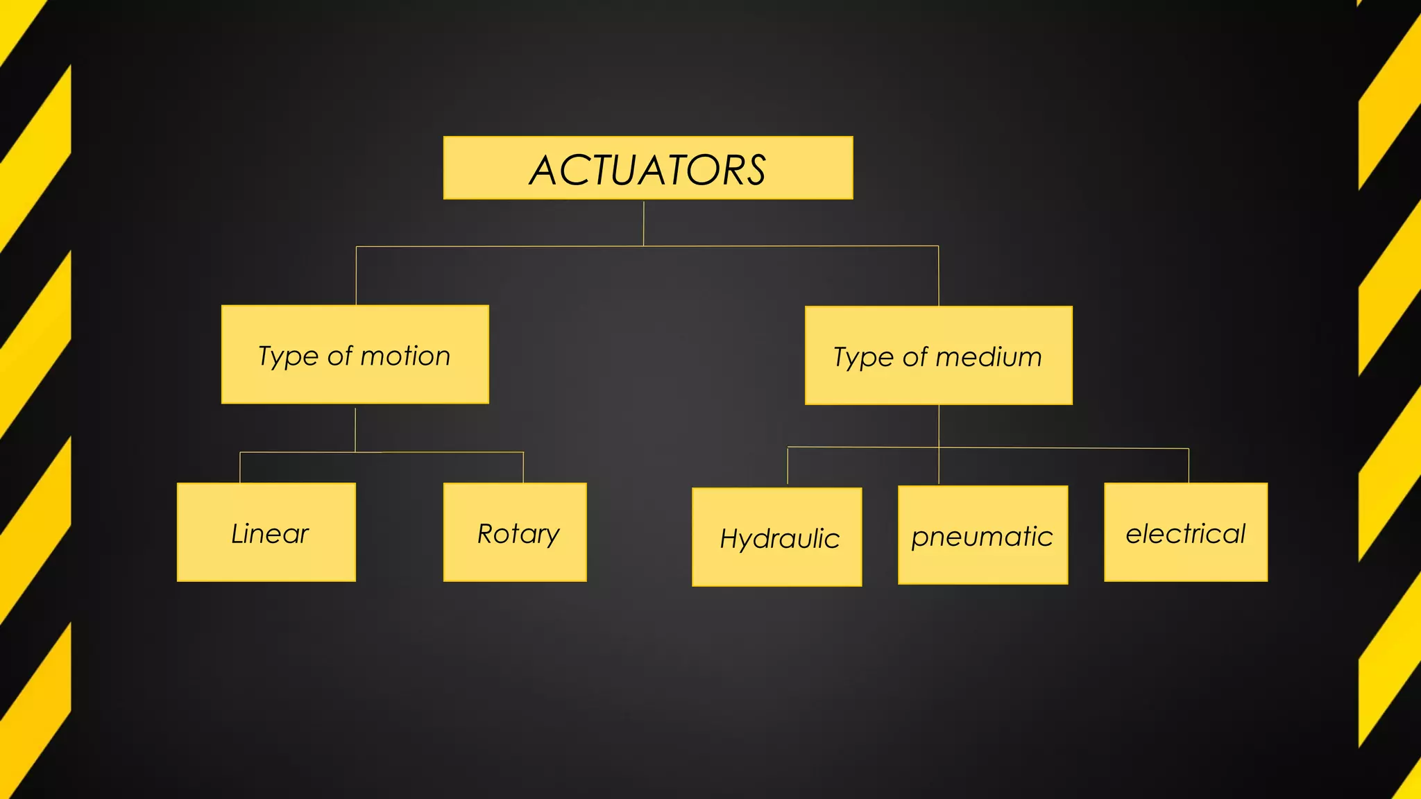
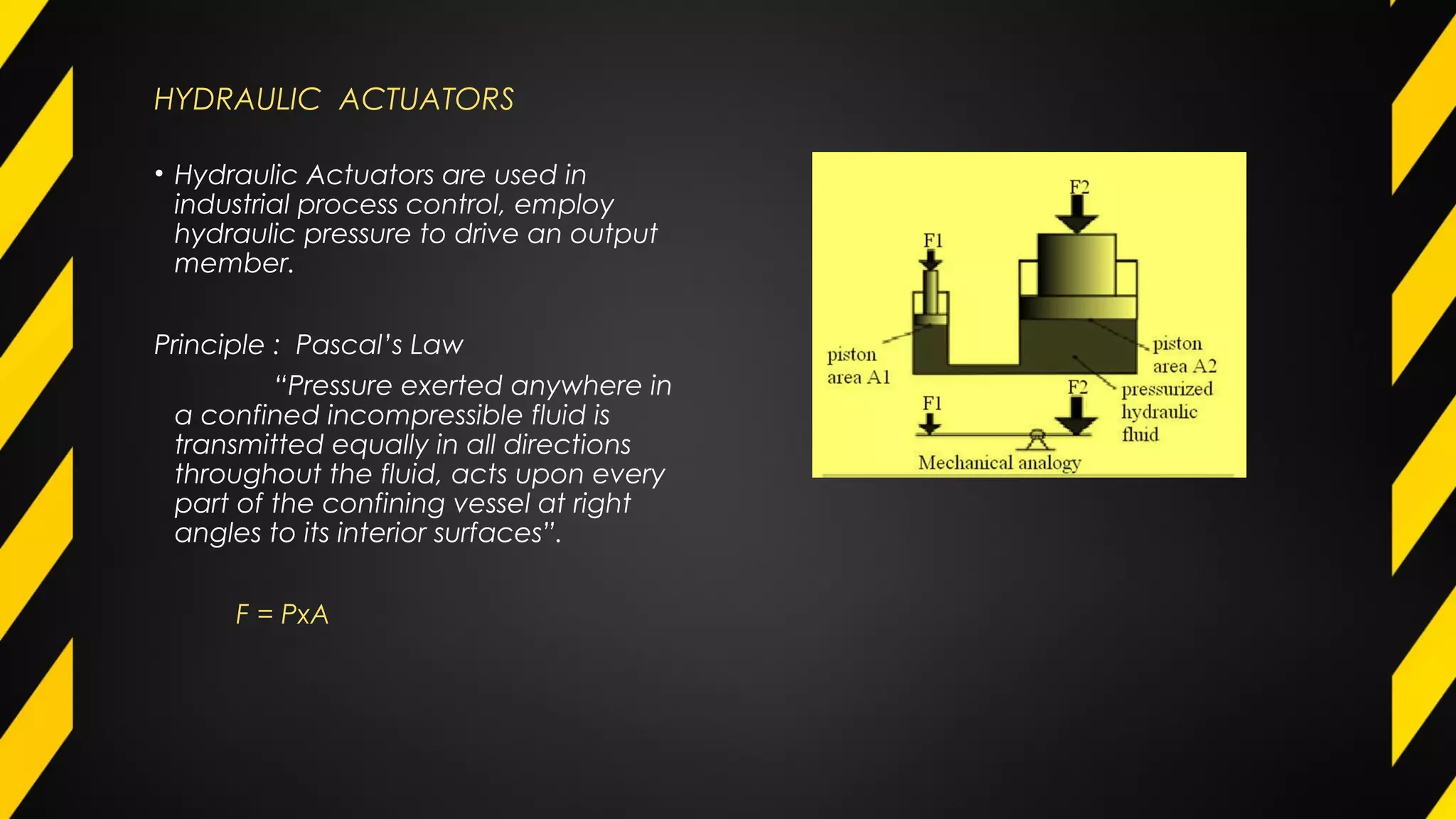
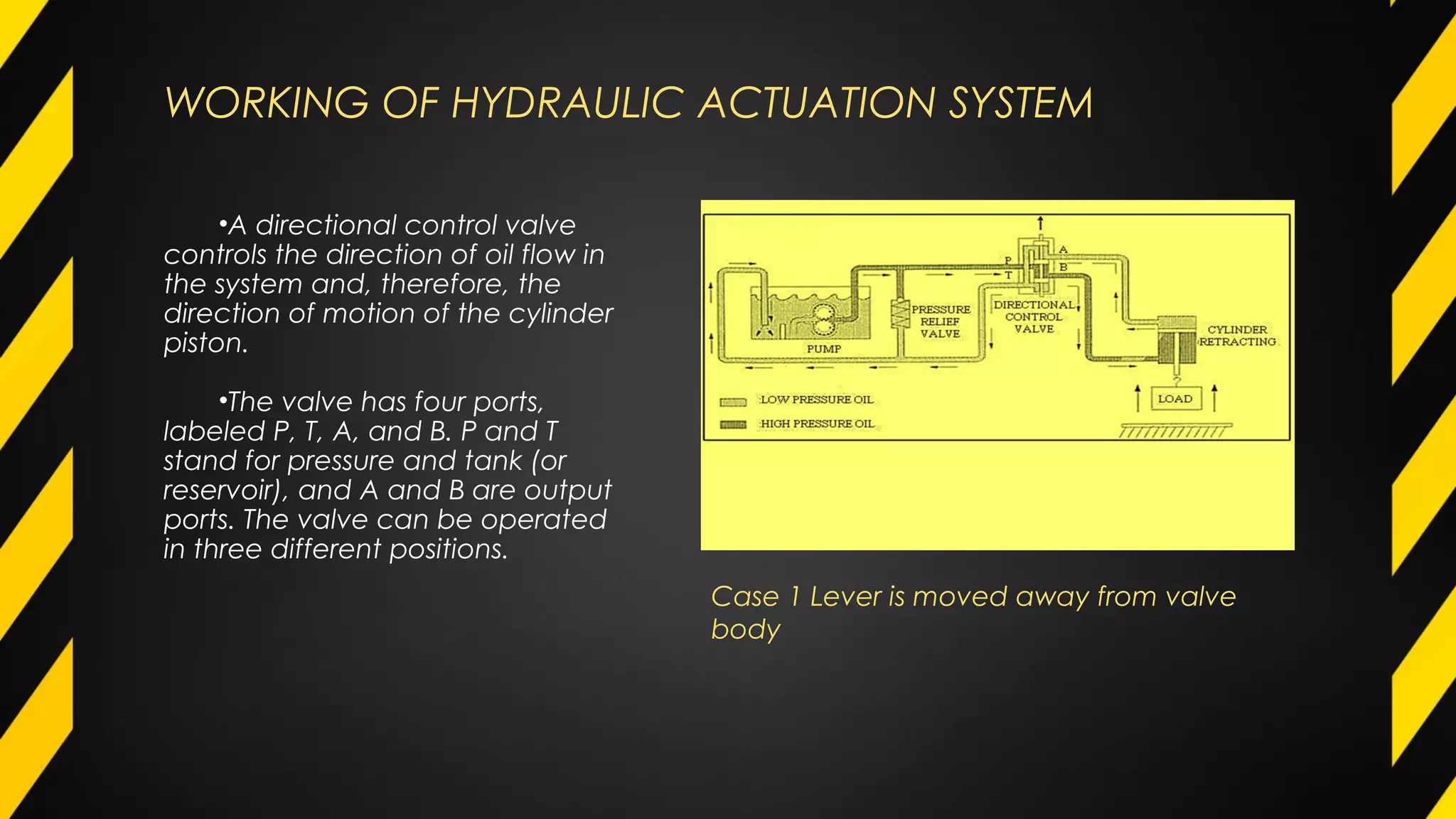
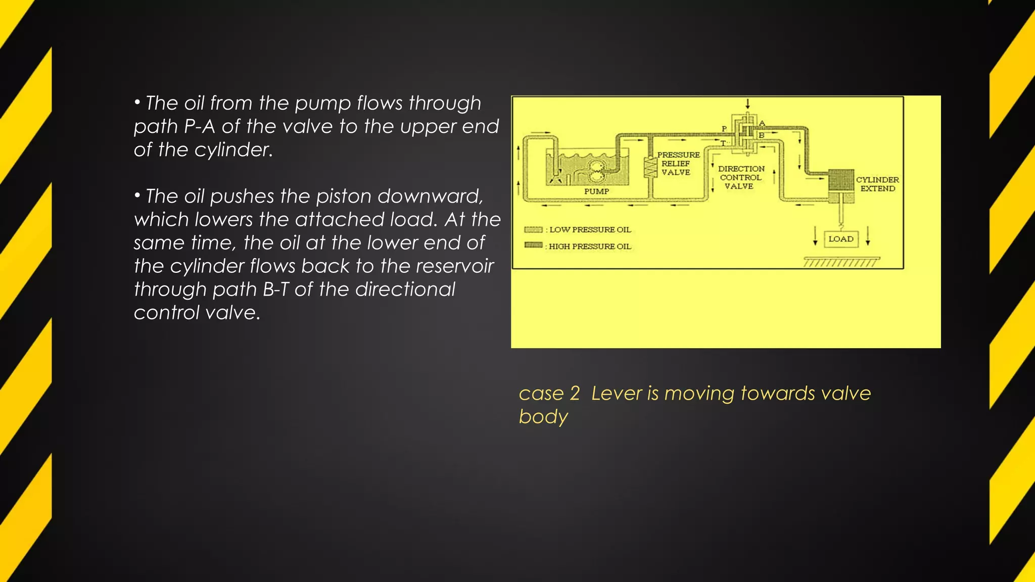
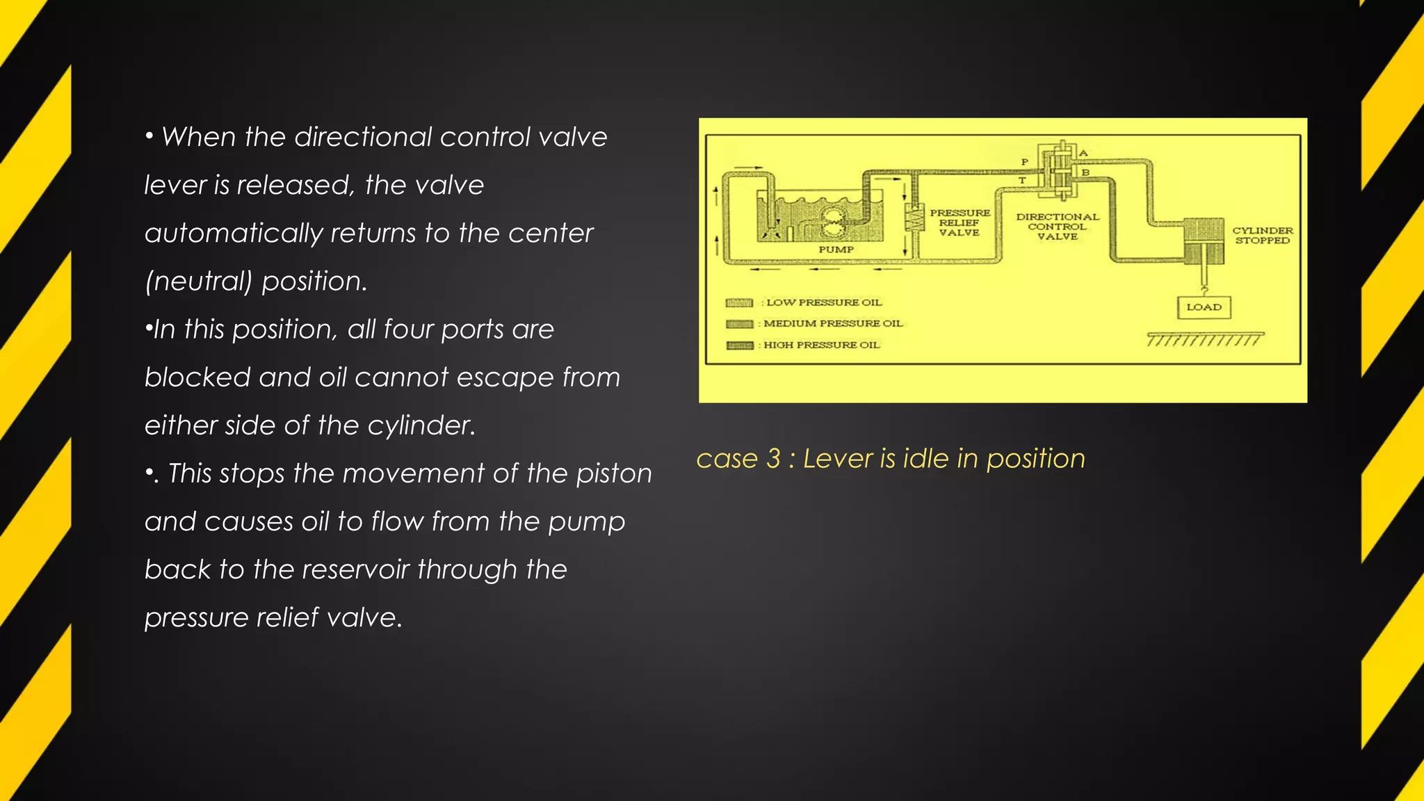
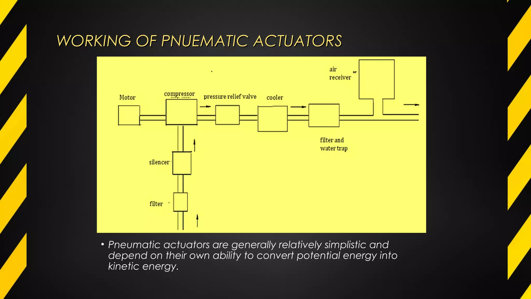
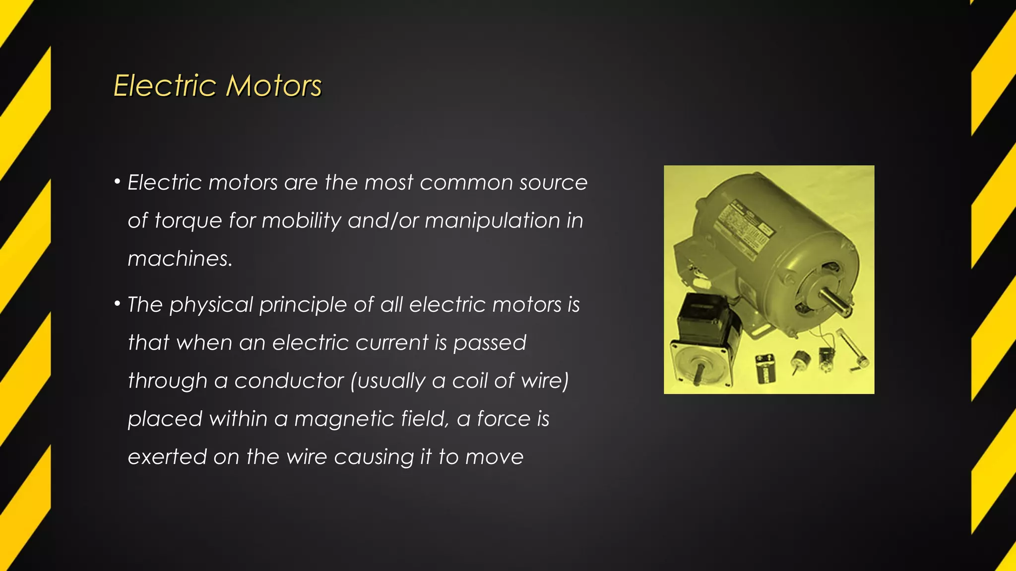
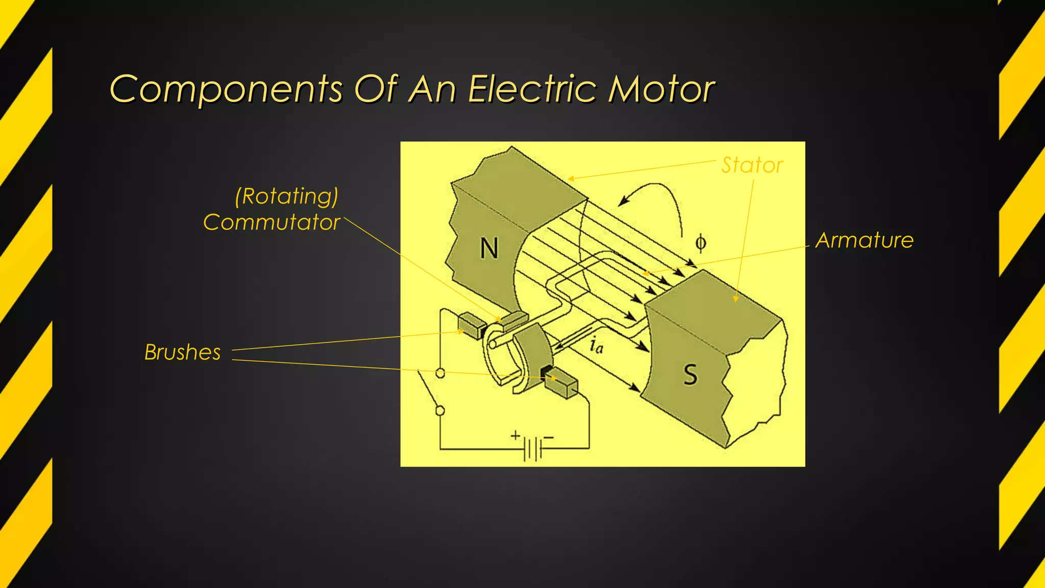
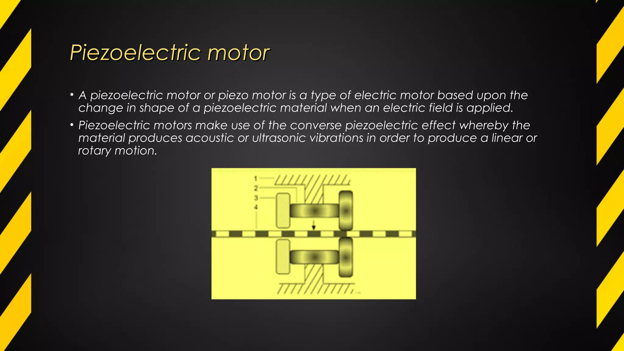
Various types of actuatorsVarious types of actuatorsVarious types of actuatorsVarious types of actuators
Type of motion
Linear Rotary
Type of medium
Hydraulic pneumatic electrical
ACTUATORS
HYDRAULIC ACTUATORS
• Hydraulic Actuators are used in
industrial process control, employ
hydraulic pressure to drive an output
member.
Principle : Pascal’s Law
“Pressure exerted anywhere in
a confined incompressible fluid is
transmitted equally in all directions
throughout the fluid, acts upon every
part of the confining vessel at right
angles to its interior surfaces”.
F = PxA
WORKING OF HYDRAULIC ACTUATION SYSTEM
•Α directional control valve
controls the direction of oil flow in
the system and, therefore, the
direction of motion of the cylinder
piston.
•The valve has four ports,
labeled Ρ, Τ, Α, and Β. Ρ and Τ
stand for pressure and tank (or
reservoir), and Α and Β are output
ports. The valve can be operated
in three different positions.
Case 1 Lever is moved away from valve
body
case 2 Lever is moving towards valve
body
• The oil from the pump flows through
path Ρ-Α of the valve to the upper end
of the cylinder.
• The oil pushes the piston downward,
which lowers the attached load. At the
same time, the oil at the lower end of
the cylinder flows back to the reservoir
through path Β-Τ of the directional
control valve.
case 3 : Lever is idle in position
• When the directional control valve
lever is released, the valve
automatically returns to the center
(neutral) position.
•In this position, all four ports are
blocked and oil cannot escape from
either side of the cylinder.
•. This stops the movement of the piston
and causes oil to flow from the pump
back to the reservoir through the
pressure relief valve.
PNEUMATIC ACTUATOR
• A pneumatic actuator converts energy (typically in the form of compressed Air) into
motion. The motion can be rotary or linear, depending on the type of actuator.
• A Pneumatic actuator mainly consists of a piston, a cylinder, and valves or ports.
• Pneumatic systems are very common, and have much in common with hydraulic
systems with a few key differences
WORKING OF PNUEMATIC ACTUATORS WORKING OF PNUEMATIC ACTUATORS 
• Pneumatic actuators are generally relatively simplistic and
depend on their own ability to convert potential energy into
kinetic energy.
Electric MotorsElectric Motors
• Electric motors are the most common source
of torque for mobility and/or manipulation in
machines.
• The physical principle of all electric motors is
that when an electric current is passed
through a conductor (usually a coil of wire)
placed within a magnetic field, a force is
exerted on the wire causing it to move
Components Of An Electric MotorComponents Of An Electric Motor
The principle components of an electric motor are:
•North and south magnetic poles to provide a strong magnetic field. Being made
of bulky ferrous material they traditionally form the outer casing of the motor and
collectively form the stator
•An armature, which is a cylindrical ferrous core rotating within the stator and
carries a large number of windings made from one or more conductors
Components Of An Electric MotorComponents Of An Electric Motor
• A commutator, which rotates with the armature and consists of copper contacts
attached to the end of the windings
• Brushes in fixed positions and in contact with the rotating commutator contacts.
They carry direct current to the coils, resulting in the required motion
Components Of An Electric MotorComponents Of An Electric Motor
(Rotating)
Commutator
Stator
Brushes
Armature
How Do Electric MotorsHow Do Electric Motors Work?Work?
• The classic DC motor has a rotating armature in the form of an electromagnet
• A rotary switch called a commutator reverses the direction of the electric current
twice every cycle, to flow through the armature so that the poles of the
electromagnet push and pull against the permanent magnets on the outside of the
motor
• As the poles of the armature electromagnet pass the poles of the permanent
magnets, the commutator reverses the polarity of the armature electromagnet.
• During that instant of switching polarity, inertia keeps the motor going in the proper
direction
Piezoelectric motorPiezoelectric motor
• A piezoelectric motor or piezo motor is a type of electric motor based upon the
change in shape of a piezoelectric material when an electric field is applied.
• Piezoelectric motors make use of the converse piezoelectric effect whereby the
material produces acoustic or ultrasonic vibrations in order to produce a linear or
rotary motion.
BIMORPHBIMORPH
• A bi-laminar actuator is made from a piezoelectric smart material that returns to its
original shape after a force is to applied to it.
• “A flexing or bending actuator is designed to produce a relatively large mechanical
deflection in response to an electrical signal.”
• “Two thin strips of piezoelectric ceramic are bonded together, usually with the
direction of polarization coinciding, and are electrically connected in parallel.”
Basic Working PrincipleBasic Working Principle
• “When electrical input is applied, one ceramic layer expands and the other
contracts, causing the actuator to flex.”
+ - + -
Vin>0V
Vin=0V
MEMS ACTUATORSMEMS ACTUATORS
Thermal Actuators
V-Shaped Thermal Actuators
These actuators are based on the constrained thermal expansion of
the angled beams (a result of Joule heating when a current is passed through the legs
of the actuator), resulting in motion of the centre shuttle in the direction shown by
the arrow in the figure.
Electrostatic ActuatorsElectrostatic Actuators
Torsional Ratcheting Actuator (TRA)Torsional Ratcheting Actuator (TRA)
Electrostatic ActuatorsElectrostatic Actuators
Skillcruise.com

Various types of actuators

  • 1.
    Various types ofactuatorsVarious types of actuatorsVarious types of actuatorsVarious types of actuators
  • 2.
    Type of motion LinearRotary Type of medium Hydraulic pneumatic electrical ACTUATORS
  • 3.
    HYDRAULIC ACTUATORS • HydraulicActuators are used in industrial process control, employ hydraulic pressure to drive an output member. Principle : Pascal’s Law “Pressure exerted anywhere in a confined incompressible fluid is transmitted equally in all directions throughout the fluid, acts upon every part of the confining vessel at right angles to its interior surfaces”. F = PxA
  • 4.
    WORKING OF HYDRAULICACTUATION SYSTEM •Α directional control valve controls the direction of oil flow in the system and, therefore, the direction of motion of the cylinder piston. •The valve has four ports, labeled Ρ, Τ, Α, and Β. Ρ and Τ stand for pressure and tank (or reservoir), and Α and Β are output ports. The valve can be operated in three different positions. Case 1 Lever is moved away from valve body
  • 5.
    case 2 Leveris moving towards valve body • The oil from the pump flows through path Ρ-Α of the valve to the upper end of the cylinder. • The oil pushes the piston downward, which lowers the attached load. At the same time, the oil at the lower end of the cylinder flows back to the reservoir through path Β-Τ of the directional control valve.
  • 6.
    case 3 :Lever is idle in position • When the directional control valve lever is released, the valve automatically returns to the center (neutral) position. •In this position, all four ports are blocked and oil cannot escape from either side of the cylinder. •. This stops the movement of the piston and causes oil to flow from the pump back to the reservoir through the pressure relief valve.
  • 7.
    PNEUMATIC ACTUATOR • A pneumaticactuator converts energy (typically in the form of compressed Air) into motion. The motion can be rotary or linear, depending on the type of actuator. • A Pneumatic actuator mainly consists of a piston, a cylinder, and valves or ports. • Pneumatic systems are very common, and have much in common with hydraulic systems with a few key differences
  • 8.
    WORKING OF PNUEMATICACTUATORS WORKING OF PNUEMATIC ACTUATORS  • Pneumatic actuators are generally relatively simplistic and depend on their own ability to convert potential energy into kinetic energy.
  • 9.
    Electric MotorsElectric Motors •Electric motors are the most common source of torque for mobility and/or manipulation in machines. • The physical principle of all electric motors is that when an electric current is passed through a conductor (usually a coil of wire) placed within a magnetic field, a force is exerted on the wire causing it to move
  • 10.
    Components Of AnElectric MotorComponents Of An Electric Motor The principle components of an electric motor are: •North and south magnetic poles to provide a strong magnetic field. Being made of bulky ferrous material they traditionally form the outer casing of the motor and collectively form the stator •An armature, which is a cylindrical ferrous core rotating within the stator and carries a large number of windings made from one or more conductors
  • 11.
    Components Of AnElectric MotorComponents Of An Electric Motor • A commutator, which rotates with the armature and consists of copper contacts attached to the end of the windings • Brushes in fixed positions and in contact with the rotating commutator contacts. They carry direct current to the coils, resulting in the required motion
  • 12.
    Components Of AnElectric MotorComponents Of An Electric Motor (Rotating) Commutator Stator Brushes Armature
  • 13.
    How Do ElectricMotorsHow Do Electric Motors Work?Work? • The classic DC motor has a rotating armature in the form of an electromagnet • A rotary switch called a commutator reverses the direction of the electric current twice every cycle, to flow through the armature so that the poles of the electromagnet push and pull against the permanent magnets on the outside of the motor • As the poles of the armature electromagnet pass the poles of the permanent magnets, the commutator reverses the polarity of the armature electromagnet. • During that instant of switching polarity, inertia keeps the motor going in the proper direction
  • 14.
    Piezoelectric motorPiezoelectric motor •A piezoelectric motor or piezo motor is a type of electric motor based upon the change in shape of a piezoelectric material when an electric field is applied. • Piezoelectric motors make use of the converse piezoelectric effect whereby the material produces acoustic or ultrasonic vibrations in order to produce a linear or rotary motion.
  • 15.
    BIMORPHBIMORPH • A bi-laminaractuator is made from a piezoelectric smart material that returns to its original shape after a force is to applied to it. • “A flexing or bending actuator is designed to produce a relatively large mechanical deflection in response to an electrical signal.” • “Two thin strips of piezoelectric ceramic are bonded together, usually with the direction of polarization coinciding, and are electrically connected in parallel.”
  • 16.
    Basic Working PrincipleBasicWorking Principle • “When electrical input is applied, one ceramic layer expands and the other contracts, causing the actuator to flex.” + - + - Vin>0V Vin=0V
  • 17.
    MEMS ACTUATORSMEMS ACTUATORS ThermalActuators V-Shaped Thermal Actuators These actuators are based on the constrained thermal expansion of the angled beams (a result of Joule heating when a current is passed through the legs of the actuator), resulting in motion of the centre shuttle in the direction shown by the arrow in the figure.
  • 18.
    Electrostatic ActuatorsElectrostatic Actuators TorsionalRatcheting Actuator (TRA)Torsional Ratcheting Actuator (TRA)
  • 19.
  • 20.