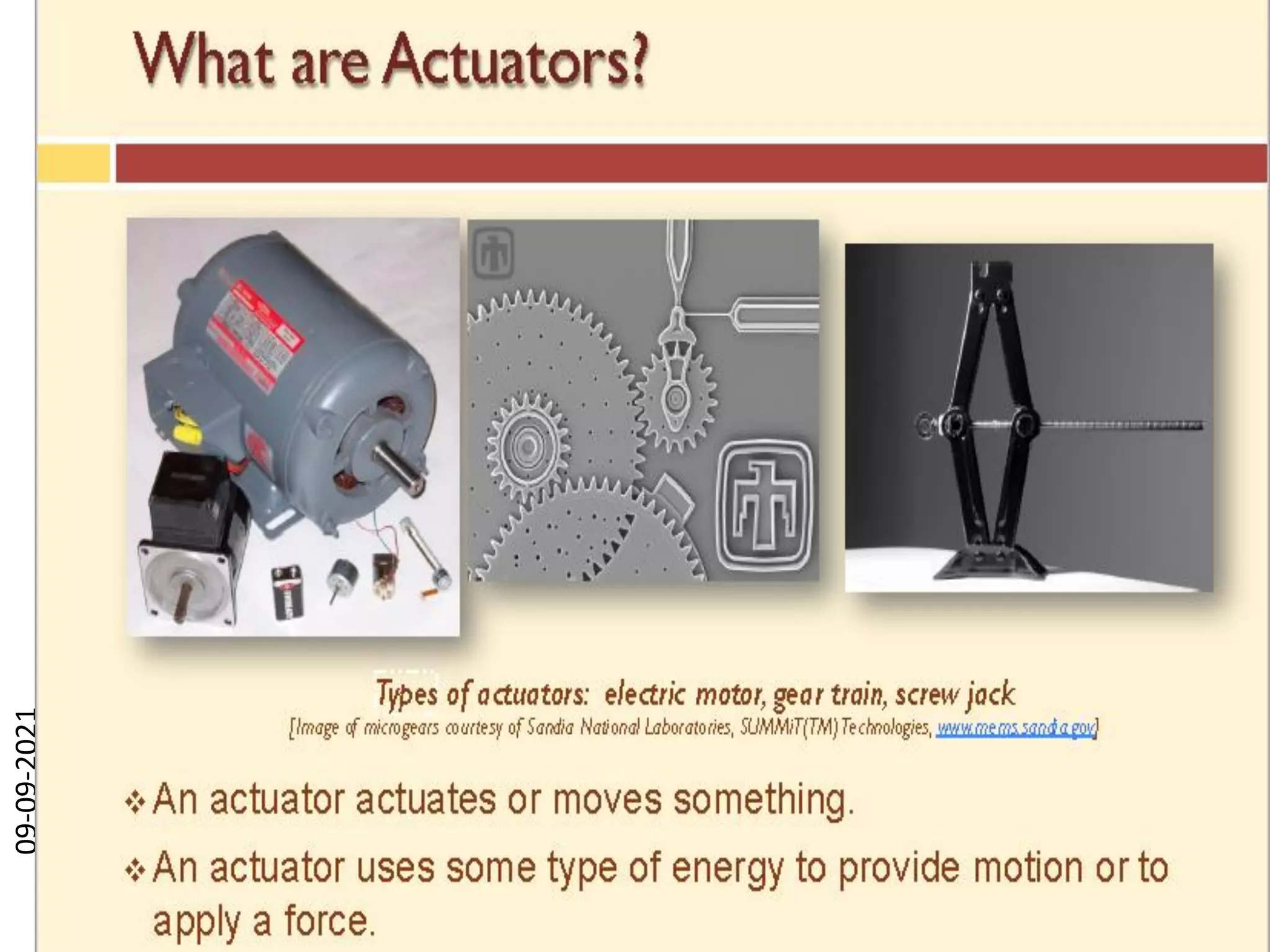
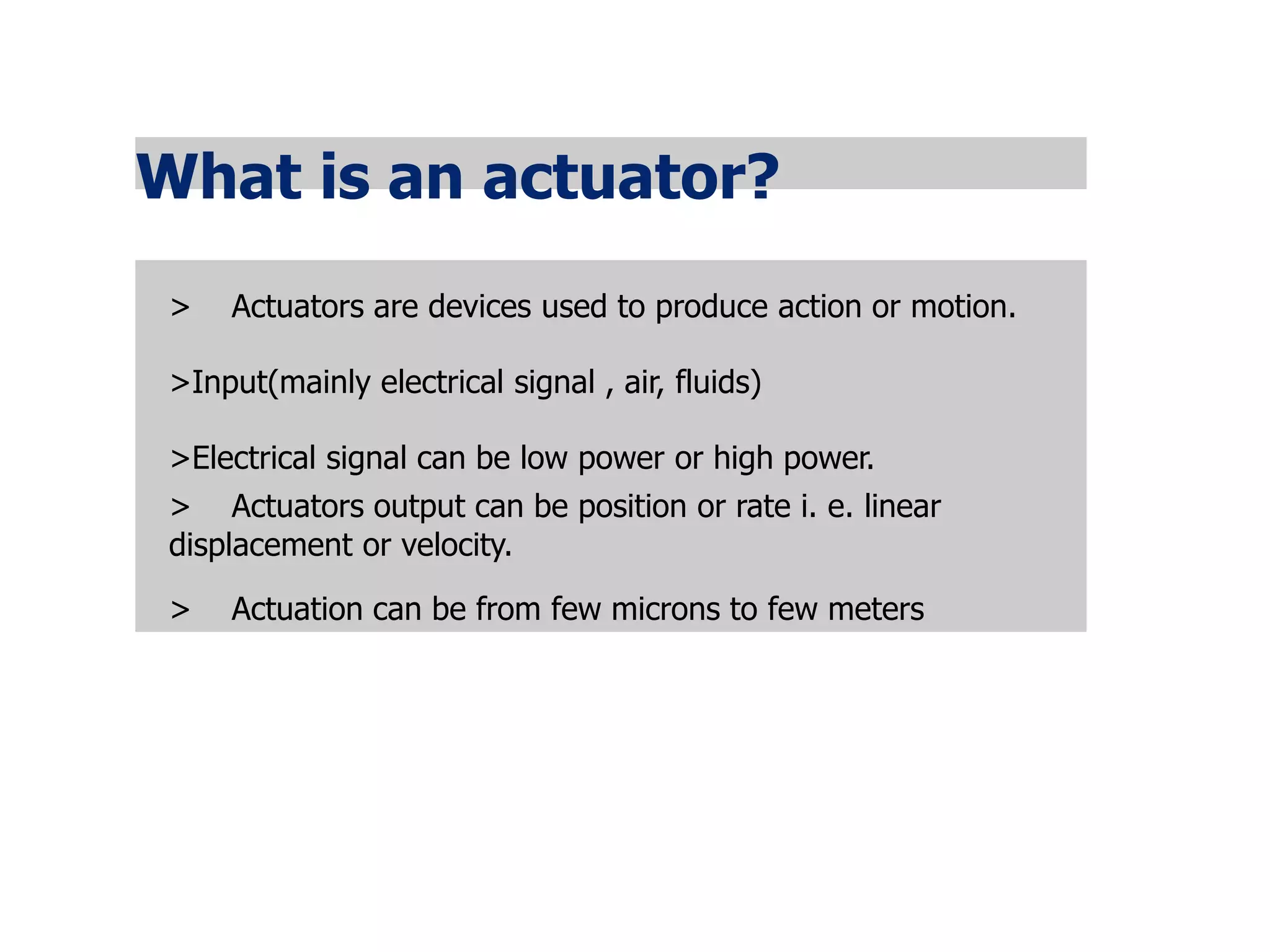
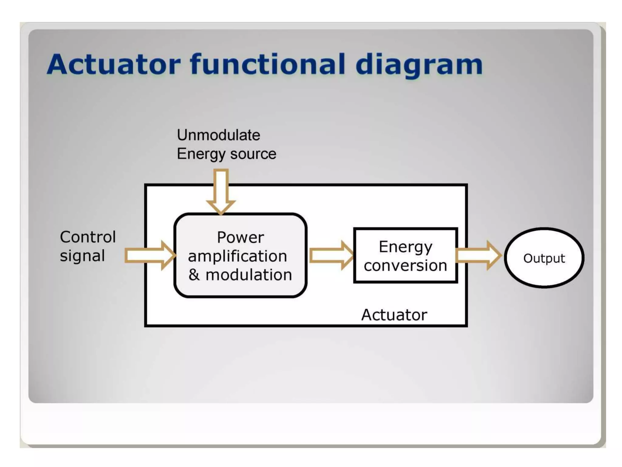
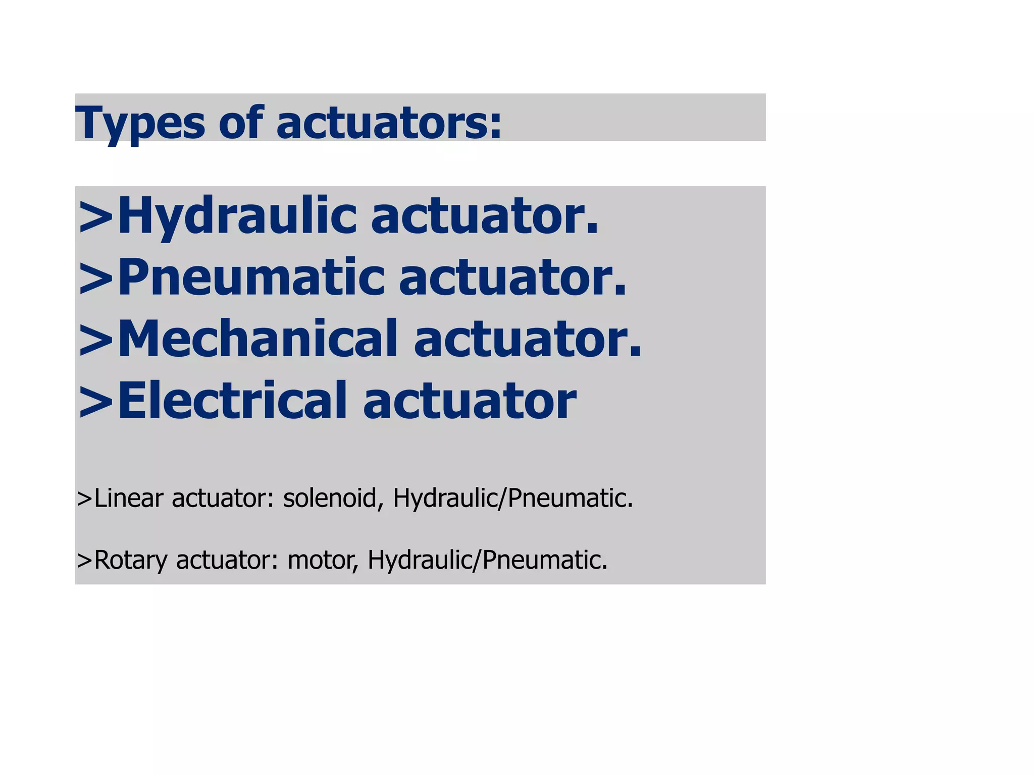
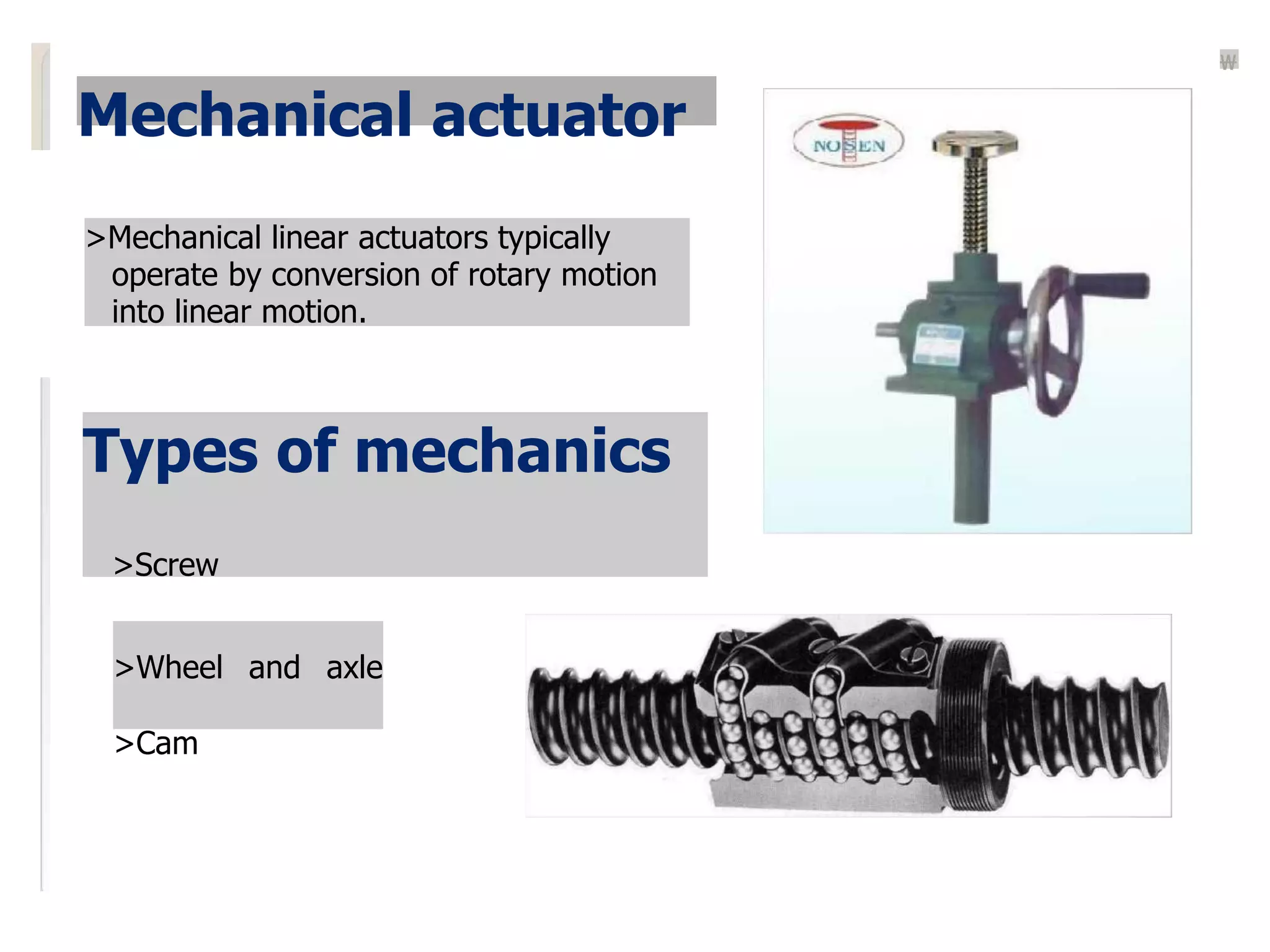
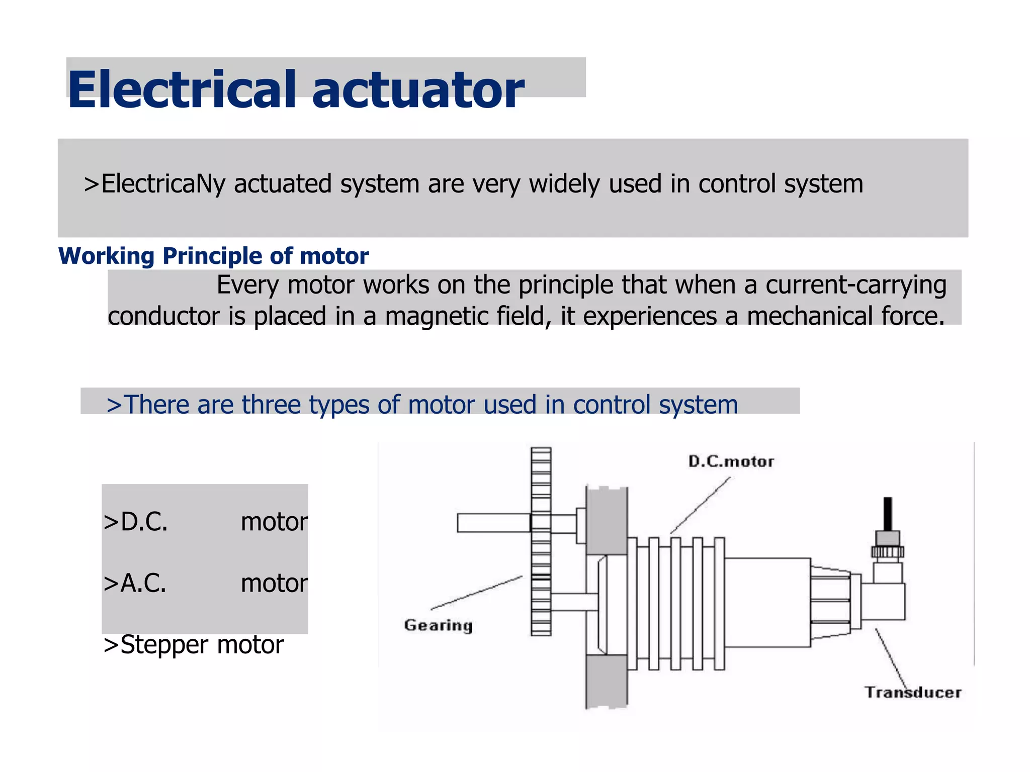
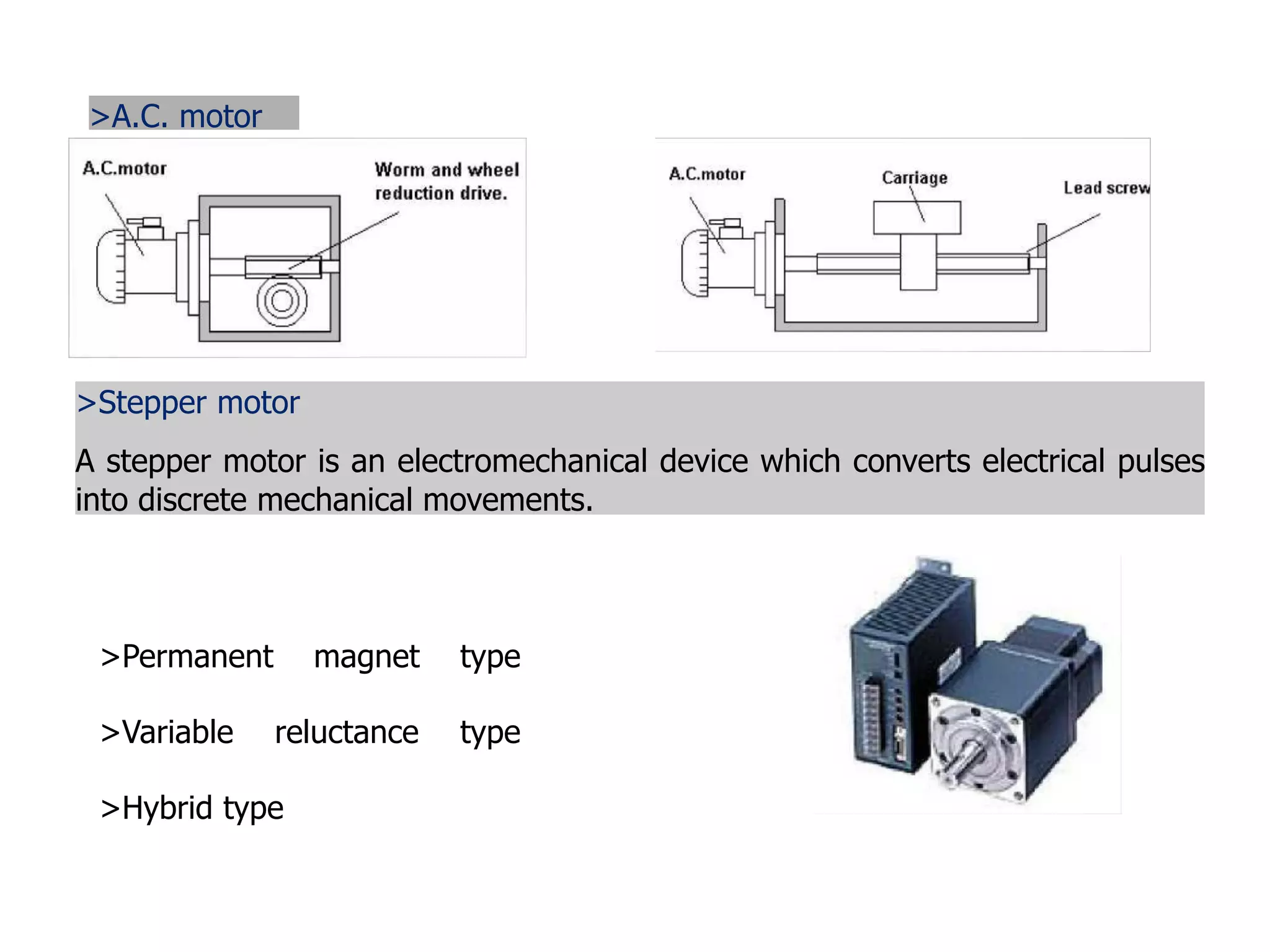
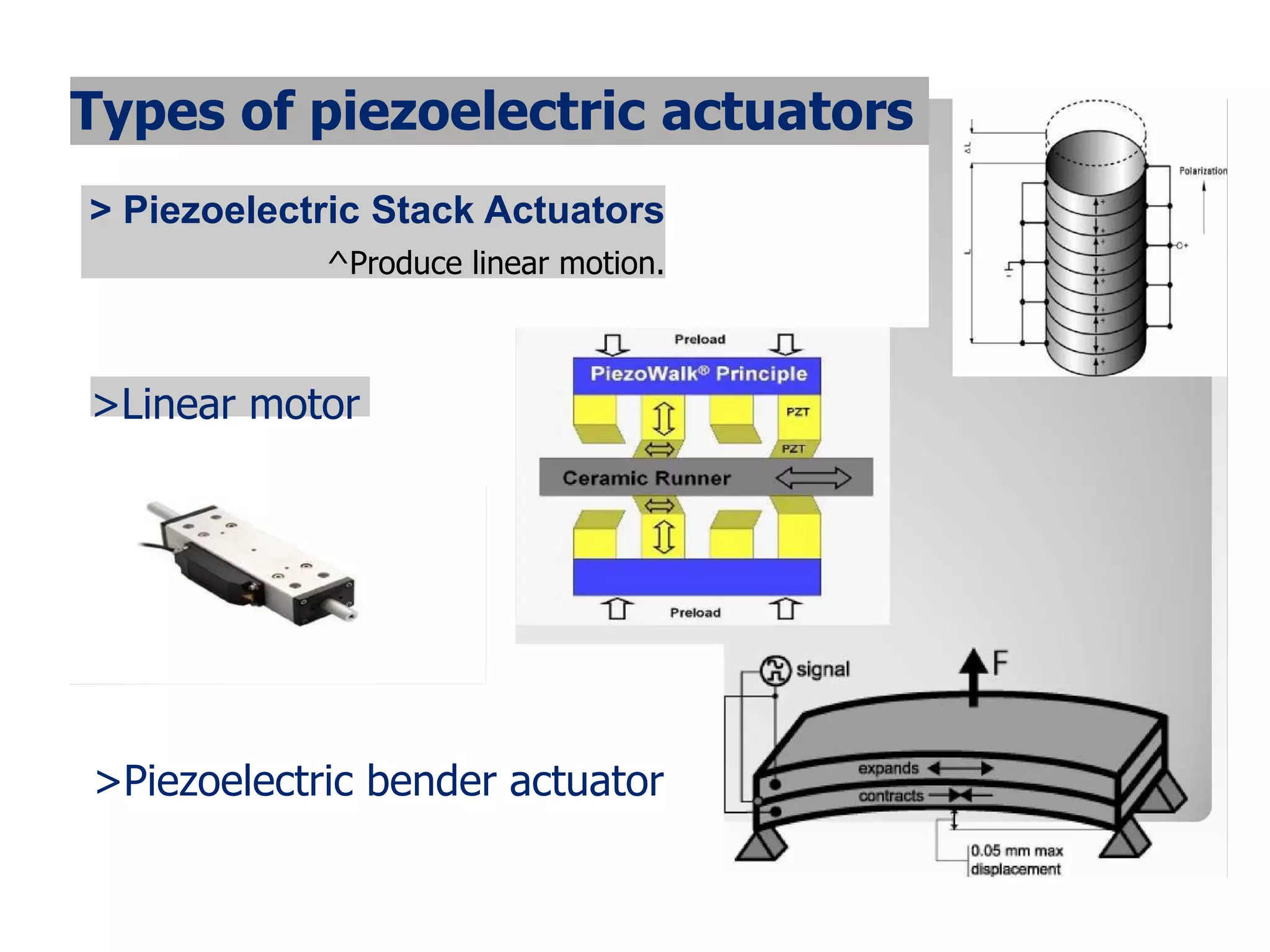
LECTURE-1
 INTRODUCTION TO ACTUATORS
UNIT 2
• An actuator is a component of a machine that is
responsible for moving and controlling a
mechanism or system
(OR)
• An actuator is a device that uses a form of power to
convert a control signal into mechanical motion.
09-09-2021
3
09-09-2021
4
• An actuator requires a control signal and a source of
energy.
• The control signal is relatively low energy and may be
electric voltage or current, pneumatic or hydraulic
pressure, or even human power.
• Its main energy source may be an electric current,
hydraulic fluid pressure, or pneumatic pressure. When it
receives a control signal, an actuator responds by
converting the source's energy into mechanical motion.
• An actuator is the mechanism by which a control system
acts upon an environment. The control system can be
simple (a fixed mechanical or electronic system), software-
based (e.g. a printer driver, robot control system), a human,
or any other input.[
09-09-2021
5
What is an actuator?
> Actuators are devices used to produce action or motion.
>Input(mainly electrical signal , air, fluids)
>Electrical signal can be low power or high power.
> Actuators output can be position or rate i. e. linear
displacement or velocity.
> Actuation can be from few microns to few meters
Types of actuators:
>Hydraulic actuator.
>Pneumatic actuator.
>Mechanical actuator.
>Electrical actuator
>Linear actuator: solenoid, Hydraulic/Pneumatic.
>Rotary actuator: motor, Hydraulic/Pneumatic.
>A solenoid is a coil wound into a tightly packed helix.
>In physics, the term solenoid refers to a long, thin loop of wire,
and wrapped around a metallic core.
>which produces a magnetic field when an electric current is
passed through it.
Application
^Pneumatic valve.
>Car door openers.
Solenoids controlled valves
Single pressure line
Hydraulic actuator:
>Hydraulic systems are used to control & transmit power.
>A pump driven by prime mover (electric motor) creates flow of fluid
Types of hydraulic actuator
Linear actuator (hydraulic cylinder)-
>Provides motion in straight line.
>Linear displacement depends on stroke length.
>Usually referred to as cylinders, rams (single acting cylinders) or jacks.
Rotary actuators (Hydraulic motors)-
>Produces continuous rotational motion.
>Pump shaft is rotated to generate flow.
>A motor shaft is caused to rotate by fluid being forced into the driving
chambers.
Semi rotary actuators-
>Produces non-continuous rotational motion. >Limited to
less than one revolution (<360°).
>Used to produce oscillatory motions in mechanisms.
Applications
^Hydraulic jack.
^Hydraulic brake.
^Hydraulic ram.
>Used as sensor.
>Close loop velocity controlling.
>Highly precise positioning for heavy loads.
Pneumatic actuator
>It convert energy formed by compressed air at high pressure into
ether linear or rotary motion.
>Quickly respond in operation.
CONSTRUCTIONAL FEATURES OF CYLINDER
Hydraulic & pneumatic actuators: cylinders
Single acting:
work can be done only in one
direction
Plunger
Piston
Telescopic
Double acting piston
Work is done in both directions
Piston rod on both sides
Tandem
Telescopic
■
10
Double acting cylinder with & without cushioning
>Non cushioned cylinders are suitable for full stroke working at slow speed.
>Higher speeds with external cushions.
i
s cushioning & c a l
p ii(On iaalS
Rotary hydraulic actuators
Vane rotary actuator:
> Limited angle in both directions.
> Maximum angle always smaller than
360°
> The same torque in both directions.
Parallel
piston
rotary
actuator
Limited angle
rotary actuator
Piston rotary actuator:
Limited angle rotary
actuator
> With rack and gear coupling.
> Here maximum angle may be larger than
360°
12
Mechanical actuator
>Mechanical linear actuators typically
operate by conversion of rotary motion
into linear motion.
Types of mechanics
>Screw
>Wheel and axle
>Cam
Electrical actuator
>ElectricaNy actuated system are very widely used in control system
Working Principle of motor
Every motor works on the principle that when a current-carrying
conductor is placed in a magnetic field, it experiences a mechanical force.
>There are three types of motor used in control system
>D.C. motor
>A.C. motor
>Stepper motor
>A.C. motor
>Stepper motor
A stepper motor is an electromechanical device which converts electrical pulses
into discrete mechanical movements.
>Permanent magnet type
>Variable reluctance type
>Hybrid type
Piezoelectric actuators
> Pierre and Jacques Curie discovered the piezoelectric effect in 1880.
>The application of an electric field to a piezoelectric crystal leads to a
physical deformation of the crystal.
> Piezoelectric materials are: Quartz, Ceramics, PZT(lead zirconate
titanade).
^Advantages
>short response time.
>An ability to create high forces.
>A high efficiency and a high mechanical durability.
> Disadvantage
>Have small strains. (0.1-.2%)
>High supply voltage needed.(60-1000V)
> Large hysteresis.(actuator doesn’t go back to exactly where it started).
Configuration
> A piezo ceramic crystal is coated with silver on both sides.
> Glued to a brass, nickel alloy, or stainless steel disk.
> Brass:
^Commercial & industrial use.(not subjected to environment
) >Nickel alloy:
>Use where it subjected to environment.
> Stainless steel:
>Uses where it subjected to solvent, corrosive chemical,
Underwater .
>Medical fields.
Types of piezoelectric actuators
> Piezoelectric Stack Actuators
^Produce linear motion.
>Linear motor
>Piezoelectric bender actuator
Other type of actuator
Heaters - used with temperature sensors And temperature controller
to control the temperature in automated moulding Equipment and in soldering
operation.
Lights - Lights are used on almost all machines to indicate the machine state
and provide feedback to the operator.
>LED > LCD's
>Gas plasma display >CRT
Sirens/Horns - Sirens or horns can be useful for unattended or dangerous
machines to make conditions well known.
LECTURE-2
 STEPPER MOTOR
 SERVO MOTOR
STEPPER MOTOR
INTRODUCTION
A stepper motor or step motor or stepping
motor is a brushless DC electric motor that
divides a full rotation into a number of equal
steps.
The motor's position can then be commanded
to move and hold at one of these steps
without any position sensor for feedback (an
open-loop controller), as long as the motor is
carefully sized to the application in respect to
torque and speed.
What is a stepper motor?
The stepper motor is an electromagnetic
device that converts digital pulses into
mechanical shaft rotation.
A servomotor is a rotary actuator or linear
actuator that allows for precise control of
angular or linear position, velocity and
acceleration
What is a stepper motor?
Stepper motors are DC motors that move in
discrete steps.
They have multiple coils that are organized in
groups called "phases".
By energizing each phase in sequence, the
motor will rotate, one step at a time.
With a computer controlled stepping you can
achieve very precise positioning and/or speed
control.
Why stepper motor is used?
Stepper motors are versatile, brushless,
synchronous motors that are widely used in a
variety of applications.
Because stepper motors can move in
accurate, discrete angular increments (steps)
in reaction to electrical input pulses, they are
ideal for applications that require controlled,
precise movements.
How Stepper Motors Work?
 Stepper motors consist of a permanent magnetic
rotating shaft, called the rotor, and electromagnets on
the stationary portion that surrounds the motor, called
the stator.
 Figure illustrates one complete rotation of a stepper
motor.
 At position 1, we can see that the rotor is beginning at
the upper electromagnet, which is currently active (has
voltage applied to it).
 To move the rotor clockwise (CW), the upper
electromagnet is deactivated and the right
electromagnet is activated, causing the rotor to move
90 degrees CW, aligning itself with the active magnet.
 This process is repeated in the same manner at the
south and west electromagnets until we once again
reach the starting position.
Types of Stepper Motor
There are three main types of stepper motors:
1. Permanent magnet stepper
2. Variable reluctance stepper
3. Hybrid synchronous stepper
Advantages of step motors
 Low cost,
High reliability
High torque at low speeds
A simple, rugged construction that operates in
almost any environment.
Disadvantages of step motors
Low efficiency
No feedback
Limited high speed torque
Applications:
Industrial Machines – Stepper motors are
used in automotive gauges and machine
tooling automated production equipment's.
Security – new surveillance products for the
security industry.
Medical – Stepper motors are used inside
medical scanners, samplers, and also found
inside digital dental photography, fluid pumps,
respirators and blood analysis machinery.
Consumer Electronics – Stepper motors in
cameras for automatic digital camera focus
and zoom functions.
SERVO MOTOR
INTRODUCTION
A servomotor is a rotary actuator or linear
actuator that allows for precise control of
angular or linear position, velocity and
acceleration.
It consists of a suitable motor coupled to a
sensor for position feedback.
It also requires a relatively sophisticated
controller, often a dedicated module designed
specifically for use with servomotors.
INTRODUCTION
Servomotors are not a specific class of motor
although the term servomotor is often used to
refer to a motor suitable for use in a closed-
loop control system.
Servomotors are used in applications such as
Robotics
CNC machinery
Automated manufacturing
Why we use Servo Motor?
The main reason behind using a servo is that it
provides angular precision, i.e. it will only
rotate as much we want and then stop and
wait for next signal to take further action.
The servo motor is unlike a standard electric
motor which starts turning as when we apply
power to it, and the rotation continues until
we switch off the power.
We cannot control the rotational progress of
electrical motor, but we can only control the
speed of rotation and can turn it ON and OFF.
What is Servo Motor?
• Servo motor is a special type of motor which
is automatically operated up to a certain limit
for a given command with the help of error-
sensing feedback to correct the performance.
Servo Mechanism
It consists of three parts:
1.Controlled device
2.Output sensor
3.Feedback system
WORKING PRINCIPLE OF SERVO MOTORS
 A servo consists of a Motor (DC or AC), a
potentiometer, gear assembly and a controlling circuit.
 First of all we use gear assembly to reduce RPM and to
increase torque of motor.
 Say at initial position of servo motor shaft, the position
of the potentiometer knob is such that there is no
electrical signal generated at the output port of the
potentiometer.
 Now an electrical signal is given to another input
terminal of the error detector amplifier.
 Now difference between these two signals, one comes
from potentiometer and another comes from other
source, will be processed in feedback mechanism and
output will be provided in term of error signal.
WORKING PRINCIPLE OF SERVO MOTORS
 This error signal acts as the input for motor and motor
starts rotating.
 Now motor shaft is connected with potentiometer and
as motor rotates so the potentiometer and it will
generate a signal.
 So as the potentiometer’s angular position changes, its
output feedback signal changes.
 After sometime the position of potentiometer reaches
at a position that the output of potentiometer is same
as external signal provided.
 At this condition, there will be no output signal from
the amplifier to the motor input as there is no
difference between external applied signal and the
signal generated at potentiometer, and in this situation
motor stops rotating.
TYPES OF SERVO MOTOR
• There are two types of servo motor,
1. AC Servo motor
2. DC Servo motor
Advantages:
If a heavy load is placed on the motor, the driver
will increase the current to the motor coil as it
attempts to rotate the motor. Basically, there is
no out-of-step condition.
High-speed operation is possible.
Disadvantages:
Since the servomotor tries to rotate according to
the command pulses, but lags behind, it is not
suitable for precision control of rotation.
Higher cost.
When stopped, the motor’s rotor continues to
move back and forth one pulse, so that it is not
suitable if you need to prevent vibration
Applications of Servo Motors
Servomotors are used in applications requiring rapid
variations in speed without the motor getting overheated.
 In Industries they are used in machine tools, packaging, factory
automation, material handling, printing converting, assembly lines,
and many other demanding applications robotics, CNC machinery or
automated manufacturing.
 They are also used in radio controlled airplanes to control the
positioning and movement of elevators.
 They are used in robots because of their smooth switching on and off
and accurate positioning.
 They are also used by aerospace industry to maintain hydraulic fluid in
their hydraulic systems.
 They are used in many radio controlled toys.
 They are used in electronic devices such as DVDs or Blue ray Disc
players to extend or replay the disc trays.
 They are also being used in automobiles to maintain the speed of
vehicles.
LECTURE-3
 STEPPER MOTOR
 TYPES OF STEPPER MOTOR
 WORKING PRINCIPLE
What is a stepper motor?
The stepper motor is an electromagnetic
device that converts digital pulses into
mechanical shaft rotation.
What is a stepper motor?
CONSTRUCTION OF STEPPER MOTROR
 Like all electric motors it has stator and rotor. The rotor is the
movable part which has no windings, brushes and a
commutator.
 Usually the rotors are either variable reluctance or permanent
magnet kind.
 The stator is often constructed with multi pole and
multiphase windings, usually of three or four phase windings
wound for a required number of poles decided by desired
angular displacement per input pulse.
 Unlike other motors it operates on a programmed discrete
control pulses that are applied to the stator windings via an
electronic drive.
 The rotation occurs due to the magnetic interaction between
poles of sequentially energized stator winding and poles of
the rotor.
CONSTRUCTION OF STEPPER MOTROR
Types of Stepper Motor
There are three main types of stepper motors:
1. Permanent magnet stepper
2. Variable reluctance stepper
3. Hybrid synchronous stepper
Types of Stepper Motor
1. Permanent magnet motors use a permanent
magnet (PM) in the rotor and operate on the
attraction or repulsion between the rotor PM
and the stator electromagnets.
2. Variable reluctance (VR) motors have a plain
iron rotor and operate based on the principle
that minimum reluctance occurs with minimum
gap, hence the rotor points are attracted toward
the stator magnet poles.
3. Hybrid synchronous are a combination of the
permanent magnet and variable reluctance
types, to maximize power in a small size
Types of Stepper Motor
1. PERMANENT MAGNET STEPPER MOTOR
• Often referred to as a “tin can” or “canstock” motor the
permanent magnet step motor is a low cost and low-
resolution type motor with typical step angles of 7.5° to 15°
(48–24steps/revolution).
• PM motors as the name imply have permanent magnets
added to the motor structure. The rotor no longer has teeth
as with the VR motor. Instead, the rotor is magnetized with
alternating north and south poles situated in a straight line
parallel to the rotor shaft.
• These magnetized rotor poles provide an increased magnetic
flux intensity and because of this the PM motor exhibits
improved torque characteristics when compared with the VR
type.
1. PERMANENT MAGNET STEPPER MOTOR
2. VARIABLE RELUCTANCE STEPPER MOTOR
• This type of stepper motor has been around for a
long time. It is probably the easiest to understand
from a structural point of view.
• The figure shows a cross section of a typical Variable
Reluctance stepper motor. This type of motor
consists of a soft iron multi-toothed rotor and a
wound stator.
• When the stator windings are energized with DC
current the poles become magnetized. Rotation
occurs when the rotor teeth are attracted to the
energized stator poles.
2. VARIABLE RELUCTANCE STEPPER MOTOR
3. HYBRID STEPPER MOTOR
• The hybrid stepper motor is more expensive than the PM
stepper motor but provides better performance with respect
to step resolution, torque, and speed. Typical step angles for
the HB stepper motor ranges from 3.6° to 0.9° (100 – 400
steps per revolution).
• The hybrid stepper motor combines the best features of both
the PM and VR type stepper motors. The rotor is multi-
toothed like the VR motor and contains an axially magnetized
concentric magnet around its shaft.
• The teeth on the rotor provide an even better path which
helps guide the magnetic flux to preferred locations in the air
gap. This further increases the detent, holding and dynamic
torque characteristics of the motor when compared with both
the VR and PM types.
3. HYBRID STEPPER MOTOR
Advantages of stepper motors
 Low cost,
High reliability
High torque at low speeds
A simple, rugged construction that operates in
almost any environment.
Disadvantages of stepper motors
Low efficiency
No feedback
Limited high speed torque
Applications:
Industrial Machines – Stepper motors are
used in automotive gauges and machine
tooling automated production equipment's.
Security – new surveillance products for the
security industry.
Medical – Stepper motors are used inside
medical scanners, samplers, and also found
inside digital dental photography, fluid pumps,
respirators and blood analysis machinery.
Consumer Electronics – Stepper motors in
cameras for automatic digital camera focus
and zoom functions.
LECTURE-4
 SERVO MOTOR
 TYPES OF SERVO MOTOR
 WORKING PRINCIPLE
What is Servo Motor?
• Servo motor is a special type of motor which
is automatically operated up to a certain limit
for a given command with the help of error-
sensing feedback to correct the performance.
What is a stepper motor?
The stepper motor is an electromagnetic
device that converts digital pulses into
mechanical shaft rotation.
A servomotor is a rotary actuator or linear
actuator that allows for precise control of
angular or linear position, velocity and
acceleration
TYPES OF SERVO MOTOR
• There are two types of servo motor,
1. AC Servo motor
2. DC Servo motor
• Brushed permanent magnet DC servo motors
are used for simple applications owing to their
cost, efficiency and simplicity. These are best
suited for smaller applications.
• With the advancement of microprocessor and
power transistor, AC servo motors are used
more often due to their high accuracy control.
DC SERVO MOTOR
As we know that any electrical motor can be
utilized as servo motor if it is controlled by
servomechanism.
Likewise, if we control a DC motor by means of
servomechanism, it would be referred as DC
servo motor.
There are different types of DC motor, such shunt
wound DC motor, series DC motor, Separately
excited DC motor, permanent magnet DC motor,
Brushless DC motor etc.
Among all mainly separately excited DC motor,
permanent magnet DC motor and brush less DC
motor are used as servo.
DC SERVO MOTOR
CONSTRUCTION OF DC SERVO MOTOR
• A DC servo motor consists of a small DC motor,
feedback potentiometer, gearbox, motor drive
electronic circuit and electronic feedback control
loop. It is more or less similar to the normal DC
motor.
• The stator of the motor consists of a cylindrical
frame and the magnet is attached to the inside of
the frame.
• The rotor consists of brush and shaft. A
commutator and a rotor metal supporting frame
are attached to the outside of the shaft and the
armature winding is coiled in the rotor metal
supporting frame.
CONSTRUCTION OF DC SERVO MOTOR
• A brush is built with an armature coil that supplies the
current to the commutator. At the back of the shaft, a
detector is built into the rotor in order to detect the
rotation speed.
• With this construction, it is simple to design a
controller using simple circuitry because the torque is
proportional to the amount of current flow through the
armature.
• And also the instantaneous polarity of the control
voltage decides the direction of torque developed by
the motor. Types of DC servo motors include series
motors, shunt control motor, split series motor, and
permanent magnet shunt motor.
WORKING OF DC SERVO MOTOR
• The motor which is used as a DC servo motor generally
have a separate DC source in the field of winding &
armature winding.
• The control can be archived either by controlling the
armature current or field current.
• Field control includes some particular advantages over
armature control.
• In the same way armature control includes some
advantages over field control.
• Based on the applications the control should be
applied to the DC servo motor.
• DC servo motor provides very accurate and also fast
respond to start or stop command signals due to the
low armature inductive reactance.
• DC servo motors are used in similar equipment's and
computerized numerically controlled machines.
AC SERVO MOTOR
AC servo motors are basically two-phase squirrel
cage induction motors and are used for low
power applications.
Nowadays, three phase squirrel cage induction
motors have been modified such that they can be
used in high power servo systems.
The main difference between a standard split-
phase induction motor and AC motor is that the
squirrel cage rotor of a servo motor has made
with thinner conducting bars, so that the motor
resistance is higher.
CONSTRUCTION OF DC SERVO MOTOR
• There are two distinct types of AC motors based
on construction: synchronous and induction.
• Induction motors are constructed of shortened
wire loops on a rotating armature. Voltage is
'induced' in the rotor through electromagnetic
induction. They are rugged, versatile, and can
provide considerable power as well as variable
speed control.
• Synchronous motors are constructed of a wound
rotor where coils of wire are placed in the rotor
slots. These motors are designed to operate at a
specific speed, in step with the rotating magnetic
field.
CONSTRUCTION OF DC SERVO MOTOR
INDUCTION MOTORS SYNCHRONOUS MOTORS
WORKING OF DC SERVO MOTOR
AC servo motor is an AC motor that includes
encoder is used with controllers for giving
closed loop control and feedback.
This motor can be placed to high accuracy and
also controlled precisely as compulsory for the
applications.
Frequently these motors have higher designs
of tolerance or better bearings and some
simple designs also use higher voltages in
order to accomplish greater torque.
DC Servo Motor AC Servo Motor
It delivers high power output Delivers low output of about 0.5 W to 100 W
It has more stability problems It has less stable problems
It requires frequent maintenance due to the
presence of commutator
It requires less maintenance due to the absence
of commutator
It provides high efficiency
The efficiency of AC servo motor is less and is
about 5 to 20%
The life of DC servo motor depends on the life
on brush life
The life of AC servo motor depends on bearing
life
It includes permanent magnet in its construction
The synchronous type AC servo motor uses
permanent magnet while induction type doesn’t
require it.
These motors are used for high power
applications
These motors are used for low power
applications
Difference between the DC and AC Servo Motors

Introduction to Actuators

  • 1.
  • 3.
    • An actuatoris a component of a machine that is responsible for moving and controlling a mechanism or system (OR) • An actuator is a device that uses a form of power to convert a control signal into mechanical motion. 09-09-2021 3
  • 4.
  • 5.
    • An actuatorrequires a control signal and a source of energy. • The control signal is relatively low energy and may be electric voltage or current, pneumatic or hydraulic pressure, or even human power. • Its main energy source may be an electric current, hydraulic fluid pressure, or pneumatic pressure. When it receives a control signal, an actuator responds by converting the source's energy into mechanical motion. • An actuator is the mechanism by which a control system acts upon an environment. The control system can be simple (a fixed mechanical or electronic system), software- based (e.g. a printer driver, robot control system), a human, or any other input.[ 09-09-2021 5
  • 6.
    What is anactuator? > Actuators are devices used to produce action or motion. >Input(mainly electrical signal , air, fluids) >Electrical signal can be low power or high power. > Actuators output can be position or rate i. e. linear displacement or velocity. > Actuation can be from few microns to few meters
  • 8.
    Types of actuators: >Hydraulicactuator. >Pneumatic actuator. >Mechanical actuator. >Electrical actuator >Linear actuator: solenoid, Hydraulic/Pneumatic. >Rotary actuator: motor, Hydraulic/Pneumatic.
  • 9.
    >A solenoid isa coil wound into a tightly packed helix. >In physics, the term solenoid refers to a long, thin loop of wire, and wrapped around a metallic core. >which produces a magnetic field when an electric current is passed through it.
  • 10.
    Application ^Pneumatic valve. >Car dooropeners. Solenoids controlled valves Single pressure line
  • 11.
    Hydraulic actuator: >Hydraulic systemsare used to control & transmit power. >A pump driven by prime mover (electric motor) creates flow of fluid Types of hydraulic actuator Linear actuator (hydraulic cylinder)- >Provides motion in straight line. >Linear displacement depends on stroke length. >Usually referred to as cylinders, rams (single acting cylinders) or jacks. Rotary actuators (Hydraulic motors)- >Produces continuous rotational motion. >Pump shaft is rotated to generate flow. >A motor shaft is caused to rotate by fluid being forced into the driving chambers.
  • 12.
    Semi rotary actuators- >Producesnon-continuous rotational motion. >Limited to less than one revolution (<360°). >Used to produce oscillatory motions in mechanisms. Applications ^Hydraulic jack. ^Hydraulic brake. ^Hydraulic ram. >Used as sensor. >Close loop velocity controlling. >Highly precise positioning for heavy loads.
  • 13.
    Pneumatic actuator >It convertenergy formed by compressed air at high pressure into ether linear or rotary motion. >Quickly respond in operation. CONSTRUCTIONAL FEATURES OF CYLINDER
  • 14.
    Hydraulic & pneumaticactuators: cylinders Single acting: work can be done only in one direction Plunger Piston Telescopic Double acting piston Work is done in both directions Piston rod on both sides Tandem Telescopic ■ 10
  • 15.
    Double acting cylinderwith & without cushioning >Non cushioned cylinders are suitable for full stroke working at slow speed. >Higher speeds with external cushions. i s cushioning & c a l p ii(On iaalS
  • 16.
    Rotary hydraulic actuators Vanerotary actuator: > Limited angle in both directions. > Maximum angle always smaller than 360° > The same torque in both directions. Parallel piston rotary actuator Limited angle rotary actuator Piston rotary actuator: Limited angle rotary actuator > With rack and gear coupling. > Here maximum angle may be larger than 360° 12
  • 17.
    Mechanical actuator >Mechanical linearactuators typically operate by conversion of rotary motion into linear motion. Types of mechanics >Screw >Wheel and axle >Cam
  • 18.
    Electrical actuator >ElectricaNy actuatedsystem are very widely used in control system Working Principle of motor Every motor works on the principle that when a current-carrying conductor is placed in a magnetic field, it experiences a mechanical force. >There are three types of motor used in control system >D.C. motor >A.C. motor >Stepper motor
  • 19.
    >A.C. motor >Stepper motor Astepper motor is an electromechanical device which converts electrical pulses into discrete mechanical movements. >Permanent magnet type >Variable reluctance type >Hybrid type
  • 20.
    Piezoelectric actuators > Pierreand Jacques Curie discovered the piezoelectric effect in 1880. >The application of an electric field to a piezoelectric crystal leads to a physical deformation of the crystal. > Piezoelectric materials are: Quartz, Ceramics, PZT(lead zirconate titanade). ^Advantages >short response time. >An ability to create high forces. >A high efficiency and a high mechanical durability. > Disadvantage >Have small strains. (0.1-.2%) >High supply voltage needed.(60-1000V) > Large hysteresis.(actuator doesn’t go back to exactly where it started).
  • 21.
    Configuration > A piezoceramic crystal is coated with silver on both sides. > Glued to a brass, nickel alloy, or stainless steel disk. > Brass: ^Commercial & industrial use.(not subjected to environment ) >Nickel alloy: >Use where it subjected to environment. > Stainless steel: >Uses where it subjected to solvent, corrosive chemical, Underwater . >Medical fields.
  • 22.
    Types of piezoelectricactuators > Piezoelectric Stack Actuators ^Produce linear motion. >Linear motor >Piezoelectric bender actuator
  • 23.
    Other type ofactuator Heaters - used with temperature sensors And temperature controller to control the temperature in automated moulding Equipment and in soldering operation. Lights - Lights are used on almost all machines to indicate the machine state and provide feedback to the operator. >LED > LCD's >Gas plasma display >CRT Sirens/Horns - Sirens or horns can be useful for unattended or dangerous machines to make conditions well known.
  • 24.
  • 25.
  • 26.
    INTRODUCTION A stepper motoror step motor or stepping motor is a brushless DC electric motor that divides a full rotation into a number of equal steps. The motor's position can then be commanded to move and hold at one of these steps without any position sensor for feedback (an open-loop controller), as long as the motor is carefully sized to the application in respect to torque and speed.
  • 27.
    What is astepper motor? The stepper motor is an electromagnetic device that converts digital pulses into mechanical shaft rotation. A servomotor is a rotary actuator or linear actuator that allows for precise control of angular or linear position, velocity and acceleration
  • 28.
    What is astepper motor?
  • 29.
    What is astepper motor? Stepper motors are DC motors that move in discrete steps. They have multiple coils that are organized in groups called "phases". By energizing each phase in sequence, the motor will rotate, one step at a time. With a computer controlled stepping you can achieve very precise positioning and/or speed control.
  • 30.
    Why stepper motoris used? Stepper motors are versatile, brushless, synchronous motors that are widely used in a variety of applications. Because stepper motors can move in accurate, discrete angular increments (steps) in reaction to electrical input pulses, they are ideal for applications that require controlled, precise movements.
  • 31.
    How Stepper MotorsWork?  Stepper motors consist of a permanent magnetic rotating shaft, called the rotor, and electromagnets on the stationary portion that surrounds the motor, called the stator.  Figure illustrates one complete rotation of a stepper motor.  At position 1, we can see that the rotor is beginning at the upper electromagnet, which is currently active (has voltage applied to it).  To move the rotor clockwise (CW), the upper electromagnet is deactivated and the right electromagnet is activated, causing the rotor to move 90 degrees CW, aligning itself with the active magnet.  This process is repeated in the same manner at the south and west electromagnets until we once again reach the starting position.
  • 34.
    Types of StepperMotor There are three main types of stepper motors: 1. Permanent magnet stepper 2. Variable reluctance stepper 3. Hybrid synchronous stepper
  • 35.
    Advantages of stepmotors  Low cost, High reliability High torque at low speeds A simple, rugged construction that operates in almost any environment. Disadvantages of step motors Low efficiency No feedback Limited high speed torque
  • 36.
    Applications: Industrial Machines –Stepper motors are used in automotive gauges and machine tooling automated production equipment's. Security – new surveillance products for the security industry. Medical – Stepper motors are used inside medical scanners, samplers, and also found inside digital dental photography, fluid pumps, respirators and blood analysis machinery. Consumer Electronics – Stepper motors in cameras for automatic digital camera focus and zoom functions.
  • 37.
  • 38.
    INTRODUCTION A servomotor isa rotary actuator or linear actuator that allows for precise control of angular or linear position, velocity and acceleration. It consists of a suitable motor coupled to a sensor for position feedback. It also requires a relatively sophisticated controller, often a dedicated module designed specifically for use with servomotors.
  • 39.
    INTRODUCTION Servomotors are nota specific class of motor although the term servomotor is often used to refer to a motor suitable for use in a closed- loop control system. Servomotors are used in applications such as Robotics CNC machinery Automated manufacturing
  • 40.
    Why we useServo Motor? The main reason behind using a servo is that it provides angular precision, i.e. it will only rotate as much we want and then stop and wait for next signal to take further action. The servo motor is unlike a standard electric motor which starts turning as when we apply power to it, and the rotation continues until we switch off the power. We cannot control the rotational progress of electrical motor, but we can only control the speed of rotation and can turn it ON and OFF.
  • 41.
    What is ServoMotor? • Servo motor is a special type of motor which is automatically operated up to a certain limit for a given command with the help of error- sensing feedback to correct the performance.
  • 42.
    Servo Mechanism It consistsof three parts: 1.Controlled device 2.Output sensor 3.Feedback system
  • 43.
    WORKING PRINCIPLE OFSERVO MOTORS  A servo consists of a Motor (DC or AC), a potentiometer, gear assembly and a controlling circuit.  First of all we use gear assembly to reduce RPM and to increase torque of motor.  Say at initial position of servo motor shaft, the position of the potentiometer knob is such that there is no electrical signal generated at the output port of the potentiometer.  Now an electrical signal is given to another input terminal of the error detector amplifier.  Now difference between these two signals, one comes from potentiometer and another comes from other source, will be processed in feedback mechanism and output will be provided in term of error signal.
  • 44.
    WORKING PRINCIPLE OFSERVO MOTORS  This error signal acts as the input for motor and motor starts rotating.  Now motor shaft is connected with potentiometer and as motor rotates so the potentiometer and it will generate a signal.  So as the potentiometer’s angular position changes, its output feedback signal changes.  After sometime the position of potentiometer reaches at a position that the output of potentiometer is same as external signal provided.  At this condition, there will be no output signal from the amplifier to the motor input as there is no difference between external applied signal and the signal generated at potentiometer, and in this situation motor stops rotating.
  • 45.
    TYPES OF SERVOMOTOR • There are two types of servo motor, 1. AC Servo motor 2. DC Servo motor
  • 46.
    Advantages: If a heavyload is placed on the motor, the driver will increase the current to the motor coil as it attempts to rotate the motor. Basically, there is no out-of-step condition. High-speed operation is possible. Disadvantages: Since the servomotor tries to rotate according to the command pulses, but lags behind, it is not suitable for precision control of rotation. Higher cost. When stopped, the motor’s rotor continues to move back and forth one pulse, so that it is not suitable if you need to prevent vibration
  • 47.
    Applications of ServoMotors Servomotors are used in applications requiring rapid variations in speed without the motor getting overheated.  In Industries they are used in machine tools, packaging, factory automation, material handling, printing converting, assembly lines, and many other demanding applications robotics, CNC machinery or automated manufacturing.  They are also used in radio controlled airplanes to control the positioning and movement of elevators.  They are used in robots because of their smooth switching on and off and accurate positioning.  They are also used by aerospace industry to maintain hydraulic fluid in their hydraulic systems.  They are used in many radio controlled toys.  They are used in electronic devices such as DVDs or Blue ray Disc players to extend or replay the disc trays.  They are also being used in automobiles to maintain the speed of vehicles.
  • 48.
    LECTURE-3  STEPPER MOTOR TYPES OF STEPPER MOTOR  WORKING PRINCIPLE
  • 49.
    What is astepper motor? The stepper motor is an electromagnetic device that converts digital pulses into mechanical shaft rotation.
  • 50.
    What is astepper motor?
  • 51.
    CONSTRUCTION OF STEPPERMOTROR  Like all electric motors it has stator and rotor. The rotor is the movable part which has no windings, brushes and a commutator.  Usually the rotors are either variable reluctance or permanent magnet kind.  The stator is often constructed with multi pole and multiphase windings, usually of three or four phase windings wound for a required number of poles decided by desired angular displacement per input pulse.  Unlike other motors it operates on a programmed discrete control pulses that are applied to the stator windings via an electronic drive.  The rotation occurs due to the magnetic interaction between poles of sequentially energized stator winding and poles of the rotor.
  • 52.
  • 54.
    Types of StepperMotor There are three main types of stepper motors: 1. Permanent magnet stepper 2. Variable reluctance stepper 3. Hybrid synchronous stepper
  • 55.
    Types of StepperMotor 1. Permanent magnet motors use a permanent magnet (PM) in the rotor and operate on the attraction or repulsion between the rotor PM and the stator electromagnets. 2. Variable reluctance (VR) motors have a plain iron rotor and operate based on the principle that minimum reluctance occurs with minimum gap, hence the rotor points are attracted toward the stator magnet poles. 3. Hybrid synchronous are a combination of the permanent magnet and variable reluctance types, to maximize power in a small size
  • 56.
  • 57.
    1. PERMANENT MAGNETSTEPPER MOTOR • Often referred to as a “tin can” or “canstock” motor the permanent magnet step motor is a low cost and low- resolution type motor with typical step angles of 7.5° to 15° (48–24steps/revolution). • PM motors as the name imply have permanent magnets added to the motor structure. The rotor no longer has teeth as with the VR motor. Instead, the rotor is magnetized with alternating north and south poles situated in a straight line parallel to the rotor shaft. • These magnetized rotor poles provide an increased magnetic flux intensity and because of this the PM motor exhibits improved torque characteristics when compared with the VR type.
  • 58.
    1. PERMANENT MAGNETSTEPPER MOTOR
  • 59.
    1. PERMANENT MAGNETSTEPPER MOTOR
  • 60.
    2. VARIABLE RELUCTANCESTEPPER MOTOR • This type of stepper motor has been around for a long time. It is probably the easiest to understand from a structural point of view. • The figure shows a cross section of a typical Variable Reluctance stepper motor. This type of motor consists of a soft iron multi-toothed rotor and a wound stator. • When the stator windings are energized with DC current the poles become magnetized. Rotation occurs when the rotor teeth are attracted to the energized stator poles.
  • 61.
  • 62.
  • 63.
    3. HYBRID STEPPERMOTOR • The hybrid stepper motor is more expensive than the PM stepper motor but provides better performance with respect to step resolution, torque, and speed. Typical step angles for the HB stepper motor ranges from 3.6° to 0.9° (100 – 400 steps per revolution). • The hybrid stepper motor combines the best features of both the PM and VR type stepper motors. The rotor is multi- toothed like the VR motor and contains an axially magnetized concentric magnet around its shaft. • The teeth on the rotor provide an even better path which helps guide the magnetic flux to preferred locations in the air gap. This further increases the detent, holding and dynamic torque characteristics of the motor when compared with both the VR and PM types.
  • 64.
  • 65.
    Advantages of steppermotors  Low cost, High reliability High torque at low speeds A simple, rugged construction that operates in almost any environment. Disadvantages of stepper motors Low efficiency No feedback Limited high speed torque
  • 66.
    Applications: Industrial Machines –Stepper motors are used in automotive gauges and machine tooling automated production equipment's. Security – new surveillance products for the security industry. Medical – Stepper motors are used inside medical scanners, samplers, and also found inside digital dental photography, fluid pumps, respirators and blood analysis machinery. Consumer Electronics – Stepper motors in cameras for automatic digital camera focus and zoom functions.
  • 67.
    LECTURE-4  SERVO MOTOR TYPES OF SERVO MOTOR  WORKING PRINCIPLE
  • 68.
    What is ServoMotor? • Servo motor is a special type of motor which is automatically operated up to a certain limit for a given command with the help of error- sensing feedback to correct the performance.
  • 69.
    What is astepper motor? The stepper motor is an electromagnetic device that converts digital pulses into mechanical shaft rotation. A servomotor is a rotary actuator or linear actuator that allows for precise control of angular or linear position, velocity and acceleration
  • 70.
    TYPES OF SERVOMOTOR • There are two types of servo motor, 1. AC Servo motor 2. DC Servo motor • Brushed permanent magnet DC servo motors are used for simple applications owing to their cost, efficiency and simplicity. These are best suited for smaller applications. • With the advancement of microprocessor and power transistor, AC servo motors are used more often due to their high accuracy control.
  • 71.
    DC SERVO MOTOR Aswe know that any electrical motor can be utilized as servo motor if it is controlled by servomechanism. Likewise, if we control a DC motor by means of servomechanism, it would be referred as DC servo motor. There are different types of DC motor, such shunt wound DC motor, series DC motor, Separately excited DC motor, permanent magnet DC motor, Brushless DC motor etc. Among all mainly separately excited DC motor, permanent magnet DC motor and brush less DC motor are used as servo.
  • 72.
  • 73.
    CONSTRUCTION OF DCSERVO MOTOR
  • 74.
    CONSTRUCTION OF DCSERVO MOTOR • A DC servo motor consists of a small DC motor, feedback potentiometer, gearbox, motor drive electronic circuit and electronic feedback control loop. It is more or less similar to the normal DC motor. • The stator of the motor consists of a cylindrical frame and the magnet is attached to the inside of the frame. • The rotor consists of brush and shaft. A commutator and a rotor metal supporting frame are attached to the outside of the shaft and the armature winding is coiled in the rotor metal supporting frame.
  • 75.
    CONSTRUCTION OF DCSERVO MOTOR • A brush is built with an armature coil that supplies the current to the commutator. At the back of the shaft, a detector is built into the rotor in order to detect the rotation speed. • With this construction, it is simple to design a controller using simple circuitry because the torque is proportional to the amount of current flow through the armature. • And also the instantaneous polarity of the control voltage decides the direction of torque developed by the motor. Types of DC servo motors include series motors, shunt control motor, split series motor, and permanent magnet shunt motor.
  • 76.
    WORKING OF DCSERVO MOTOR • The motor which is used as a DC servo motor generally have a separate DC source in the field of winding & armature winding. • The control can be archived either by controlling the armature current or field current. • Field control includes some particular advantages over armature control. • In the same way armature control includes some advantages over field control. • Based on the applications the control should be applied to the DC servo motor. • DC servo motor provides very accurate and also fast respond to start or stop command signals due to the low armature inductive reactance. • DC servo motors are used in similar equipment's and computerized numerically controlled machines.
  • 77.
    AC SERVO MOTOR ACservo motors are basically two-phase squirrel cage induction motors and are used for low power applications. Nowadays, three phase squirrel cage induction motors have been modified such that they can be used in high power servo systems. The main difference between a standard split- phase induction motor and AC motor is that the squirrel cage rotor of a servo motor has made with thinner conducting bars, so that the motor resistance is higher.
  • 78.
    CONSTRUCTION OF DCSERVO MOTOR • There are two distinct types of AC motors based on construction: synchronous and induction. • Induction motors are constructed of shortened wire loops on a rotating armature. Voltage is 'induced' in the rotor through electromagnetic induction. They are rugged, versatile, and can provide considerable power as well as variable speed control. • Synchronous motors are constructed of a wound rotor where coils of wire are placed in the rotor slots. These motors are designed to operate at a specific speed, in step with the rotating magnetic field.
  • 79.
    CONSTRUCTION OF DCSERVO MOTOR INDUCTION MOTORS SYNCHRONOUS MOTORS
  • 80.
    WORKING OF DCSERVO MOTOR AC servo motor is an AC motor that includes encoder is used with controllers for giving closed loop control and feedback. This motor can be placed to high accuracy and also controlled precisely as compulsory for the applications. Frequently these motors have higher designs of tolerance or better bearings and some simple designs also use higher voltages in order to accomplish greater torque.
  • 81.
    DC Servo MotorAC Servo Motor It delivers high power output Delivers low output of about 0.5 W to 100 W It has more stability problems It has less stable problems It requires frequent maintenance due to the presence of commutator It requires less maintenance due to the absence of commutator It provides high efficiency The efficiency of AC servo motor is less and is about 5 to 20% The life of DC servo motor depends on the life on brush life The life of AC servo motor depends on bearing life It includes permanent magnet in its construction The synchronous type AC servo motor uses permanent magnet while induction type doesn’t require it. These motors are used for high power applications These motors are used for low power applications Difference between the DC and AC Servo Motors