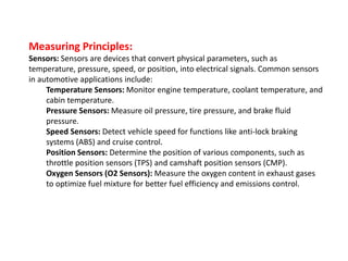
Marathi Call Girls Santacruz WhatsApp +91-9930687706, Best Service
Unit 4 PPT.pptx
1. Unit 4
Chapter 3
AUTOMOTIVE ELECTRONICS AND
SENSORS AND ACTUATORS
BETHLAHEM INSTITUTE OF ENGINEERING ,KARUNGAL,KANYAKUMARI DIST
prepared by R.Monikandakumar AutoAP
3. Measuring Principles:
Sensors: Sensors are devices that convert physical parameters, such as
temperature, pressure, speed, or position, into electrical signals. Common sensors
in automotive applications include:
Temperature Sensors: Monitor engine temperature, coolant temperature, and
cabin temperature.
Pressure Sensors: Measure oil pressure, tire pressure, and brake fluid
pressure.
Speed Sensors: Detect vehicle speed for functions like anti-lock braking
systems (ABS) and cruise control.
Position Sensors: Determine the position of various components, such as
throttle position sensors (TPS) and camshaft position sensors (CMP).
Oxygen Sensors (O2 Sensors): Measure the oxygen content in exhaust gases
to optimize fuel mixture for better fuel efficiency and emissions control.
4. Actuators:
Actuators are devices responsible for converting electrical signals into mechanical
action. Common actuators in vehicles include:
Fuel Injectors: Deliver precise amounts of fuel to the engine cylinders based on
sensor inputs.
Ignition Coils: Generate high-voltage sparks to ignite the air-fuel mixture in
gasoline engines.
Throttle Actuators: Control the opening and closing of the throttle valve based
on driver input and engine load.
Brake Actuators: Control brake pressure in anti-lock braking systems (ABS) and
electronic stability control (ESC) systems.
Transmission Solenoids: Control gear shifting and hydraulic pressure in
automatic transmissions.
Steering Actuators: Assist with power steering and steering wheel position
control.
Control Units:
Electronic control units (ECUs) or control modules process data from
sensors and send control signals to actuators. These units use complex
algorithms to optimize vehicle performance, safety, and fuel efficiency.
5. Automotive Applications of Automotive Actuators:
Engine Management: Actuators and sensors in the engine control module (ECM)
manage various functions, such as fuel injection, ignition timing, and air-fuel mixture
control, to optimize engine performance, fuel efficiency, and emissions.
Transmission Control: Actuators control the shifting of gears in automatic
transmissions, improving driving comfort and fuel efficiency. Transmission control
modules (TCMs) use input from speed sensors and throttle position sensors to optimize
gear shifts.
Brake Systems: In anti-lock braking systems (ABS) and electronic stability control (ESC),
actuators modulate brake pressure to prevent wheel lockup and improve vehicle
stability during braking and cornering.
Airbag Deployment: Actuators trigger airbag deployment in response to crash sensors'
signals, enhancing passenger safety during collisions.
6. Climate Control: Actuators control heating, ventilation, and air conditioning
(HVAC) systems, adjusting airflow, temperature, and distribution to maintain
passenger comfort.
Electric Power Steering (EPS): EPS actuators assist with steering effort and
adjust steering feel based on driving conditions and speed, enhancing driver
control. Road conditions to prevent glare for oncoming drivers.
Throttle Control: Throttle actuators respond to driver input and sensor data
to adjust the throttle valve's position, managing engine power and torque.
Exhaust Gas Recirculation (EGR): Actuators control the EGR valve, which
recirculates exhaust gases into the intake manifold to reduce emissions and
control combustion temperature.
Fuel Delivery: Fuel injectors, driven by actuators, precisely deliver fuel to
each cylinder based on sensor inputs, optimizing combustion efficiency.
Headlamp Leveling: Actuators adjust the angle of headlights based on
vehicle load and
7. Actuators
An actuator is a mechanical or electromechanical device that
converts energy into motion or force.
These devices are used to move or control a system or
mechanism by converting various types of energy into physical motion
5 DIFFERENT TYPES OF ACTUATORS:
Hydraulic actuators: These actuators use pressurized hydraulic fluid to generate mechanical
force. They are used in heavy-duty applications, such as construction equipment, cranes,
and mining machinery.
Pneumatic actuators: These actuators use compressed air or gas to generate force. They
are used in a wide range of applications, including industrial machinery, robotics, and
automation.
Electric linear actuators: These actuators use electrical energy to generate force or motion.
They are used in various applications, including robotics, automation, and HVAC systems.
Piezoelectric actuators: These actuators use the piezoelectric effect to convert electrical
energy into mechanical energy. They are used in precision positioning systems and micro-
manipulation applications.
Thermal actuators: These actuators use thermal energy to generate motion or force. They
are used in applications such as refrigeration and air conditioning systems.
8. Actuators can be found in various applications
Industrial machinery: Actuators are used in various industrial applications, including
conveyor systems, packaging machinery, and production lines.
Robotics: Actuators are used in robotic applications to control the movement and
positioning of robotic arms, grippers, and other components.
Aerospace: Actuators are used in aerospace applications, including flight control
systems, landing gear, and engine control systems.
Automotive: Actuators are used in automotive applications, including power windows,
power locks, and power seats.
Healthcare: Actuators are used in healthcare applications, including prosthetics and
medical equipment
9. Application Device Actuator Type
Automated control of fluid flow in
pipelines and process systems
Control Valve, Flow Meter Linear, Rotary (Hydraulic, Electric)
Adjustment of industrial valves,
positioning of machine components
Ball Valve, Solenoid Valve,
Servo Motor
Rotary (Hydraulic, Electric)
Digging, grading, and excavating in
construction and mining operations
Excavator, Backhoe Linear, Rotary (Hydraulic)
Manufacturing of metal parts,
plastic molding, and forging
operations
Hydraulic Press, CNC
Machine, Forging Hammer
Rotary (Hydraulic, Electric)
Powering machine tools, robots,
and conveyor systems
Electric Motor, Robot Arm,
Conveyor Belt
Linear, Rotary (Electric, Hydraulic)
Positioning of machine components
in automated production systems
Linear Actuator, Servo
Motor, Gripper
Linear, Rotary (Electric, Hydraulic)
Regulating the flow of fuel and air
into internal combustion engines
Throttle Valve, Fuel Injector Rotary (Mechanical, Electric)
Regulating the speed of steam or
gas turbines in power plants
Turbine Governor, Valve Rotary (Electric, Hydraulic, Thermal)
Simple machine control in
mechanical systems, such as door
openers
Mechanical Lever, Electric
Switch
Linear, Rotary (Mechanical, Electric)
Transmission of power in
machines, such as conveyor
systems and gear pumps
Gearbox, Gear Pump,
Hydraulic Motor
Linear, Rotary (Hydraulic,
Mechanical, Electric)
11. CONSTRUCTION
1. Motor:
2. Screw or Rod:
3. Nuts or Carriages:
4. Housing or Enclosure:
5. Feedback System (Optional):
Working Principle of an Electromechanical Actuator:
The working principle of an electromechanical actuator can be summarized in several steps:
Input Electrical Signal: When an electrical signal is applied to the motor, it begins to
rotate. The direction and magnitude of the rotation depend on the polarity and amplitude of
the electrical signal.
Motor Rotation: As the motor rotates, it drives the screw or rod, which, in turn, causes
linear motion. The direction and distance of the linear motion depend on the motor's
rotation and the pitch of the screw or rod threads.
12. Linear Motion: The linear motion of the nut or carriage, which is attached to the
screw or rod, results in the desired mechanical output. This linear motion can be
used for tasks such as moving loads, opening or closing valves, adjusting
positions, or performing other mechanical actions.
Control and Feedback (Optional): In applications that require precise control,
a feedback system may be integrated. The feedback system continuously
monitors the position or velocity of the actuator and provides this information to
a controller. The controller adjusts the electrical signal to the motor to maintain
the desired position or motion.
13. FLUID‐MECHANICAL ACTUATORS
Fluid-mechanical actuators, including both hydraulic and pneumatic
actuators, are devices that use pressurized fluids (liquids or gases) to generate
mechanical motion
They are commonly used in a wide range of industrial applications due to
their ability to provide high force, precise control, and reliable operation.
14. Construction
1. Cylinder:
2. Piston:
3. Rod:
4. Seals and Gaskets:
5. Ports:
6. Control Valves:
7. Fluid Reservoir (Hydraulic Systems):
Working Principle
Fluid Supply: In hydraulic systems, hydraulic fluid is pumped from the reservoir into
the actuator's inlet port. In pneumatic systems, compressed air is supplied to the
actuator through the inlet port.
Actuation: The introduction of pressurized fluid into one of the actuator's chambers
(either the rod side or the cap side) creates a pressure differential across the piston.
This pressure difference generates a force on the piston, causing it to move.
Piston Motion: As the piston moves along the cylinder, it also moves the rod that is
attached to it. This results in linear or rotary motion, depending on the actuator's
design and application.
15. Direction Control: The direction of motion (extension or retraction) is controlled
by adjusting the flow of fluid using control valves. Reversing the flow direction will
change the motion of the piston.
Load Handling: The rod connected to the piston transmits the mechanical motion
to the load or system being controlled. Fluid-mechanical actuators can provide
significant force and are capable of moving heavy loads.
16. 1. Manufacturing: They are used in manufacturing processes for tasks such as clamping,
pressing, and lifting heavy objects.
2. Construction: Hydraulic actuators are employed in construction equipment, such as
excavators, bulldozers, and cranes, for precise control of movement and force.
3. Aerospace: Pneumatic and hydraulic actuators are used in aircraft for functions like
landing gear deployment and flight control surfaces.
4. Automotive: Hydraulic actuators are found in various automotive systems, including
power steering and braking systems.
5. Marine: They are used in ship steering systems and equipment on boats and ships.
6. Material Handling: Fluid-mechanical actuators are used in conveyor systems, forklifts,
and automated material handling equipment.
7. Agriculture: Hydraulic actuators are utilized in agricultural machinery like tractors and
combines.
8. Robotics: They are used in industrial robots for precise and controlled motion.
9. Oil and Gas: Hydraulic actuators are employed in drilling equipment, valves, and
wellhead control systems.
10. Medical Devices: Pneumatic actuators are used in medical devices like surgical robots
and prosthetic limbs.
11. Heavy Machinery: They are used in mining equipment, earthmoving machinery, and
more.
18. Construction of DC Machine
1. Yoke
2. Pole and Pole Core
3. Pole Shoe
4. Field Windings
5. Armature Core
6. Armature Winding
7. Commutator
8. Brushes
Working Principle
Creation of Magnetic Field: When direct current (DC) is applied to the field windings on
the stator, it creates a magnetic field around the pole pieces. This magnetic field is
stationary.
Rotor Rotation: When a voltage is applied to the armature windings on the rotor, a
current flows through them. Due to the magnetic field created by the stator, a force is
exerted on the armature windings, causing the rotor to rotate.
Commutator Action: As the rotor turns, the commutator segments rotate with it. The
brushes maintain contact with the commutator, which reverses the direction of current
flow in the armature windings each time a commutator segment passes under a brush.
19. Mechanical Output: The changing direction of current in the armature
windings creates a rotating magnetic field within the rotor. This interaction
between the stator's stationary magnetic field and the rotor's rotating
magnetic field generates mechanical torque, causing the rotor to continue
rotating. This rotational motion can be used to perform mechanical work,
such as driving a load.
Electrical Output (Generator Mode): In generator mode, when mechanical
energy is applied to the rotor (by external means, not electrical input), the
rotor rotates within the magnetic field. This motion induces an electromotive
force (EMF) in the armature windings, resulting in electrical output voltage
across the brushes.
20. CLASSIFICATION OF DC MACHINE
There are different types of DC machines like series, shunt, short shunt
compound and long shunt compound.
According to the field excitation method, the DC machines are classified as;
• Separately Excited DC Machine
In this type of machine, the field winding is electrically separate from the
armature winding. There is no physical connection between the field winding and
the armature winding.
In separately excited machines, the field winding is supplied from a separate
power source.
• Self-Excited DC Machine
Series Wound DC Machine
Shunt Wound DC Machine
Compound Wound DC Machine
21. Series DC Machine
In this type of DC machine, the field winding is connected in series with the armature winding.
Because of the series connection, the entire load current (armature current) will pass from the field
winding. And this current is high.
So, the series field winding is designed with a smaller number of turns of thick wire to reduce the
resistance.
Shunt Wound DC Machine
In this type of DC machine, the field winding is connected in parallel with the armature winding.
Because of the parallel connection, full voltage is applied to the field winding
Therefore, shunt winding is designed with a large number of turns with high resistance.
The current flow through the field winding is very small. It is just 5% of the rated armature current.
22. Compound Wound DC Machine
In this type of DC machine, two field windings are used. One winding is connected in series
and second winding is connected in parallel with the armature winding.
The compound Wound DC Machine is also classified into two types;
• Short Shunt
• Long Shunt
• Short Shunt
If the field winding is connected in parallel with only the armature winding, the machine is
called a Short shunt compound wound DC machine.
Long Shunt
If the field winding is connected parallel with a combination of series field winding and
armature winding, the machine is called a Long-shunt compound wound DC Machine.
23. Application of DC Machine as a Motor
The DC motors are divided into three types; Series motor, Shunt motor, and
Compound motor.
Series Motor
The series motors are used in the application where high starting torque is
necessary and speed variation is possible.
Example- Vacuum cleaner, Air Compressor, Cranes, Traction system, etc.
Shunt Motor
The shunt motor is used in the application where starting torque is not needed
more and running on the constant speed.
Example- conveyer, Lift, Fans, Lathe machine, Spinning machine, centrifugal
pump, etc.
Compound Motor
The compound motors are used in applications where higher starting with
constant speed is required.
Examples- Rolling mills, Elevators, Conveyer, Presses, etc.
24. Application of DC Machine as Generator
The DC generators are classified as Separately excited DC generator, Shunt-wound,
and Series-Wound generator.
Separately excited DC Generator
This type of DC generator is used for testing in laboratories. Because it has a wide
range of voltage input. It is also used as a supply to DC motor.
Shunt-wound Generator
This type of generator used to charge a battery and provide excitation to the
alternator. This type of generator also used for lighting purposes.
Series-wound Generator
Series-wound generators are used in locomotive for providing field excitation current
as well as for regenerative braking. In a distribution power system, it is used as a
booster
25. Losses in DC Machine
There are three types of losses in the machine. They are Copper losses, Iron losses, and
stray losses.
Copper losses are classified into three armature, shunt field, and series field copper
losses.
Iron losses are classified into two, one is Eddy current, and the other is hysteresis
losses.
Stray losses are classified into two, one is frictional, and the other is windage losses.
26. Single-phase, and three-phase motors
• A single-phase motor is an electrically-powered rotary machine that can turn electric
energy into mechanical energy ,
• Two types of wiring: hot and neutral.,
• Two wires and the current that runs across them is always the same.,
• single-phase motors with a power of up to 10 hp that can work with connections of up to
440V.,
• Easy to repair and maintain, as well as affordable.,
• Motor is used mainly in homes, offices, stores and small non-industrial companies
29. Three conductor lines are used for transmission, but the final use requires 4-wire cables,
which correspond to the 3 phases plus neutral.
A three-phase motor is an electric machine that transforms electric power
into mechanical energy by means of electromagnetic interactions. Some electric motors
are reversible – they can transform mechanical energy into electric power acting as
generators.
They work by using a three-phase power source. They are driven by three alternating
currents of the same frequency, which peak at alternating moments. They can have a
power of up to 300KW and speeds ranging between 900 and 3600 RPM.
THREE-PHASE MOTOR
30. DUTY‐TYPE RATINGS FOR ELECTRICAL MACHINES
1. Continuous Duty (S1)
The motor runs with a constant load for a long enough duration so that it reaches thermal
equilibrium, Example fan
2. Short Time Duty (S2)
Similar to continuous duty, this operation runs with a constant load. Unlike continuous
duty, it is shut off before it reaches thermal equilibrium. number of minutes in the cycle
(S2 30 minutes).
31. 3.Periodic Duty (S3-S8)
These include cycles with and without rest that have starting, electric braking, and/or
changing speeds/loads. Throughout all of these designations, the various operations
of the cycle are repeated over time and the motor is not allowed to reach thermal
equilibrium. eg elevators, punch presses, compactors,adaptable motors
4. Intermittent Periodic Duty (S3)
This sequence of identical cycles each contains a period of constant load and a period
at rest. An example of intermittent periodic duty could be a conveyor that runs at
constant intervals with the same loading.eg plastics machinery, food and beverage
processing,
32. 5. Continuous Operation with Electric Braking
The final example of a motor duty cycle is continuous operation with
electric braking. This cycle includes a sequence of starting, constant load,
and electric braking