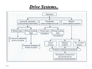
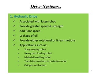
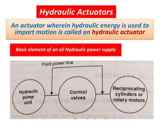
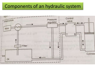
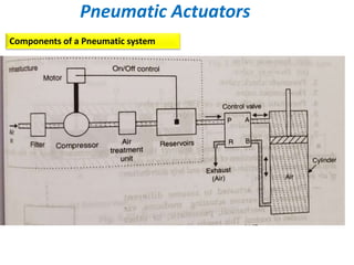
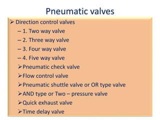
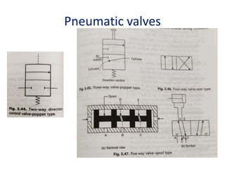
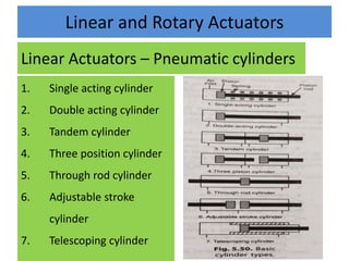
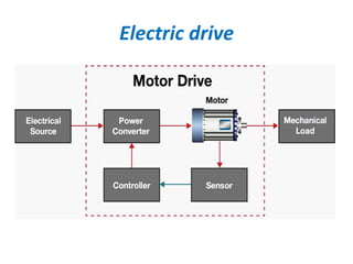
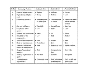
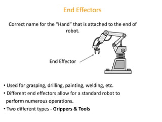
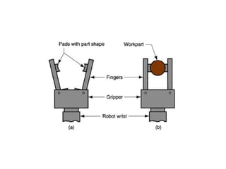
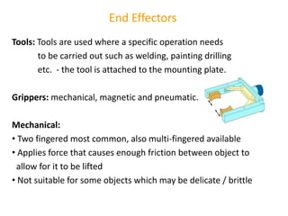
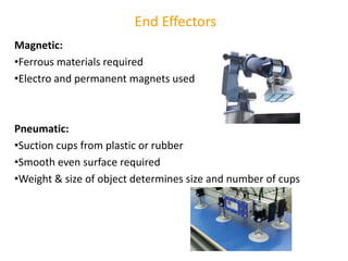
The document discusses various robot drive systems and end effectors, focusing on four main types: hydraulic, pneumatic, electric, and mechanical. It details the functionalities, advantages, and application areas of each drive system, as well as specific components like actuators, motors, and valves that enable robot movement. Additionally, it elaborates on end effectors, describing different types such as grippers and tools, and their mechanisms, including mechanical, magnetic, and pneumatic options.
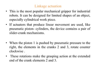
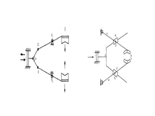


![[Deck] What's New in Spark-Iceberg Integration via DSV2.pptx](https://cdn.slidesharecdn.com/ss_thumbnails/deckwhatsnewinspark-icebergintegrationviadsv2-260210005337-25955b12-thumbnail.jpg?width=640&height=640&fit=bounds)


