Downloaded 88 times


![(b). Based on the cylinder action
• (1) single acting cylinder
Single acting cylinder has one working port. Forward motion of
the piston is obtained by supplying
compressed air to working port. Return motion of piston is
obtained by spring placed on the rod side of the cylinder
Single acting cylinders are used where force is required to be
exerted only in one direction. Such as
clamping, feeding, sorting, locking, ejecting, braking etc.,
Single acting cylinder is usually available in short stroke lengths
[maximum length up to 80 mm] due
to the natural length of the spring. Single Acting Cylinder exert
force only in one direction. Single
acting cylinders require only about half the air volume
consumed by a double acting cylinder for one
operating cycle.](https://image.slidesharecdn.com/doc-20190625-wa0004-190625102218/75/Presentation-on-pneumatic-actuator-8-2048.jpg)


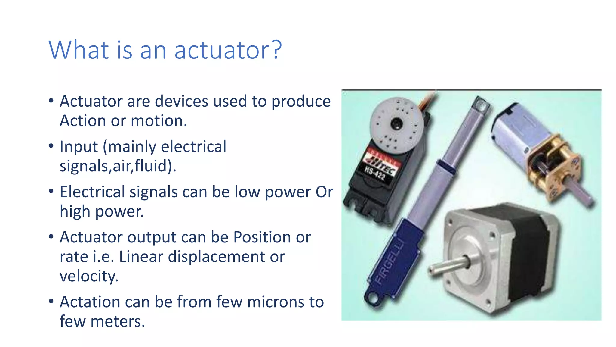
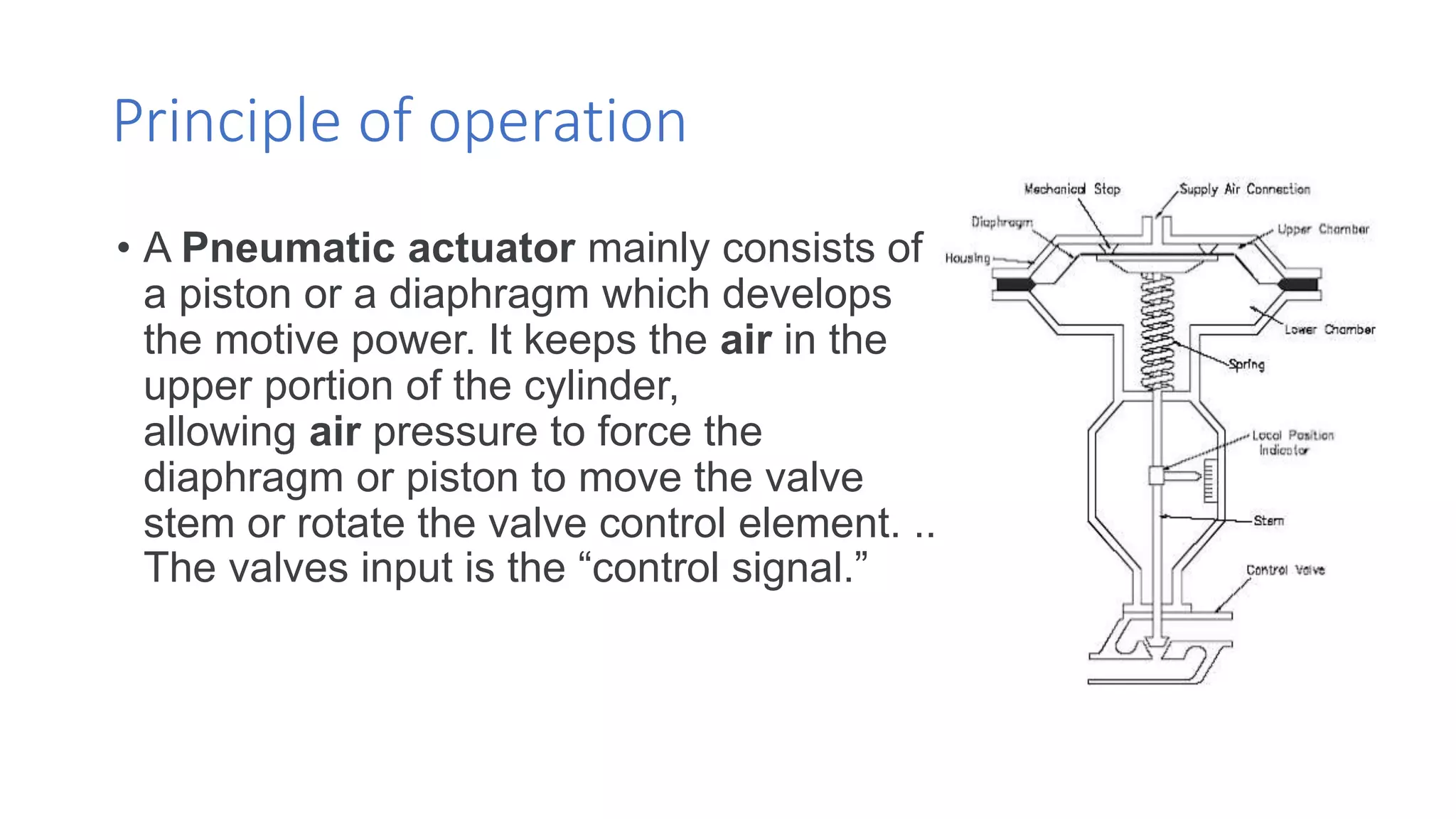
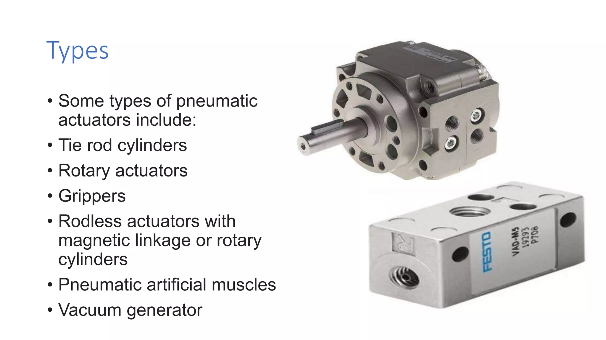
The document provides an overview of pneumatic actuators, which convert compressed air energy into linear or rotary motion. It details the principle of operation, types of pneumatic actuators, and classifications based on applications, actions, and designs. Specific types discussed include single acting and double acting cylinders, along with their operational mechanisms and applications.