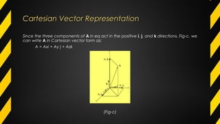
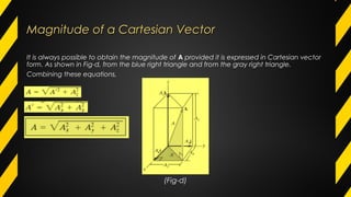
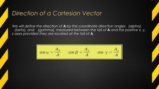
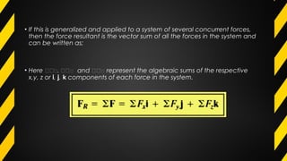
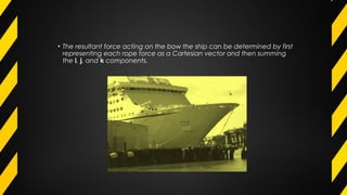
Force VectorsForce VectorsForce VectorsForce Vectors
ObjectivesObjectives
• To show how to add forces and resolve them into components using the
Parallelogram Law.
• To express force and position in Cartesian vector form and explain how to
determine the vector’s magnitude and direction.
• To introduce the dot product in order to determine the angle between two
vectors or the projection of one vector onto another.
OutlineOutline
• Scalars and Vectors
• Vector Operations
• Vector Addition of Forces
• Addition of a System of Coplanar Forces
• Cartesian Vectors
Scalars and VectorsScalars and Vectors
All physical quantities in engg: mechanics are measured using either
scalars or vectors.
Scalar:
A scalar is any positive or negative physical quantity that can be
completely specified by its magnitude.
Eg: Length, Mass, and Time.
Scalars and VectorsScalars and Vectors
Vector:
• A quantity that has both magnitude and direction for its complete
description
• Eg: Position, force and moment
• Represent by a letter with an arrow over it such as A or A
• Magnitude is designated as A or simply A
• vector is presented as A and its magnitude (positive quantity) as A
Vector
• Represented graphically as an arrow
• Length of arrow = Magnitude of Vector
• Angle between the reference axis and arrow’s line of action = Direction of
Vector
• Arrowhead = Sense of Vector
• Example: Magnitude of Vector = 4 units
• Direction of Vector = 20° measured counterclockwise from the horizontal
axis
• Sense of Vector = Upward and to the right
• The point O is called tail of the vector and the point P is called
the tip or head
Vector OperationsVector Operations
Vector Addition
•Addition of two vectors A and B gives a resultant vector R by the parallelogram law
•Result R can be found by triangle construction.
•Ex: R = A + B, using the following procedure:
•First join the tails of the components at a point so that it makes them concurrent, Fig. b
• From the head of B, draw a line parallel to A. Draw another line from the head of A that is
parallel to B. These two lines intersect at point P to form the adjacent sides of a
parallelogram.
• The diagonal of this parallelogram that extends to P forms R, which then represents the
resultant vector R = A + B. fig-c
• We can also add B to A, Fig. a, using the triangle rule, which is a special case of the
parallelogram law, where by vector B is added to vector A in a “head-to-tail” rule i.e.,
by connecting the head of A to the tail of B, Fig.b. The resultant R extends from the tail
of A to the head of B. In a similar manner, R can also be obtained by adding A to B,
Fig.c.
Vector Subtraction
•Special case of addition
•Ex: R’ = A – B = A + ( - B )
•Rules of Vector Addition Applies
Vector Addition of ForcesVector Addition of Forces
• Force is a vector quantity it adds according to the parallelogram law.
• Two common problems in statics involve either finding the resultant force, knowing its
components, or resolving a known force into two components.
• We will describe how each of these problems is solved using the parallelogram law.
Finding a Resultant Force.
•The two component forces F1 and F2
•acting on the pin in Fig.a can be added together to form the resultant force
FR = F1 + F2, as shown in Fig.b .
• From this construction, or using the triangle rule, Fig. c, we can apply the law
of cosines or the law of sines to the triangle in order to obtain the magnitude
of the resultant force and its direction
Procedure for AnalysisProcedure for Analysis
• Problems that involve the addition of two forces can be solved as follows:
• Parallelogram Law.
• Two “component” forces F1 and F2 in Fig. a add according to the parallelogram
law, yielding a resultant force FR that forms the diagonal of the parallelogram.
• Label all the forces magnitudes and the angles on the sketch and identify the two
unknowns as the magnitude and direction of FR, or the magnitudes of its
components.
Trigonometry.
• Redraw a half portion of the parallelogram to illustrate the triangular head-to-
tail addition of the components.
• From this triangle, the magnitude of the resultant force can be determined
using the law of cosines, and its direction is determined from the law of sines.
The magnitudes of two force components are determined from the law of
sines. The formulas are given in Fig. c.
• Example 2.1
• The screw eye is subjected to two forces F1 and F2. Determine the magnitude and direction
of the resultant force.
• Solution
• By Parallelogram Law
• To Find : magnitude of FR and angle θ
Solution
•Law of Cosines
Solution
Law of Sines
• Direction Φ of FR measured from the horizontal
Example 2Example 2
• Determine the magnitude of the component force F in Fig.a and the magnitude of the
resultant force FR if FR is directed along the positive y axis.
SOLUTION
•The parallelogram law of addition is shown in Fig. , and the triangle rule is
shown in Fig.c.The magnitudes of FR and F are the two unknowns. They can be
determined by applying the law of sines.
(b) (c)
• Finding the Components of a Force. Sometimes it is necessary to resolve a
force into two components in order to study its pulling or pushing effect in
two specific directions.
• For example, in Fig. 2a, F is to be resolved into two components along the
two members, defined by the u and axes. In order to determine the
magnitude of each component, a parallelogram is constructed first, by
drawing lines starting from the tip
of F, one line parallel to u, and the other line parallel to . These lines then intersect
with the and u axes, forming a parallelogram. The force components Fu and F are
then established by simply joining the tail of F to the intersection points on the u
and axes, Fig. 2–b. This parallelogram can then be reduced to a triangle, which
represents the triangle rule, Fig. 2–c. From this, the law of sine can then be applied
to determine the unknown magnitudes of the components.
Addition of a system of coplanar forcesAddition of a system of coplanar forces
When a force in resolved into two components along the x and y axes
the components are then called rectangular components.
we can represent these components in one of two ways, using either Scalar
notation or Cartesian vector notation. The rectangular components of force F
shown in Fig 2.23 are found
using the parallelogram law, so that
Scalar Notation: The rectangular components of force F shown in Fig-a are found using
the parallelogram law, so that F = Fx + Fy
Because these components form a right triangle, their magnitudes can be
determined from
𝐅 = 𝐅𝐅 + 𝐅𝐅
𝐅𝐅 = 𝐅 𝐅𝐅𝐅 𝐅
𝐅𝐅 = 𝐅 sin 𝐅
Cartesian VectorsCartesian Vectors
• The operations of vector algebra, when applied to solving problems in three
dimensions, are simplified if the vectors are first represented in Cartesian
vector form.
Right-Handed Coordinate System
• The right handed coordinate system is used to develop the theory of vector
algebra as;
• A rectangular coordinate system is said to be right-handed if the
• thumb of right hand points in the direction of the positive z axis’
• the right-hand fingers are curled about x axis and
• the arm directed towards the positive y axis.
Rectangular Components of a Vector
•A vector 𝐀 may have three rectangular components along the x, y, z
coordinate axes and is represented by the vector sum of its three rectangular
components. (Fig-a).
𝐀 = 𝐀𝐀 + 𝐀𝐀 + 𝐀𝐀
(Fig-a)
Cartesian Unit Vectors.
•In three dimensions, the set of Cartesian unit 𝐀 , 𝐀 , 𝐀 is used to
designate the directions of the x, y, z axes, respectively. The positive
Cartesian unit vectors are shown in Fig-b.
(Fig-b)
Cartesian Vector RepresentationCartesian Vector Representation
Since the three components of A in eq act in the positive i, j, and k directions, Fig-c, we
can write A in Cartesian vector form as;
A = Axi + Ay j + Azk
(Fig-c)
Magnitude of a Cartesian VectorMagnitude of a Cartesian Vector
It is always possible to obtain the magnitude of A provided it is expressed in Cartesian vector
form. As shown in Fig-d, from the blue right triangle and from the gray right triangle.
Combining these equations,
(Fig-d)
Direction of a Cartesian VectorDirection of a Cartesian Vector
We will define the direction of A by the coordinate direction angles ∝(alpha),
𝐀(beta), and 𝐀(gamma), measured between the tail of A and the positive x, y,
z axes provided they are located at the tail of A,
(Fig-e)
• An easy way of obtaining these direction cosines is to form a unit vector uA in the
direction of A, Fig-e. If A is expressed in Cartesian vector form, A = Axi + Ay j + Azk,
then uA will have a magnitude of one and be dimensionless provided A is divided by
its magnitude.
• where. By comparison with, it is seen that the i, j, k components of uA represent the
direction cosines of A, i.e.,
• uA = cos ∝i + cos 𝐀j + cos 𝐀k
• Since the magnitude of a vector is equal to the positive square root of the sum of the
squares of the magnitudes of its components, and uA has a magnitude of one, then
from the above equation an important relation between the direction cosines can be
formulated as
cos2
+cos∝ 2
𝐀 +cos2
𝐀 = 1
• Here we can see that if only two of the coordinate angles are known, the third
angle can be found using this equation.
• Finally, if the magnitude and coordinate direction angles of A are known, then A
may be expressed in Cartesian vector form as
Addition of Cartesian VectorsAddition of Cartesian Vectors
• The addition (or subtraction) of two or more vectors are greatly simplified if the
vectors are expressed in terms of their Cartesian components.
• For example, if A = Axi + Ay j + Azk and B = Bxi + Byj + Bzk, Fig-f, then the resultant
vector,R, has components which are the scalar sums of the i, j, k components of A
and B, i.e.,
• R = A + B = (Ax + Bx)i + (Ay + By)j + (Az + Bz)k
• If this is generalized and applied to a system of several concurrent forces,
then the force resultant is the vector sum of all the forces in the system and
can be written as;
• Here 𝛴𝛴 𝛴, 𝛴𝛴 𝛴 and 𝛴𝛴 𝛴 represent the algebraic sums of the respective
x,y, z or i, j, k components of each force in the system.
• The resultant force acting on the bow the ship can be determined by first
representing each rope force as a Cartesian vector and then summing
the i, j, and k components.
ConclusionConclusion
• Cartesian vector analysis is often used to solve problems in three
dimensions.
• The positive directions of the x, y, z axes are defined by the Cartesian
unit vectors i, j, k, respectively.
• The magnitude of a Cartesian vector is
• The direction of a Cartesian vector is specified using coordinate direction angles � �∝
which the tail of the vector makes with the positive x, y, z axes, respectively. The
components of the unit vector uA = A/A represent the direction cosines of � � .∝
• Only two of the angles , �, � have to be specified. The third angle is determined from∝
the relationship cos2
+cos∝ 2
� +cos2
� = 1
• To find the resultant of a concurrent force system, express each force as a Cartesian
vector and add the i, j, k components of all the forces in the system.
MechanicsMechanics
Mechanics is divided into two areas;
• Satatics &
• Dynamics
Satatics deals with the equilibrium of bodies , those that are either at
rest or
move with a constant velocity
OR
Statics is branch of mechanics, which deals with the forces and their
effects, while acting upon the bodies at rest.
MechanicsMechanics
Dynamics
• The part of mechanics which deals with the analysis of bodies in
motion.
• Dynamics is concerned with the accelerated motion of bodies
• Dynamics is branch of mechanics, which deals with the forces and
their effects, while acting upon the bodies in motion.
• The study of the causes of motion is called "dynamics".
DynamicsDynamics
We conclude that;
• Statics concerns with forces when no change in momentum occurs.
• Dynamics is concerned with forces and matter when a change in
momentum does occur.
• Dynamics is sub divided into ;
-Kinematics &
-Kinetics
KinematicsKinematics
• It deals with the motion of bodies without any reference to the forces acting on it
• Kinematics is a study of motion without regard to the forces present. It is simply a
mathematical way to describe motion.
• Kinematics can be used to find the possible range of motion for a
given mechanism.
• The movement of a crane and the oscillations of a piston in an engine are both
simple example of kinematic systems.
KinematicsKinematics
• Kinematics is not to be confused with another branch of mechanics
into kinetics (the study of the relation between external forces and motion)
and statics (the study of the relations in a system at equilibrium). 
• The simplest application of kinematics is for particle motion, translational or
rotational.
• Kinematics is simply the study of motion
KineticsKinetics
• Kinetics deals with motion of bodies due the application of forces.
• kinetics is a term for the branch of mechanics that is concerned with the
relationship between the motion of bodies and its causes, namely forces and
torques.
• The relation between the external forces and their kinematic variables is
popularly known as kinetics.
Kinematics of particlesKinematics of particles
• Rectilinear motion
- Position, velocity, acceleration
• Curvilinear motion
-Position, velocity, acceleration
• Projectile motion
Kinetics of particlesKinetics of particles
• Force & Acceleration
-Newton’s 2nd
law of motion
-Equations of motion
• Work & Energy
-Principle of work & energy
-Power & efficiency
• Impulse & Momentum
-Principle of Impulse & momentum.
Kinematics of particlesKinematics of particles
• Position: Distance of a body from a certain reference point is called position.
• Rectilinear motion: A particle moving along a straight line is said to be in
rectilinear motion.
• Displacement is a vector describing the difference in position between two
points, i.e. it is the change in position the particle undergoes during the time
interval.
Kinematics of particlesKinematics of particles
Velocity and speed
• Speed Distance covered by body per unit time is called speed. It is scalar quantity.
Speed=Distance/Time = s/t
• Velocity is the measure of the rate of change of displacement (change in position with
respect to time); that is, how the distance of a point changes with each instant of time, It is
vector quantity
Kinematics of particlesKinematics of particles
• Velocity= Displacement / Time
v = Δs / Δt
where Δs is the change in displacement and Δt is the interval of time over
Acceleration The rate of change of velocity is called acceleration. It is a
vector quantity describing the rate of change with time of velocity.
a = Δv / Δt
Kinematics of particlesKinematics of particles
acceleration = change in velocity / time
a = Δv / Δt
where Δv is the change in velocity and Δt is the interval of time over
which velocity changes.
v= ds/dt
a=dv/dt
v=ds/dv/a
ads=vdv
Skillcruise.com

Force vectors

  • 1.
    Force VectorsForce VectorsForceVectorsForce Vectors
  • 2.
    ObjectivesObjectives • To showhow to add forces and resolve them into components using the Parallelogram Law. • To express force and position in Cartesian vector form and explain how to determine the vector’s magnitude and direction. • To introduce the dot product in order to determine the angle between two vectors or the projection of one vector onto another.
  • 3.
    OutlineOutline • Scalars andVectors • Vector Operations • Vector Addition of Forces • Addition of a System of Coplanar Forces • Cartesian Vectors
  • 4.
    Scalars and VectorsScalarsand Vectors All physical quantities in engg: mechanics are measured using either scalars or vectors. Scalar: A scalar is any positive or negative physical quantity that can be completely specified by its magnitude. Eg: Length, Mass, and Time.
  • 5.
    Scalars and VectorsScalarsand Vectors Vector: • A quantity that has both magnitude and direction for its complete description • Eg: Position, force and moment • Represent by a letter with an arrow over it such as A or A • Magnitude is designated as A or simply A • vector is presented as A and its magnitude (positive quantity) as A
  • 6.
    Vector • Represented graphicallyas an arrow • Length of arrow = Magnitude of Vector • Angle between the reference axis and arrow’s line of action = Direction of Vector • Arrowhead = Sense of Vector
  • 7.
    • Example: Magnitudeof Vector = 4 units • Direction of Vector = 20° measured counterclockwise from the horizontal axis • Sense of Vector = Upward and to the right • The point O is called tail of the vector and the point P is called the tip or head
  • 8.
    Vector OperationsVector Operations VectorAddition •Addition of two vectors A and B gives a resultant vector R by the parallelogram law •Result R can be found by triangle construction. •Ex: R = A + B, using the following procedure: •First join the tails of the components at a point so that it makes them concurrent, Fig. b
  • 10.
    • From thehead of B, draw a line parallel to A. Draw another line from the head of A that is parallel to B. These two lines intersect at point P to form the adjacent sides of a parallelogram. • The diagonal of this parallelogram that extends to P forms R, which then represents the resultant vector R = A + B. fig-c
  • 11.
    • We canalso add B to A, Fig. a, using the triangle rule, which is a special case of the parallelogram law, where by vector B is added to vector A in a “head-to-tail” rule i.e., by connecting the head of A to the tail of B, Fig.b. The resultant R extends from the tail of A to the head of B. In a similar manner, R can also be obtained by adding A to B, Fig.c.
  • 12.
    Vector Subtraction •Special caseof addition •Ex: R’ = A – B = A + ( - B ) •Rules of Vector Addition Applies
  • 13.
    Vector Addition ofForcesVector Addition of Forces • Force is a vector quantity it adds according to the parallelogram law. • Two common problems in statics involve either finding the resultant force, knowing its components, or resolving a known force into two components. • We will describe how each of these problems is solved using the parallelogram law.
  • 14.
    Finding a ResultantForce. •The two component forces F1 and F2 •acting on the pin in Fig.a can be added together to form the resultant force FR = F1 + F2, as shown in Fig.b .
  • 15.
    • From thisconstruction, or using the triangle rule, Fig. c, we can apply the law of cosines or the law of sines to the triangle in order to obtain the magnitude of the resultant force and its direction
  • 16.
    Procedure for AnalysisProcedurefor Analysis • Problems that involve the addition of two forces can be solved as follows: • Parallelogram Law. • Two “component” forces F1 and F2 in Fig. a add according to the parallelogram law, yielding a resultant force FR that forms the diagonal of the parallelogram. • Label all the forces magnitudes and the angles on the sketch and identify the two unknowns as the magnitude and direction of FR, or the magnitudes of its components.
  • 17.
    Trigonometry. • Redraw ahalf portion of the parallelogram to illustrate the triangular head-to- tail addition of the components. • From this triangle, the magnitude of the resultant force can be determined using the law of cosines, and its direction is determined from the law of sines. The magnitudes of two force components are determined from the law of sines. The formulas are given in Fig. c.
  • 19.
    • Example 2.1 •The screw eye is subjected to two forces F1 and F2. Determine the magnitude and direction of the resultant force.
  • 20.
    • Solution • ByParallelogram Law • To Find : magnitude of FR and angle θ
  • 21.
  • 22.
  • 23.
    • Direction Φof FR measured from the horizontal
  • 24.
    Example 2Example 2 •Determine the magnitude of the component force F in Fig.a and the magnitude of the resultant force FR if FR is directed along the positive y axis.
  • 25.
    SOLUTION •The parallelogram lawof addition is shown in Fig. , and the triangle rule is shown in Fig.c.The magnitudes of FR and F are the two unknowns. They can be determined by applying the law of sines. (b) (c)
  • 27.
    • Finding theComponents of a Force. Sometimes it is necessary to resolve a force into two components in order to study its pulling or pushing effect in two specific directions. • For example, in Fig. 2a, F is to be resolved into two components along the two members, defined by the u and axes. In order to determine the magnitude of each component, a parallelogram is constructed first, by drawing lines starting from the tip
  • 28.
    of F, oneline parallel to u, and the other line parallel to . These lines then intersect with the and u axes, forming a parallelogram. The force components Fu and F are then established by simply joining the tail of F to the intersection points on the u and axes, Fig. 2–b. This parallelogram can then be reduced to a triangle, which represents the triangle rule, Fig. 2–c. From this, the law of sine can then be applied to determine the unknown magnitudes of the components.
  • 30.
    Addition of asystem of coplanar forcesAddition of a system of coplanar forces When a force in resolved into two components along the x and y axes the components are then called rectangular components. we can represent these components in one of two ways, using either Scalar notation or Cartesian vector notation. The rectangular components of force F shown in Fig 2.23 are found using the parallelogram law, so that
  • 31.
    Scalar Notation: Therectangular components of force F shown in Fig-a are found using the parallelogram law, so that F = Fx + Fy Because these components form a right triangle, their magnitudes can be determined from 𝐅 = 𝐅𝐅 + 𝐅𝐅 𝐅𝐅 = 𝐅 𝐅𝐅𝐅 𝐅 𝐅𝐅 = 𝐅 sin 𝐅
  • 32.
    Cartesian VectorsCartesian Vectors •The operations of vector algebra, when applied to solving problems in three dimensions, are simplified if the vectors are first represented in Cartesian vector form. Right-Handed Coordinate System • The right handed coordinate system is used to develop the theory of vector algebra as;
  • 33.
    • A rectangularcoordinate system is said to be right-handed if the • thumb of right hand points in the direction of the positive z axis’ • the right-hand fingers are curled about x axis and • the arm directed towards the positive y axis.
  • 34.
    Rectangular Components ofa Vector •A vector 𝐀 may have three rectangular components along the x, y, z coordinate axes and is represented by the vector sum of its three rectangular components. (Fig-a). 𝐀 = 𝐀𝐀 + 𝐀𝐀 + 𝐀𝐀 (Fig-a)
  • 35.
    Cartesian Unit Vectors. •Inthree dimensions, the set of Cartesian unit 𝐀 , 𝐀 , 𝐀 is used to designate the directions of the x, y, z axes, respectively. The positive Cartesian unit vectors are shown in Fig-b. (Fig-b)
  • 36.
    Cartesian Vector RepresentationCartesianVector Representation Since the three components of A in eq act in the positive i, j, and k directions, Fig-c, we can write A in Cartesian vector form as; A = Axi + Ay j + Azk (Fig-c)
  • 37.
    Magnitude of aCartesian VectorMagnitude of a Cartesian Vector It is always possible to obtain the magnitude of A provided it is expressed in Cartesian vector form. As shown in Fig-d, from the blue right triangle and from the gray right triangle. Combining these equations, (Fig-d)
  • 38.
    Direction of aCartesian VectorDirection of a Cartesian Vector We will define the direction of A by the coordinate direction angles ∝(alpha), 𝐀(beta), and 𝐀(gamma), measured between the tail of A and the positive x, y, z axes provided they are located at the tail of A,
  • 39.
  • 41.
    • An easyway of obtaining these direction cosines is to form a unit vector uA in the direction of A, Fig-e. If A is expressed in Cartesian vector form, A = Axi + Ay j + Azk, then uA will have a magnitude of one and be dimensionless provided A is divided by its magnitude.
  • 42.
    • where. Bycomparison with, it is seen that the i, j, k components of uA represent the direction cosines of A, i.e., • uA = cos ∝i + cos 𝐀j + cos 𝐀k
  • 43.
    • Since themagnitude of a vector is equal to the positive square root of the sum of the squares of the magnitudes of its components, and uA has a magnitude of one, then from the above equation an important relation between the direction cosines can be formulated as cos2 +cos∝ 2 𝐀 +cos2 𝐀 = 1
  • 44.
    • Here wecan see that if only two of the coordinate angles are known, the third angle can be found using this equation. • Finally, if the magnitude and coordinate direction angles of A are known, then A may be expressed in Cartesian vector form as
  • 45.
    Addition of CartesianVectorsAddition of Cartesian Vectors • The addition (or subtraction) of two or more vectors are greatly simplified if the vectors are expressed in terms of their Cartesian components. • For example, if A = Axi + Ay j + Azk and B = Bxi + Byj + Bzk, Fig-f, then the resultant vector,R, has components which are the scalar sums of the i, j, k components of A and B, i.e.,
  • 46.
    • R =A + B = (Ax + Bx)i + (Ay + By)j + (Az + Bz)k
  • 47.
    • If thisis generalized and applied to a system of several concurrent forces, then the force resultant is the vector sum of all the forces in the system and can be written as; • Here 𝛴𝛴 𝛴, 𝛴𝛴 𝛴 and 𝛴𝛴 𝛴 represent the algebraic sums of the respective x,y, z or i, j, k components of each force in the system.
  • 48.
    • The resultantforce acting on the bow the ship can be determined by first representing each rope force as a Cartesian vector and then summing the i, j, and k components.
  • 49.
    ConclusionConclusion • Cartesian vectoranalysis is often used to solve problems in three dimensions. • The positive directions of the x, y, z axes are defined by the Cartesian unit vectors i, j, k, respectively. • The magnitude of a Cartesian vector is
  • 50.
    • The directionof a Cartesian vector is specified using coordinate direction angles � �∝ which the tail of the vector makes with the positive x, y, z axes, respectively. The components of the unit vector uA = A/A represent the direction cosines of � � .∝ • Only two of the angles , �, � have to be specified. The third angle is determined from∝ the relationship cos2 +cos∝ 2 � +cos2 � = 1
  • 51.
    • To findthe resultant of a concurrent force system, express each force as a Cartesian vector and add the i, j, k components of all the forces in the system.
  • 52.
    MechanicsMechanics Mechanics is dividedinto two areas; • Satatics & • Dynamics Satatics deals with the equilibrium of bodies , those that are either at rest or move with a constant velocity OR Statics is branch of mechanics, which deals with the forces and their effects, while acting upon the bodies at rest.
  • 53.
    MechanicsMechanics Dynamics • The partof mechanics which deals with the analysis of bodies in motion. • Dynamics is concerned with the accelerated motion of bodies • Dynamics is branch of mechanics, which deals with the forces and their effects, while acting upon the bodies in motion. • The study of the causes of motion is called "dynamics".
  • 54.
    DynamicsDynamics We conclude that; •Statics concerns with forces when no change in momentum occurs. • Dynamics is concerned with forces and matter when a change in momentum does occur. • Dynamics is sub divided into ; -Kinematics & -Kinetics
  • 55.
    KinematicsKinematics • It dealswith the motion of bodies without any reference to the forces acting on it • Kinematics is a study of motion without regard to the forces present. It is simply a mathematical way to describe motion. • Kinematics can be used to find the possible range of motion for a given mechanism. • The movement of a crane and the oscillations of a piston in an engine are both simple example of kinematic systems.
  • 56.
    KinematicsKinematics • Kinematics is notto be confused with another branch of mechanics into kinetics (the study of the relation between external forces and motion) and statics (the study of the relations in a system at equilibrium).  • The simplest application of kinematics is for particle motion, translational or rotational. • Kinematics is simply the study of motion
  • 57.
    KineticsKinetics • Kinetics dealswith motion of bodies due the application of forces. • kinetics is a term for the branch of mechanics that is concerned with the relationship between the motion of bodies and its causes, namely forces and torques. • The relation between the external forces and their kinematic variables is popularly known as kinetics.
  • 58.
    Kinematics of particlesKinematicsof particles • Rectilinear motion - Position, velocity, acceleration • Curvilinear motion -Position, velocity, acceleration • Projectile motion
  • 59.
    Kinetics of particlesKineticsof particles • Force & Acceleration -Newton’s 2nd law of motion -Equations of motion • Work & Energy -Principle of work & energy -Power & efficiency • Impulse & Momentum -Principle of Impulse & momentum.
  • 60.
    Kinematics of particlesKinematicsof particles • Position: Distance of a body from a certain reference point is called position. • Rectilinear motion: A particle moving along a straight line is said to be in rectilinear motion. • Displacement is a vector describing the difference in position between two points, i.e. it is the change in position the particle undergoes during the time interval.
  • 61.
    Kinematics of particlesKinematicsof particles Velocity and speed • Speed Distance covered by body per unit time is called speed. It is scalar quantity. Speed=Distance/Time = s/t • Velocity is the measure of the rate of change of displacement (change in position with respect to time); that is, how the distance of a point changes with each instant of time, It is vector quantity
  • 62.
    Kinematics of particlesKinematicsof particles • Velocity= Displacement / Time v = Δs / Δt where Δs is the change in displacement and Δt is the interval of time over Acceleration The rate of change of velocity is called acceleration. It is a vector quantity describing the rate of change with time of velocity. a = Δv / Δt
  • 63.
    Kinematics of particlesKinematicsof particles acceleration = change in velocity / time a = Δv / Δt where Δv is the change in velocity and Δt is the interval of time over which velocity changes. v= ds/dt a=dv/dt v=ds/dv/a ads=vdv
  • 64.