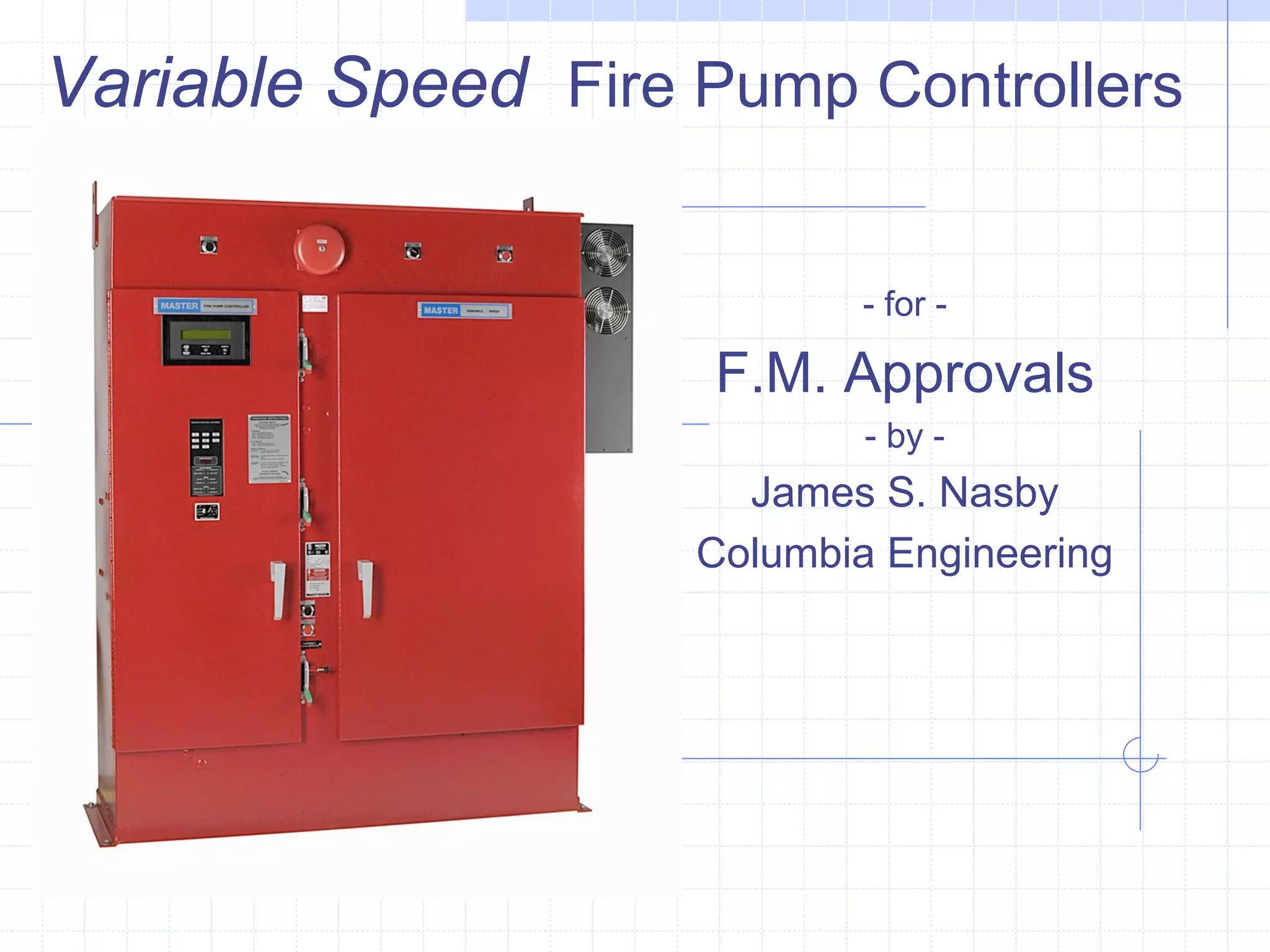
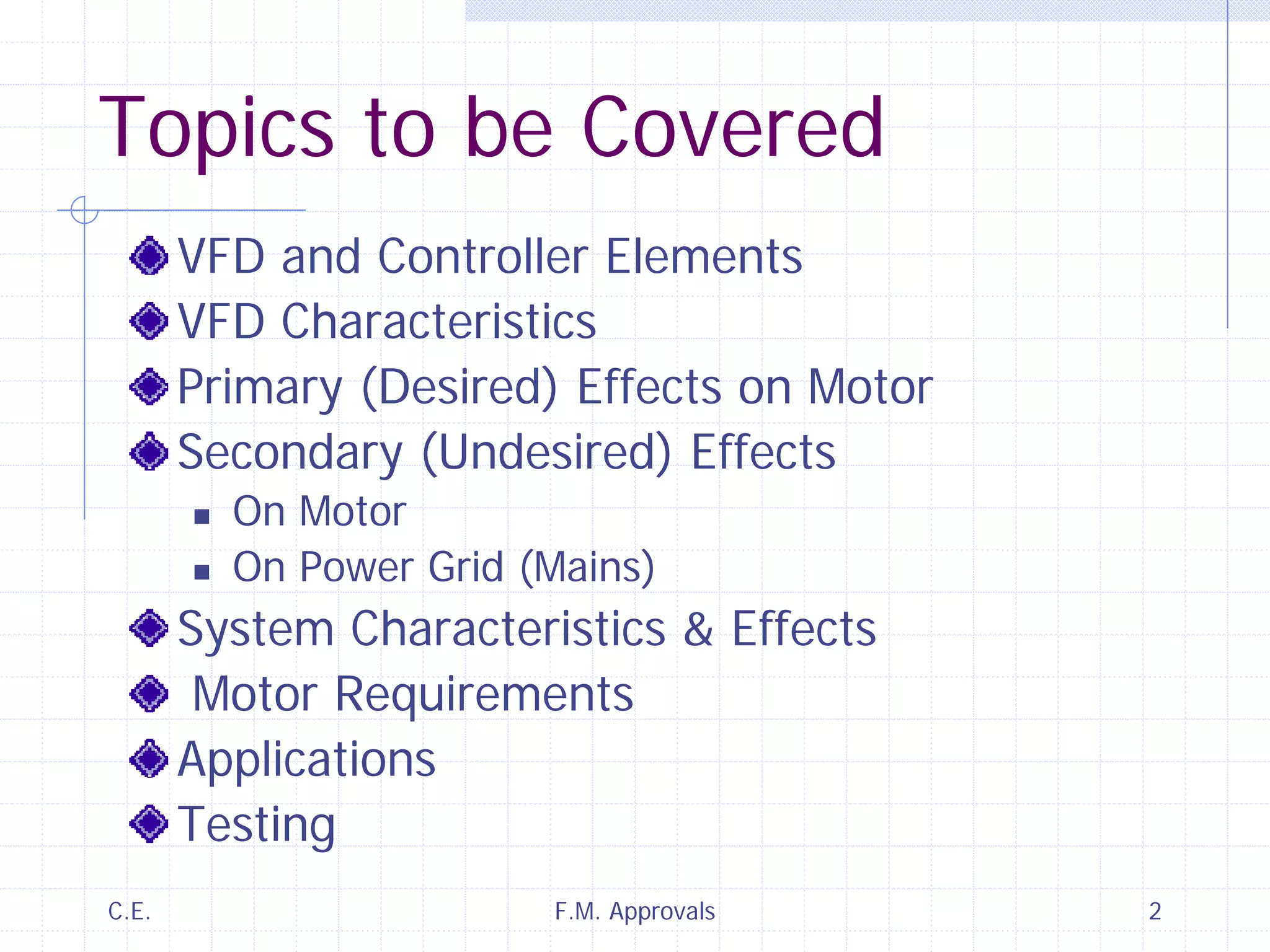
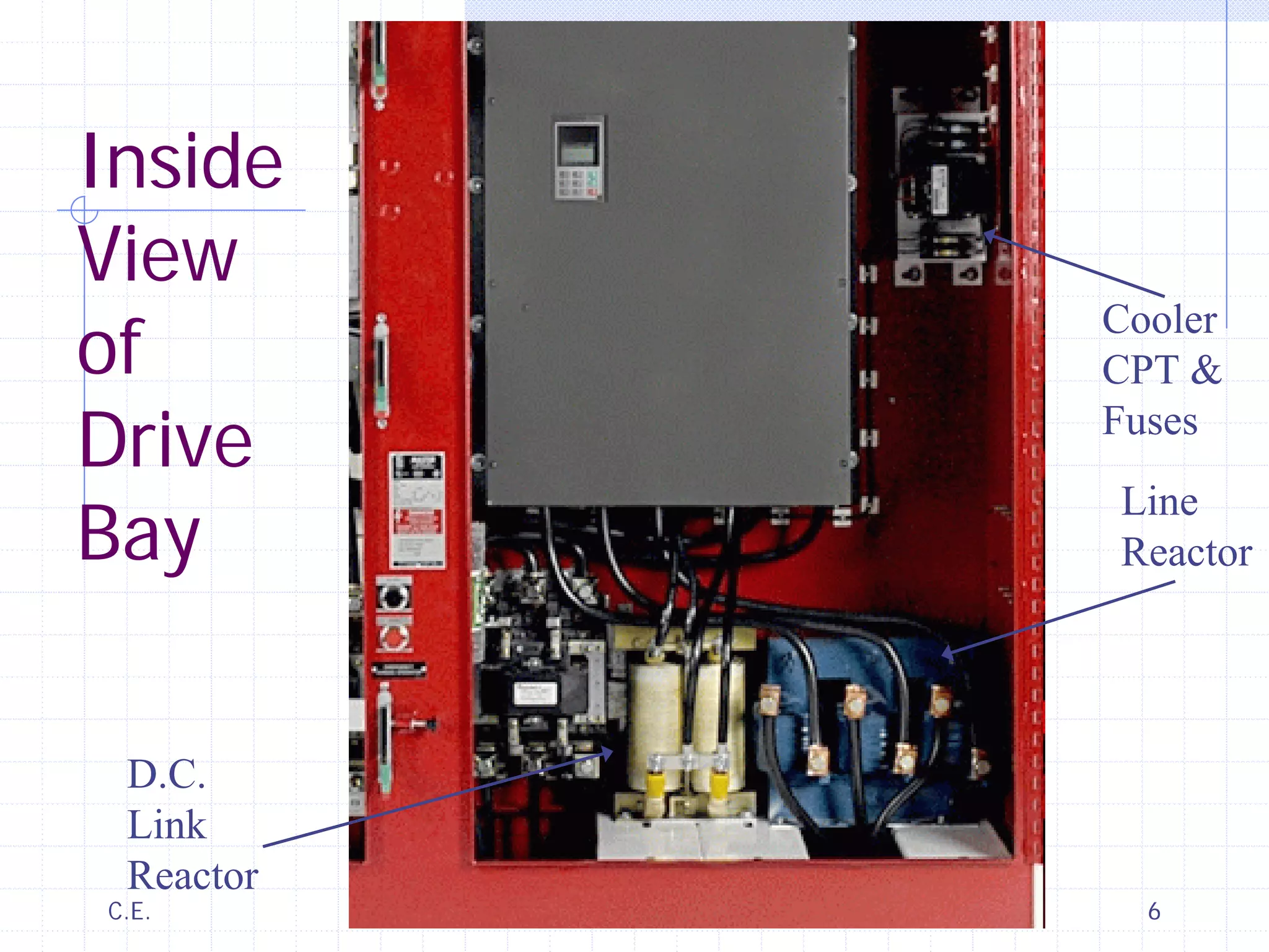
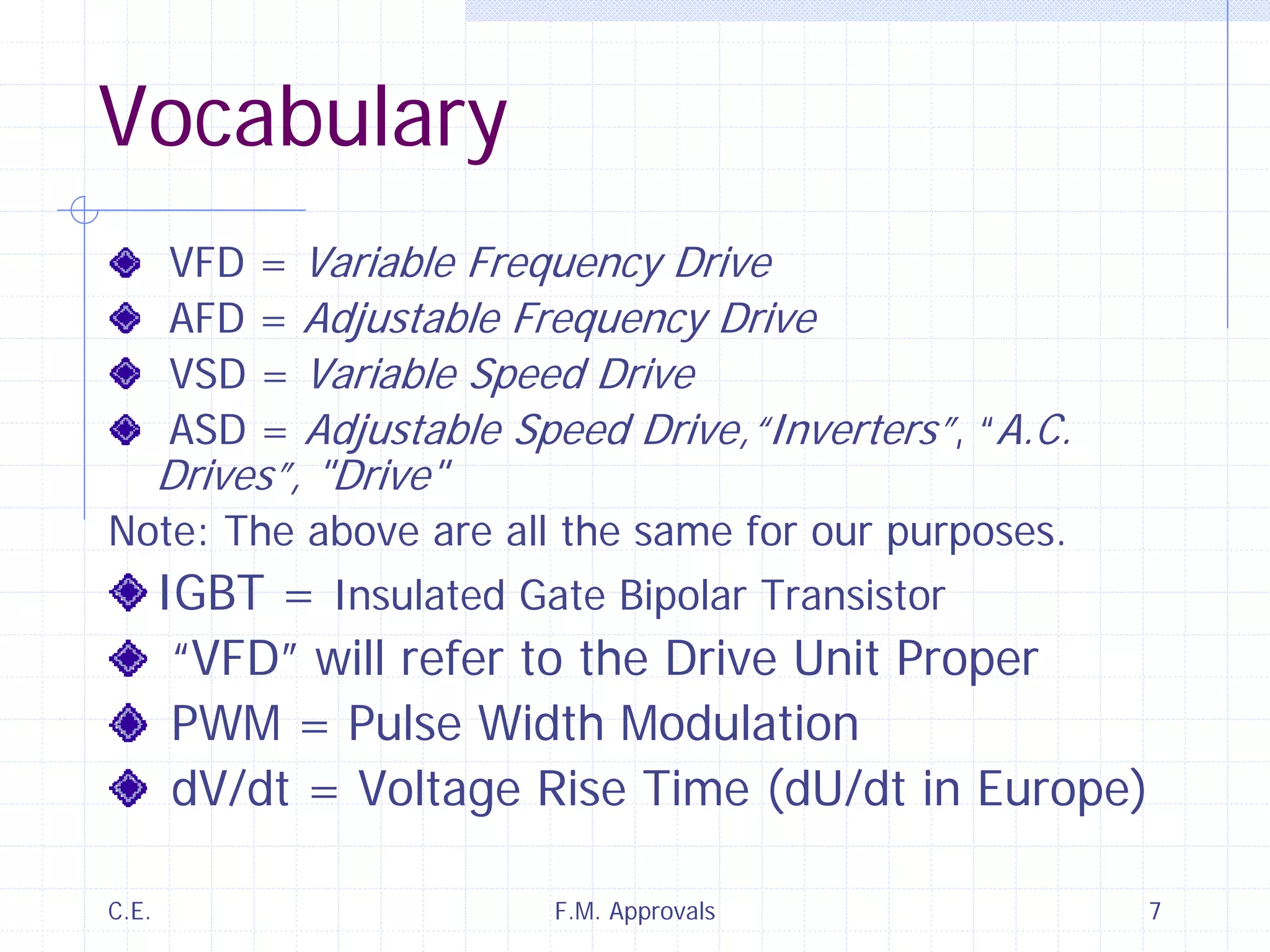
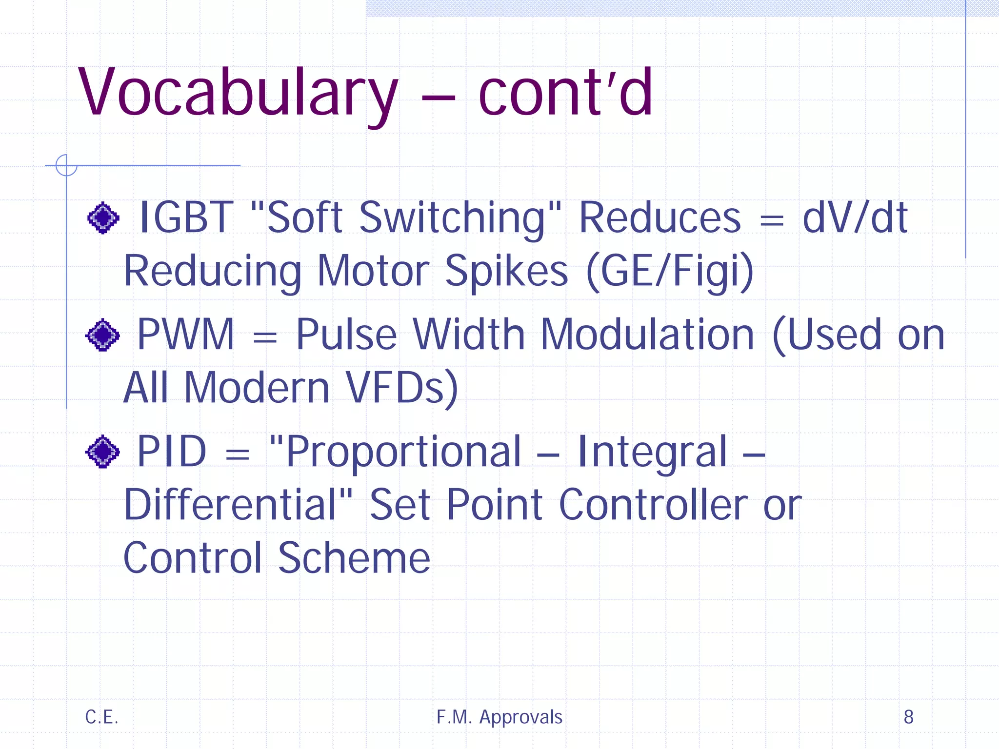
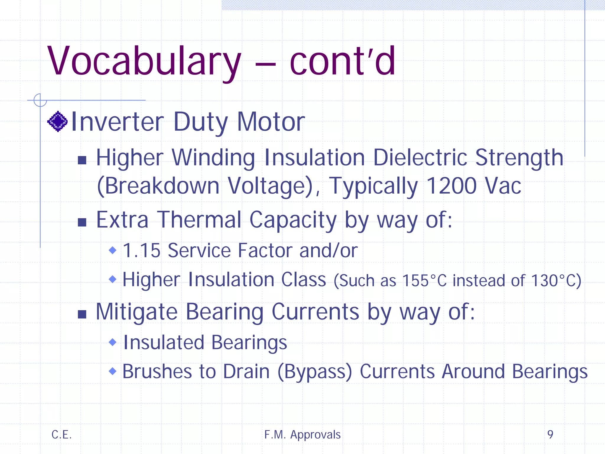
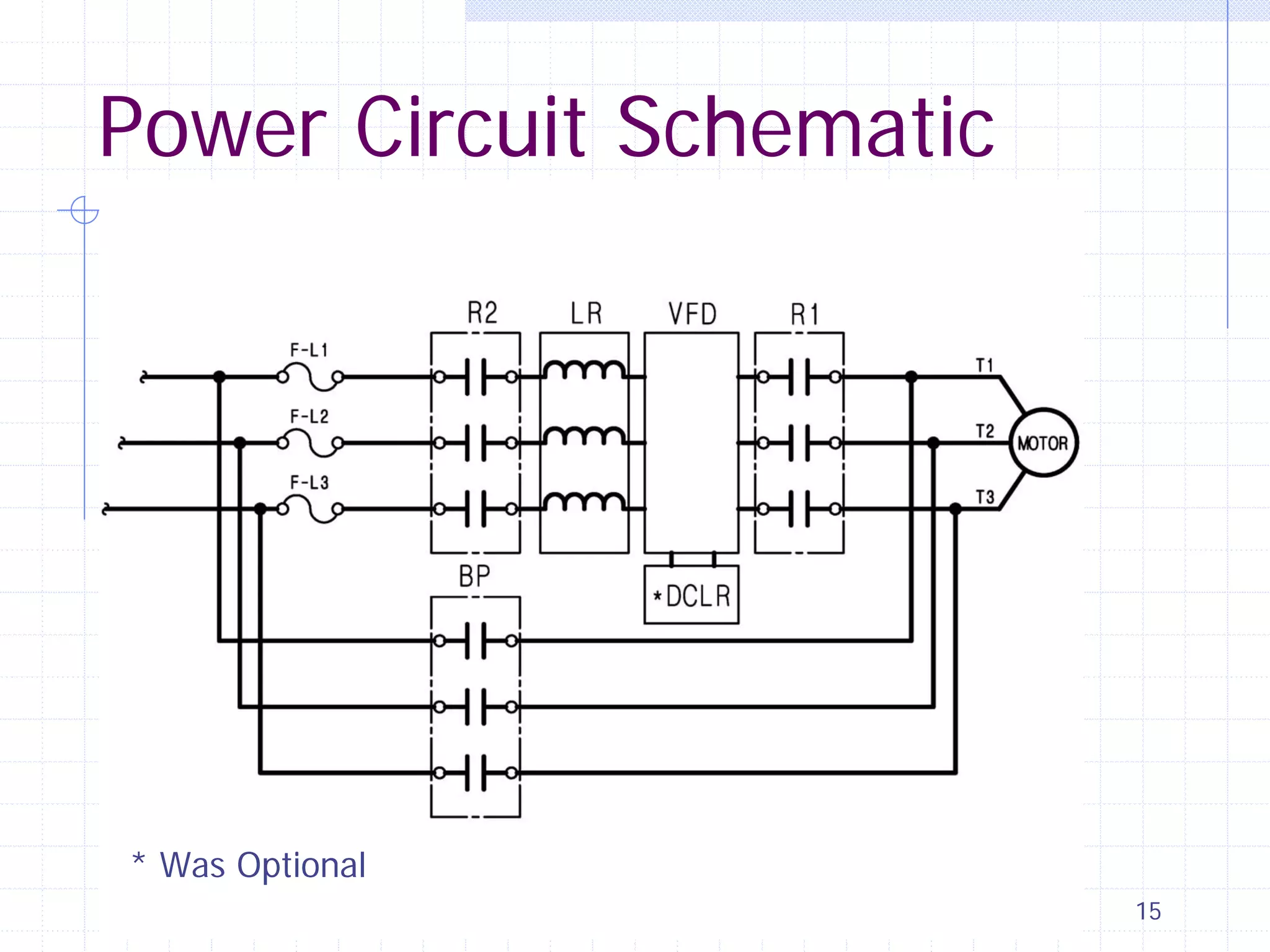
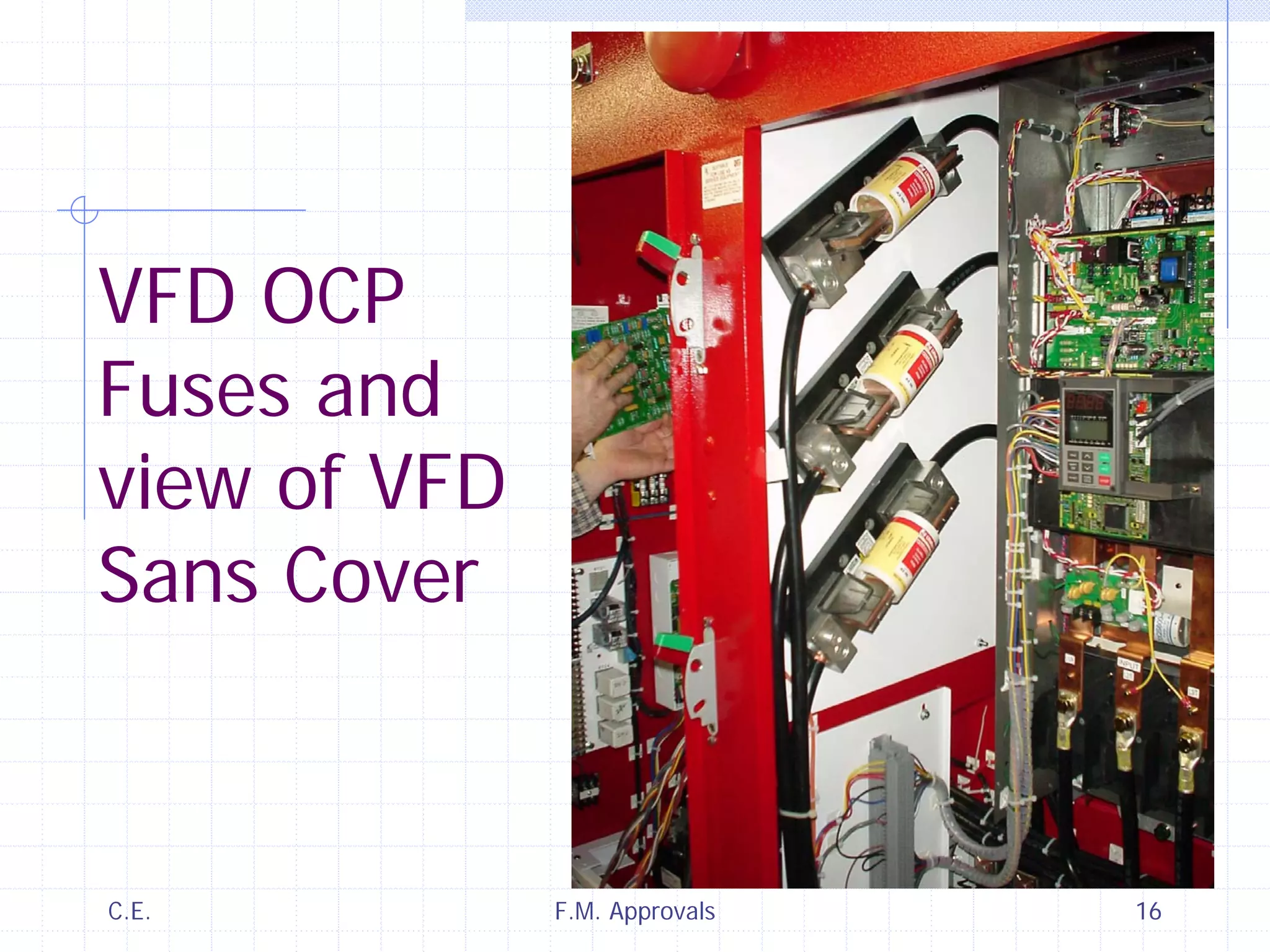
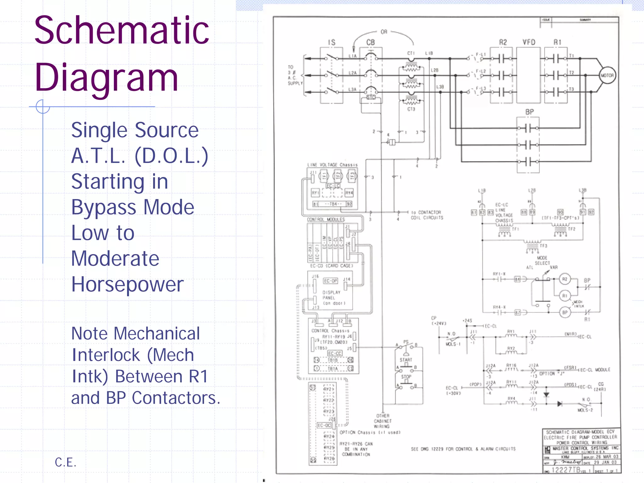
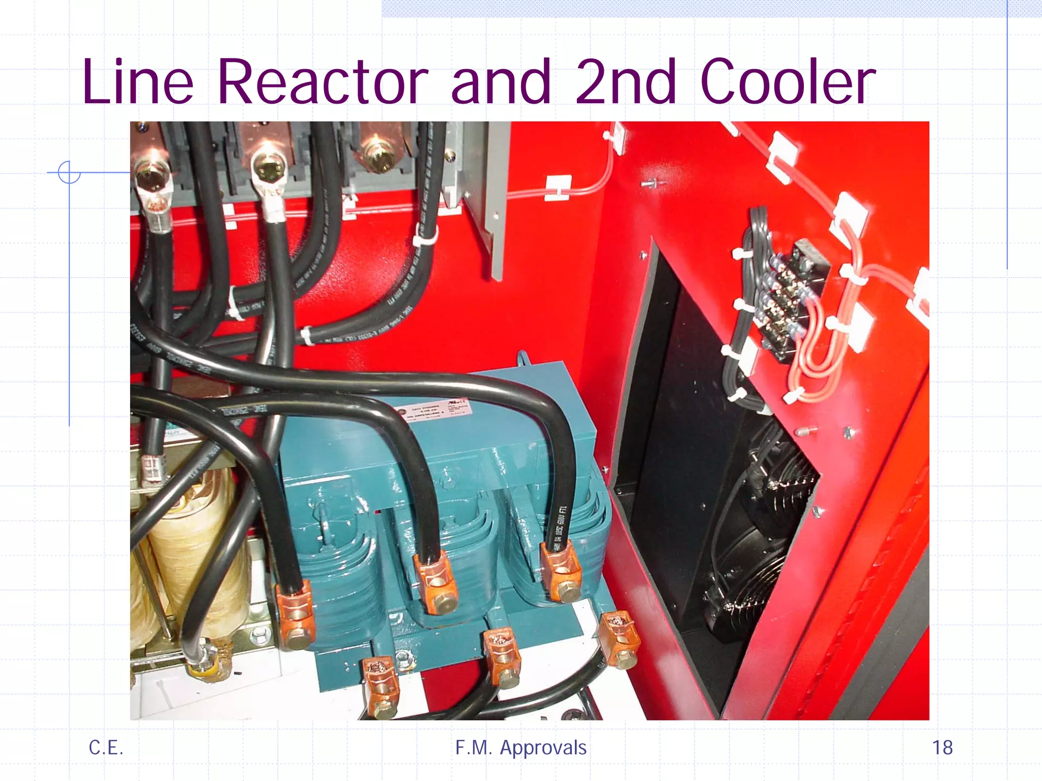
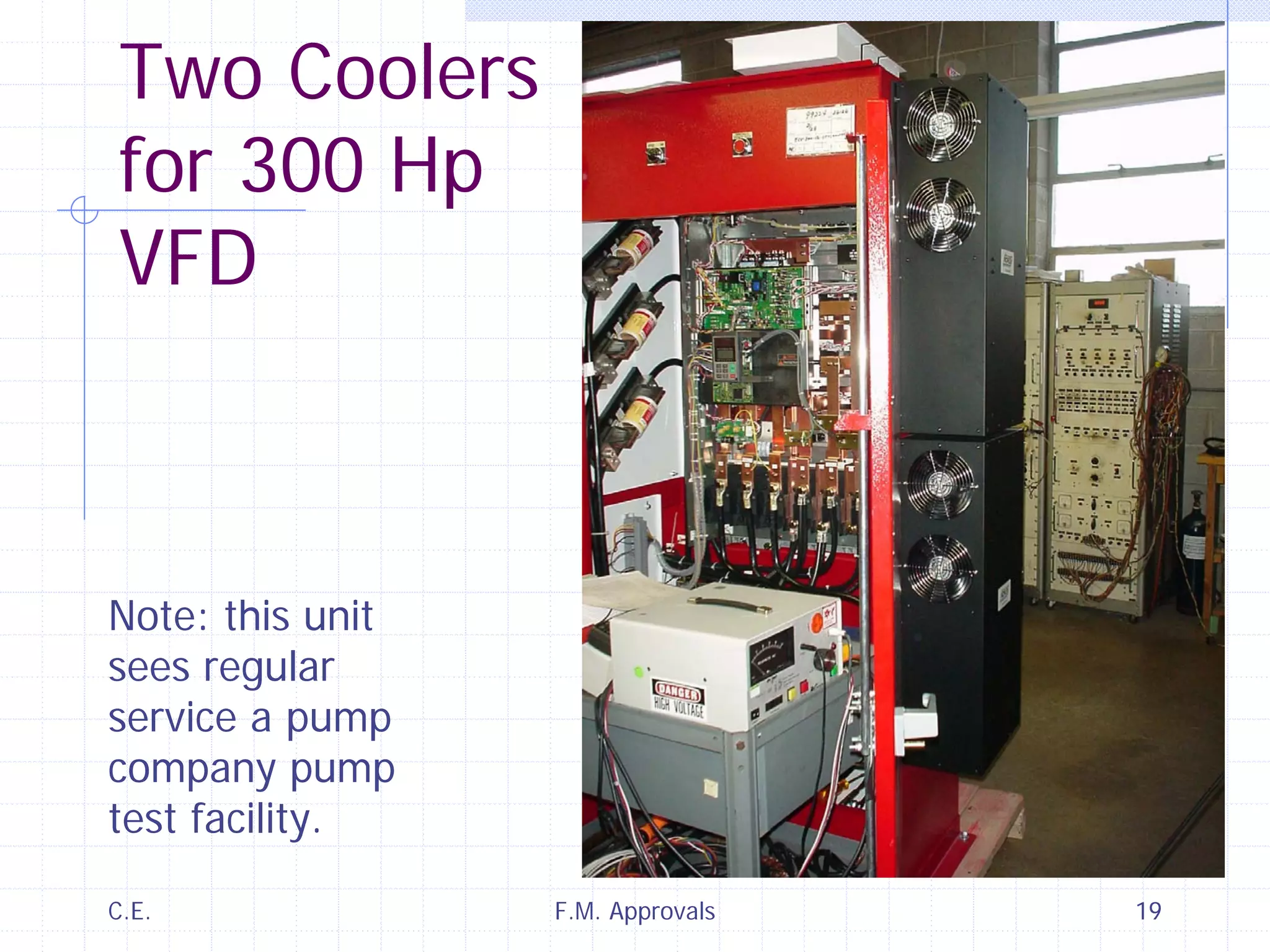
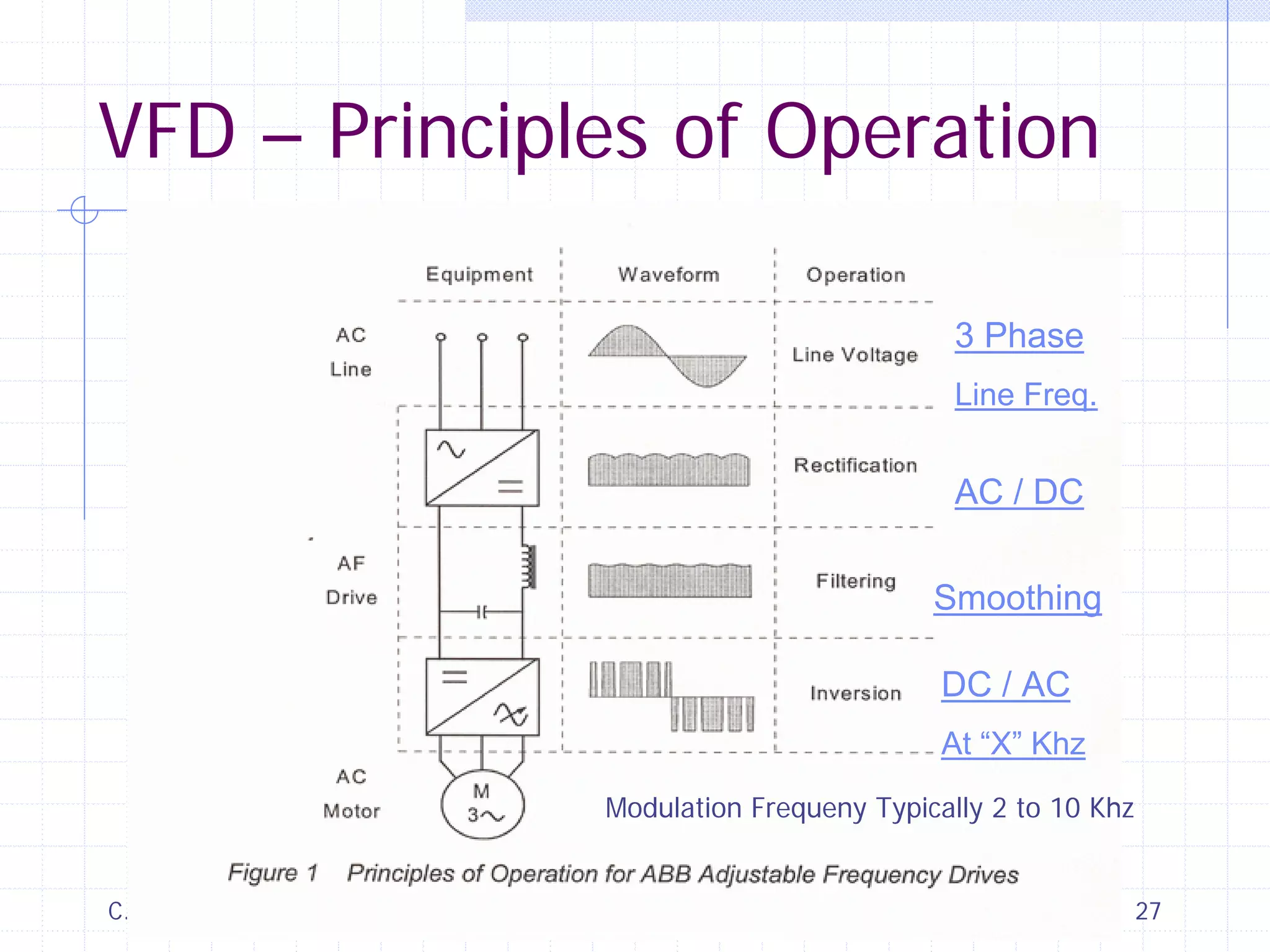
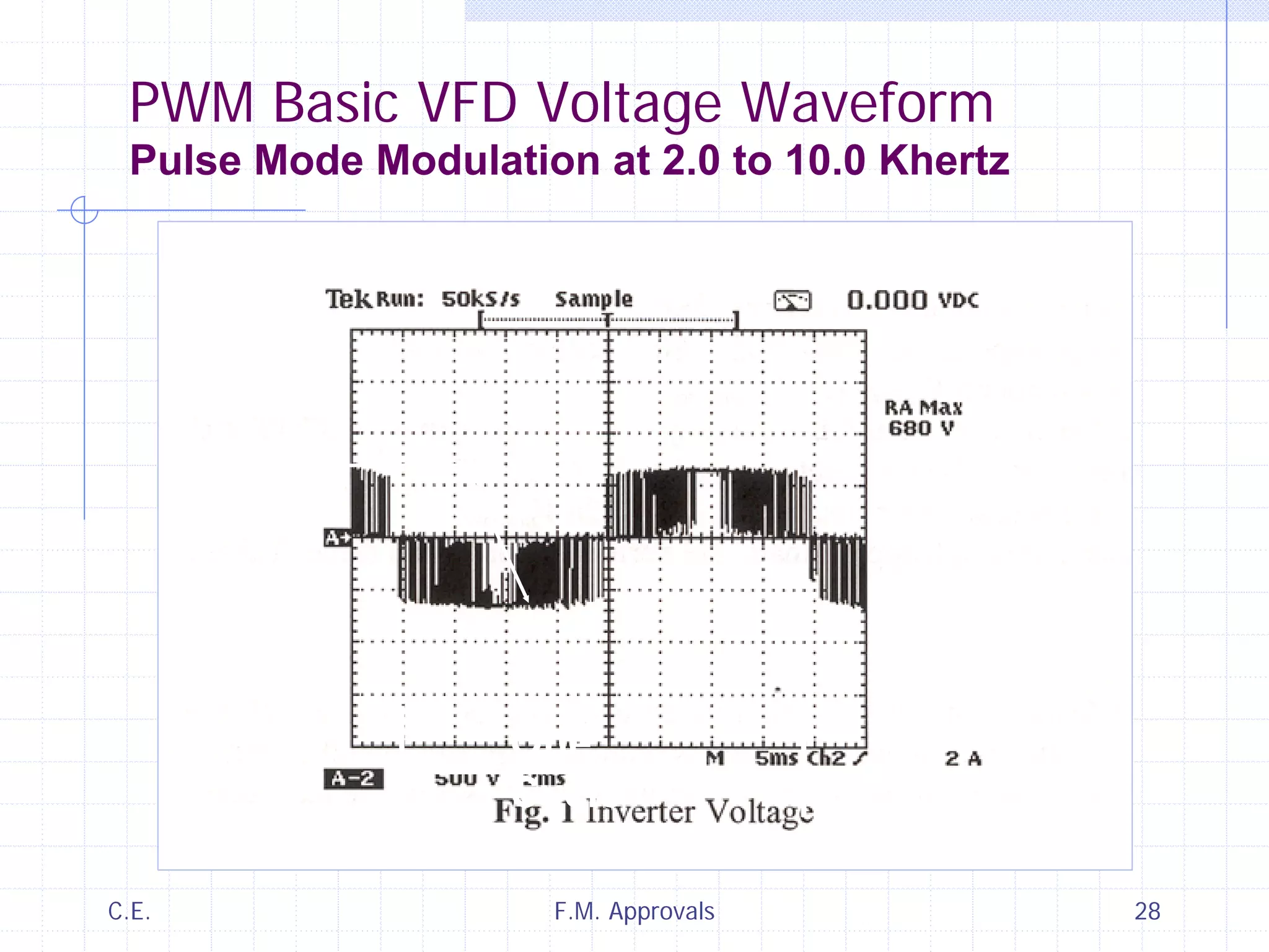
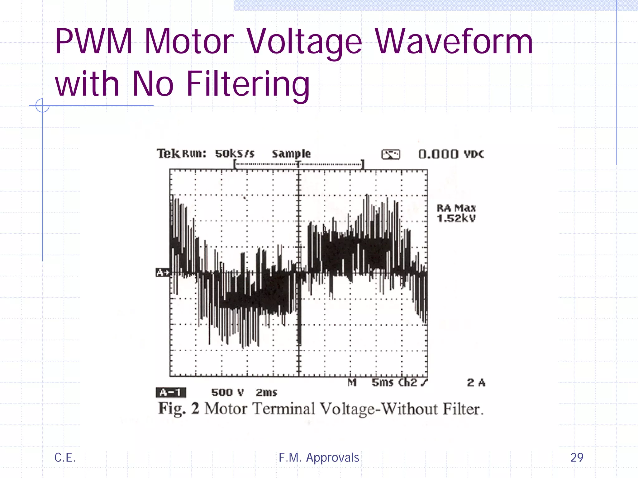
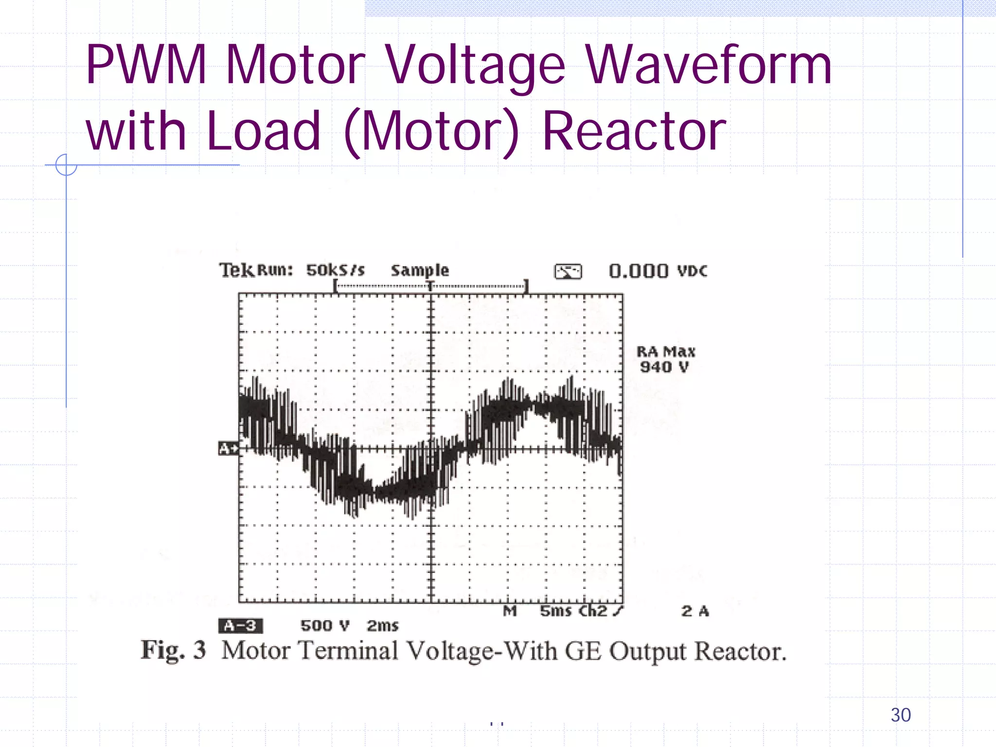
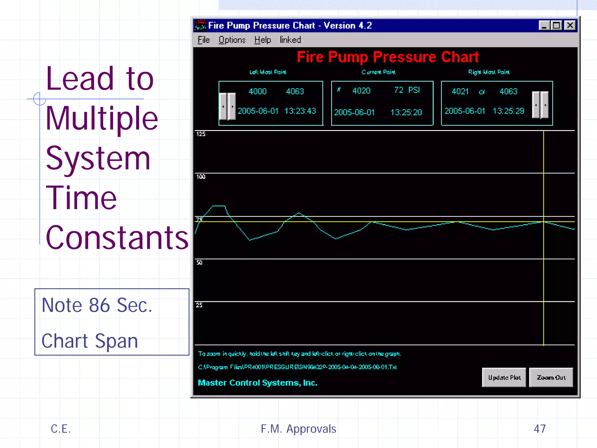
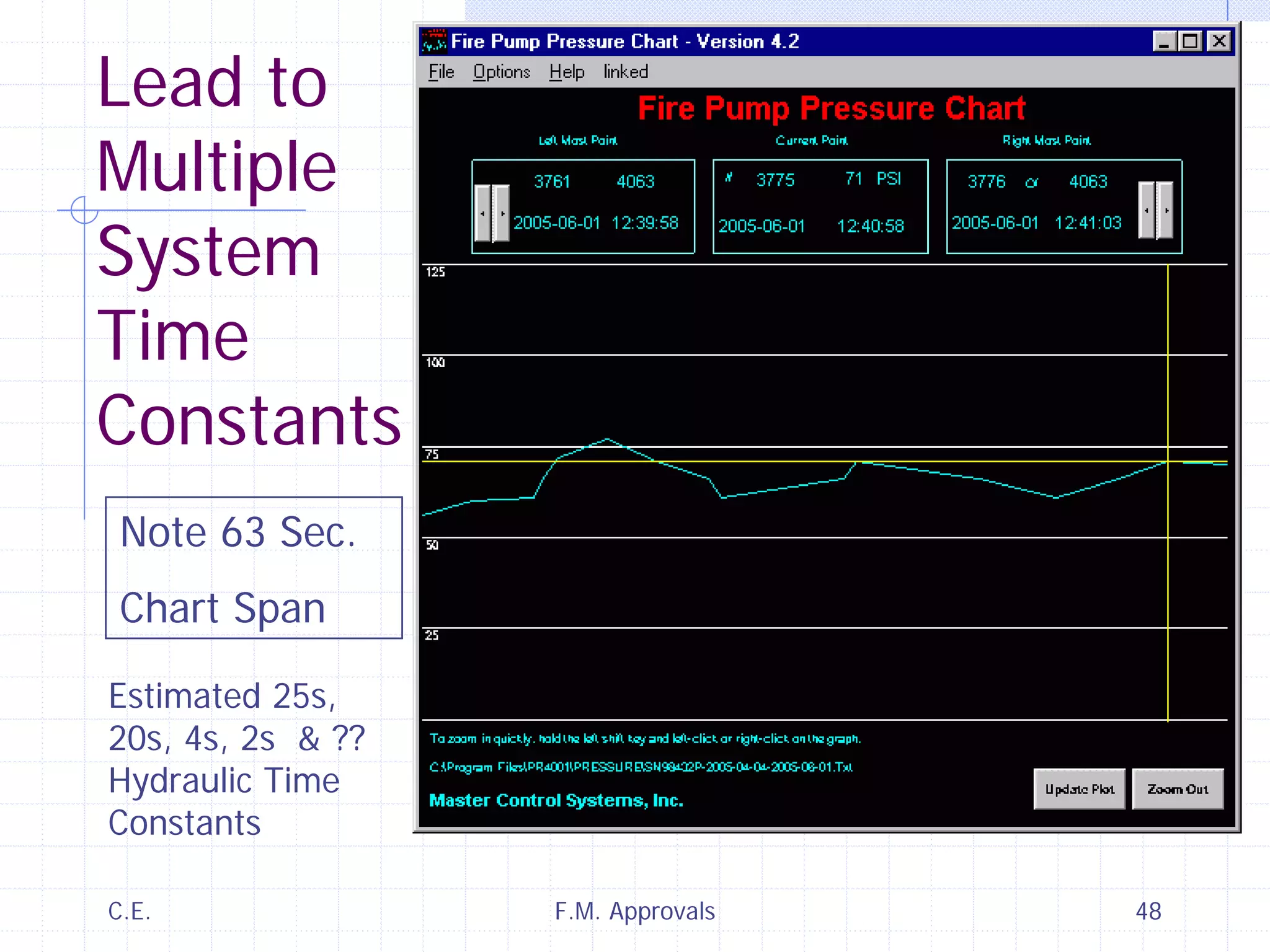
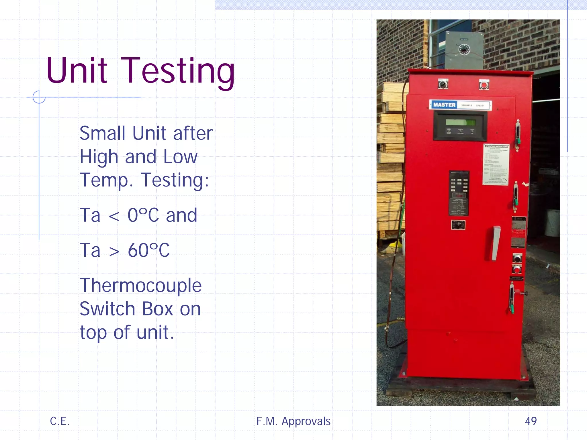
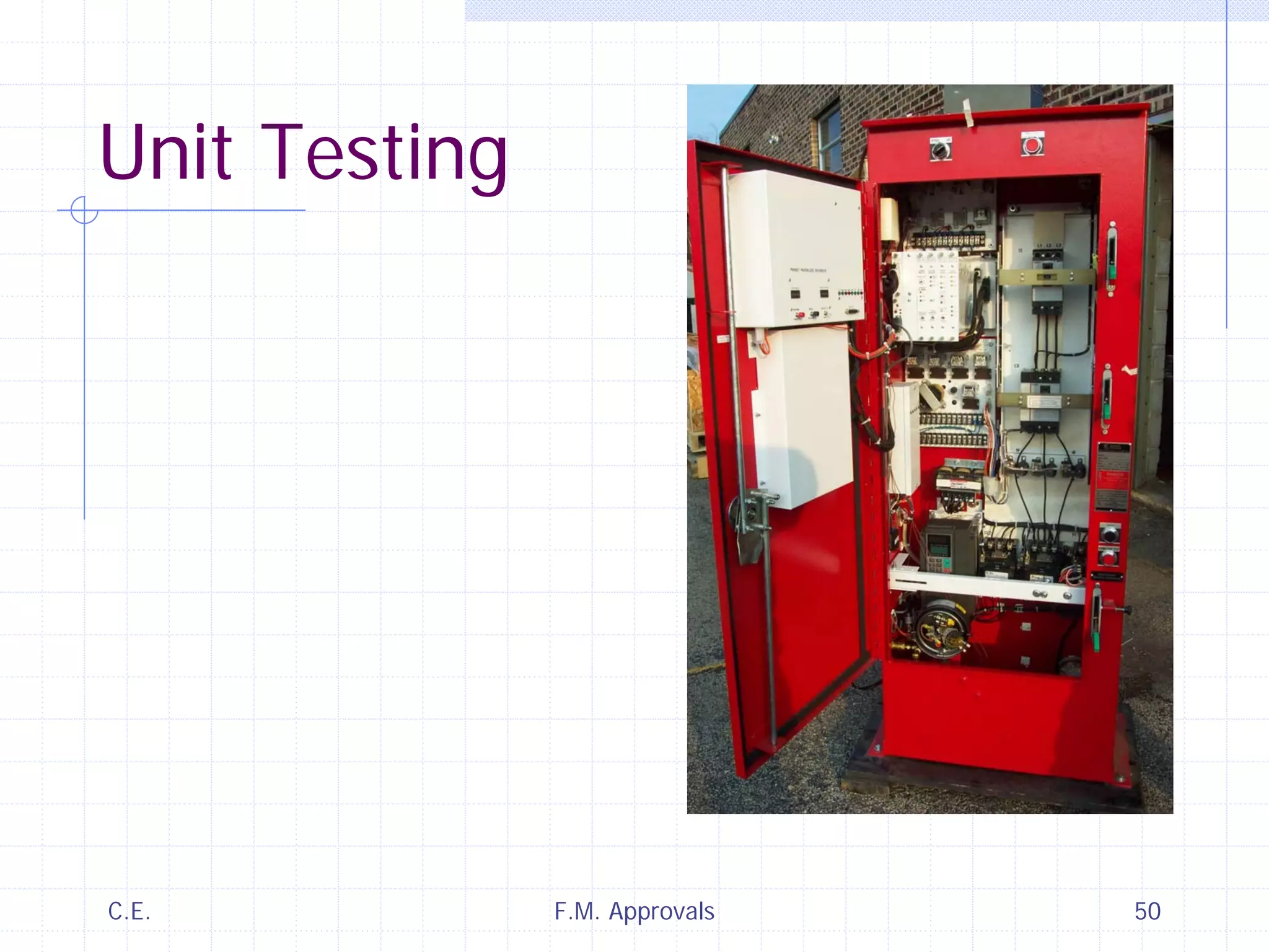
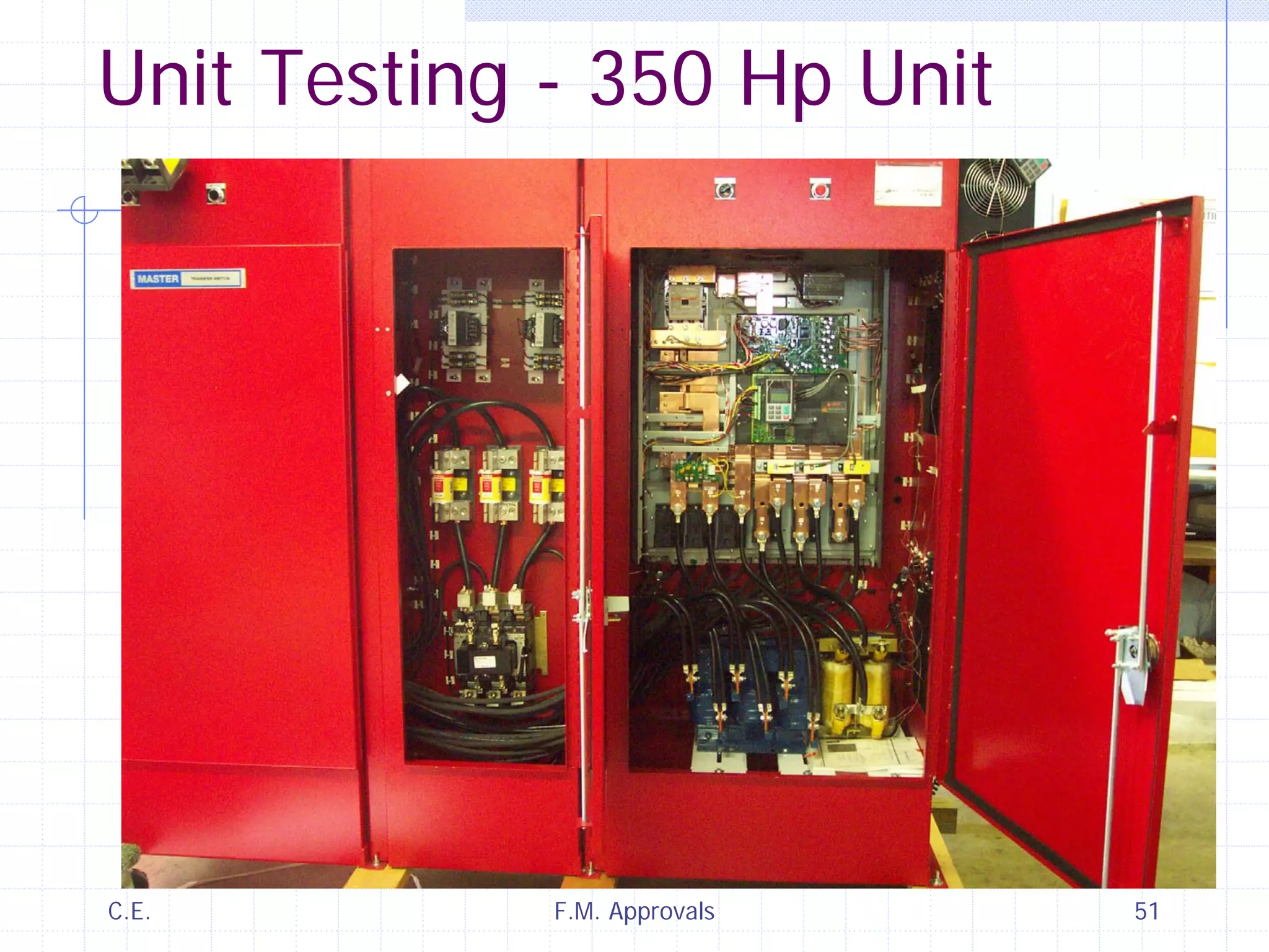
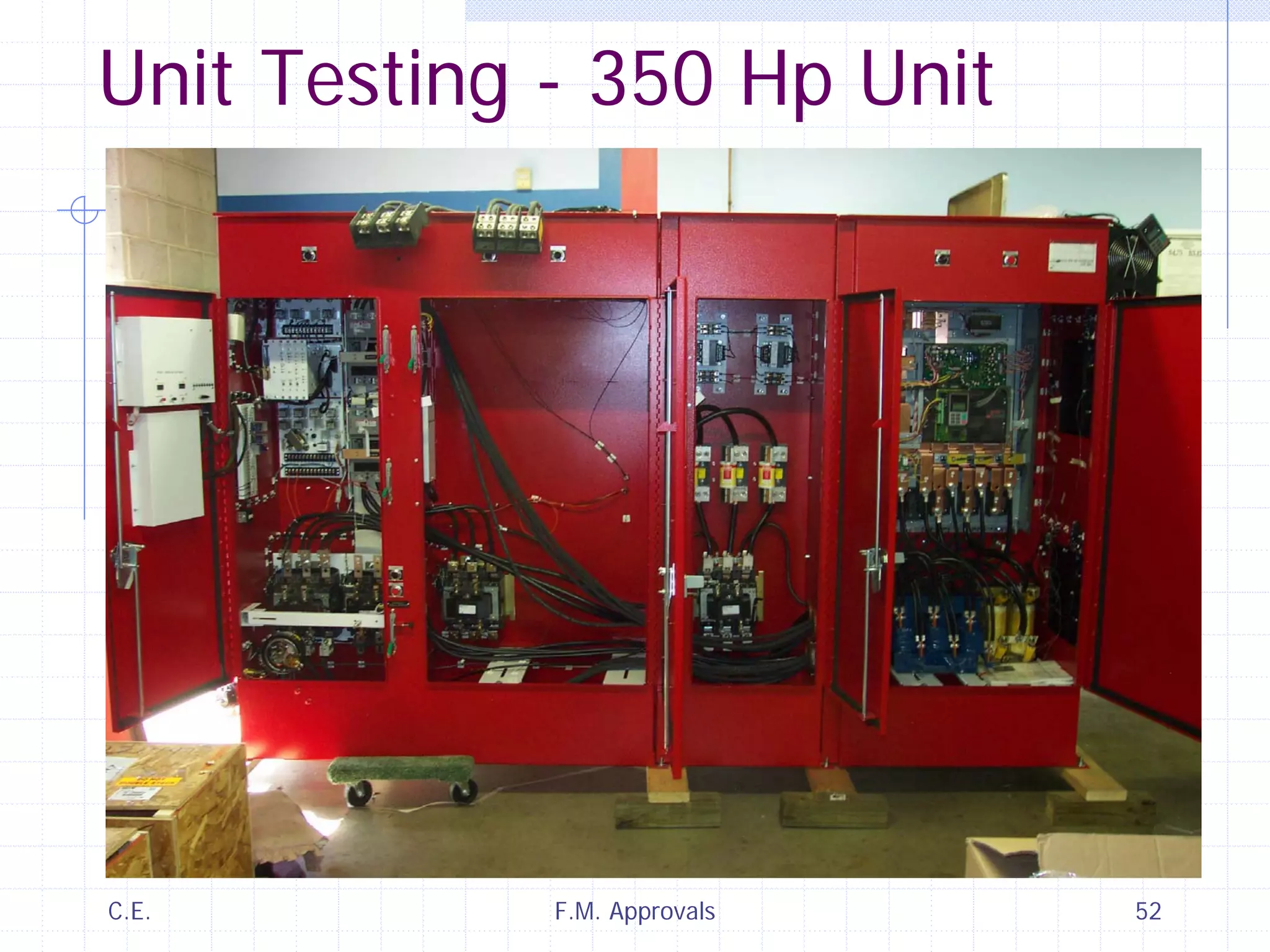
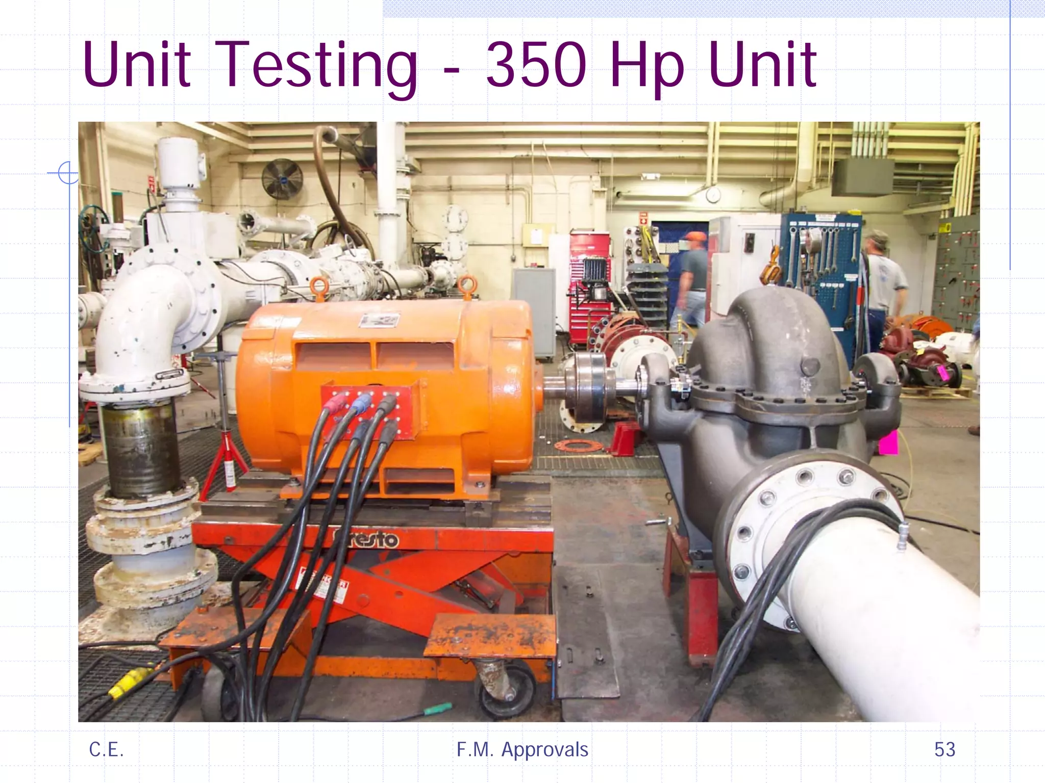
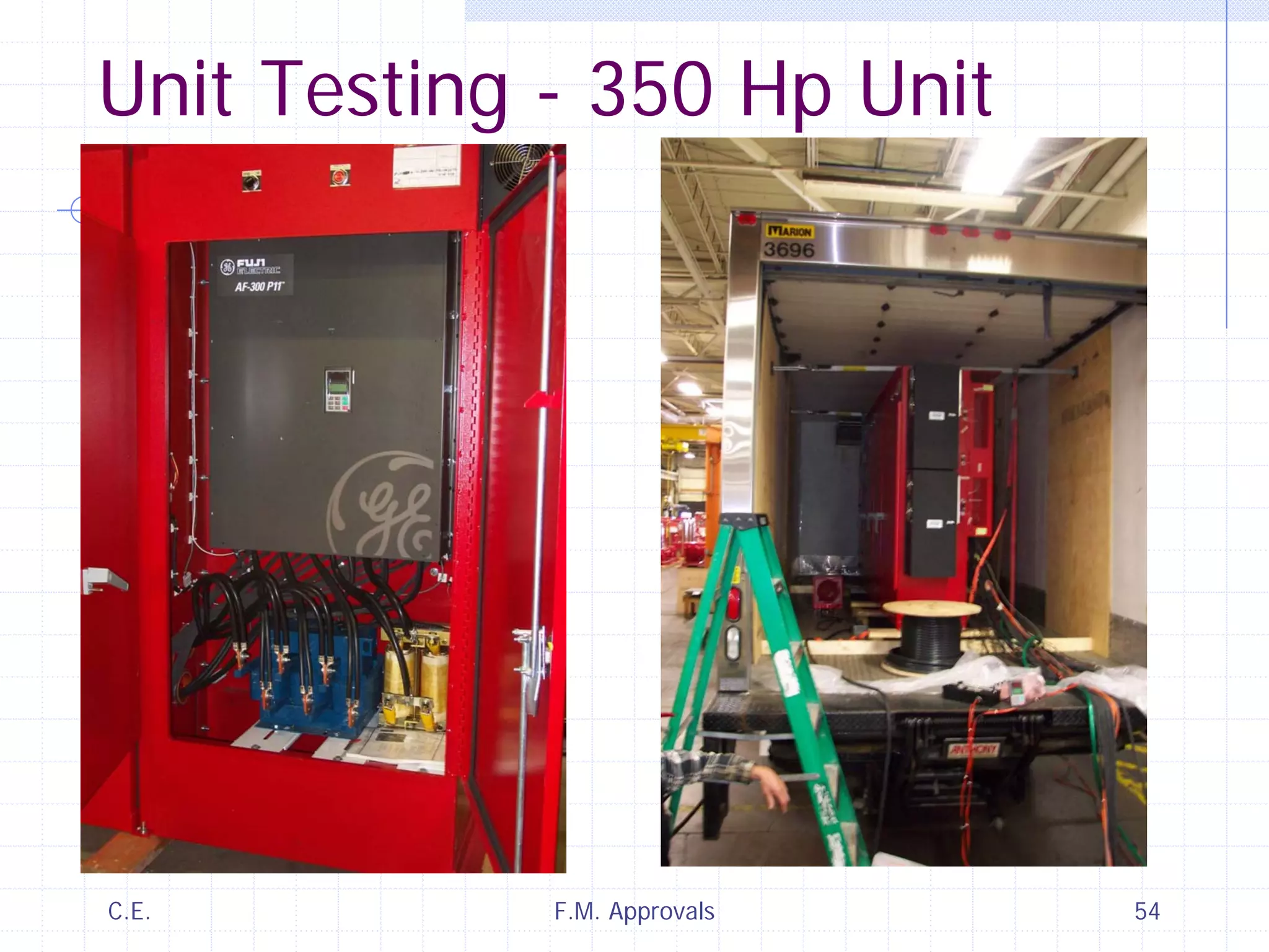
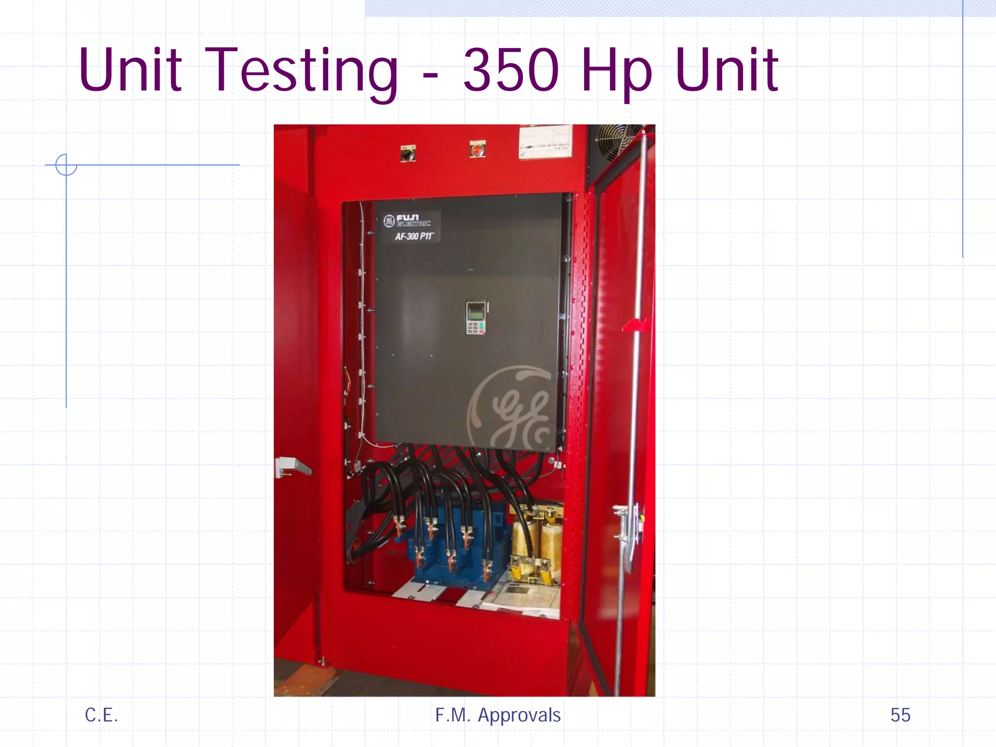
Variable Speed Fire Pump Controllers
- for -
F.M. Approvals
- by -
James S. Nasby
Columbia Engineering
C.E. F.M. Approvals 2
Topics to be Covered
VFD and Controller Elements
VFD Characteristics
Primary (Desired) Effects on Motor
Secondary (Undesired) Effects
On Motor
On Power Grid (Mains)
System Characteristics & Effects
Motor Requirements
Applications
Testing
C.E. F.M. Approvals 3
Model
ECV-250-46-*
250 Hp –
Single Source
A.T.L Start in
Bypass
C.E. F.M. Approvals 4
Model
ECV-250-46-*
250 Hp –
Single Source
A.T.L Start in
Bypass
C.E. F.M. Approvals 5
Model ECVRTZ-100-46-*
C.E. F.M. Approvals 6
Inside
View
of
Drive
Bay
D.C.
Link
Reactor
Line
Reactor
Cooler
CPT &
Fuses
C.E. F.M. Approvals 7
Vocabulary
VFD = Variable Frequency Drive
AFD = Adjustable Frequency Drive
VSD = Variable Speed Drive
ASD = Adjustable Speed Drive,“Inverters”, “A.C.
Drives”, "Drive"
Note: The above are all the same for our purposes.
IGBT = Insulated Gate Bipolar Transistor
“VFD” will refer to the Drive Unit Proper
PWM = Pulse Width Modulation
dV/dt = Voltage Rise Time (dU/dt in Europe)
C.E. F.M. Approvals 8
Vocabulary – cont’d
IGBT "Soft Switching" Reduces = dV/dt
Reducing Motor Spikes (GE/Figi)
PWM = Pulse Width Modulation (Used on
All Modern VFDs)
PID = "Proportional – Integral –
Differential" Set Point Controller or
Control Scheme
C.E. F.M. Approvals 9
Vocabulary – cont’d
Inverter Duty Motor
Higher Winding Insulation Dielectric Strength
(Breakdown Voltage), Typically 1200 Vac
Extra Thermal Capacity by way of:
1.15 Service Factor and/or
Higher Insulation Class (Such as 155°C instead of 130°C)
Mitigate Bearing Currents by way of:
Insulated Bearings
Brushes to Drain (Bypass) Currents Around Bearings
C.E. F.M. Approvals 10
Vocabulary – cont’d
Constant Torque Rating: For Mills and Take-
up Reel Drives and Positive Displacement
(Piston) Pumps
Where Rated Torque is Needed at Zero (or Near
Zero) Speed.
Variable Torque Rating: For Fans, Blowers,
Centrifugal Pumps & etc.
Where the Load Torque Varies with Speed (RPM).
E.g.: Low Torque at Zero (and Near Zero) Speeds.
C.E. F.M. Approvals 11
Vocabulary – cont’d
Set-Point = Desired Outcome
(e.g.: Desired Pressure)
System Response May Be One:
Oscillatory
Under Damped
Critically Damped (with or w/o Overshoot)
Over Damped
C.E. F.M. Approvals 12
System Response Curves
Under DampedOscillatory
(With Overshoot)
Over DampedCritically Damped
C.E. F.M. Approvals 13
Required Controller Elements
Controller Must be a Full Service Controller
Plus a VFD Unit
Plus VFD Fuses (at <299% of FLA)
Plus Load Side Isolation Contactor (interlocked)
Plus Line Side Isolation Contactor
Plus By-Pass (Main) Contactor
All Fully Rated (Horsepower Rated)
Line Reactor - 5% Minimum to:
Reduce Line Current Harmonics
Reduce Line Transients to the VFD
Reduce Capacitor Over-voltage Shutdown due to Line Spikes
and/or Surges
Note: All line spikes and surges get rectified regardless of
where they appear on the Waveform.
C.E. F.M. Approvals 14
Required Controller Elements - cont'd
Mechanical Interlock Between Bypass Contactor and
VFD Output Contactor to
Prevent Back Feeding VFD on Controller Defect since this will
cause the Main Fire Pump Circuit Breaker (C/B) to Trip. This
causes the Fire Pump to be off line (dead).
Means to Lock VFD and Starting Parameters
Typical VFD has over 150 settable parameters, many of which
will cause damage or no fire water if mis-set
PID to Control Pressure
Must be able to Control Time Constants and Dynamic
Characteristics to Avoid Cycling or Hydraulic System Damage
C.E. F.M. Approvals 15
Power Circuit Schematic
* Was Optional
C.E. F.M. Approvals 16
VFD OCP
Fuses and
view of VFD
Sans Cover
C.E. F.M. Approvals 17
Schematic
Diagram
Single Source
A.T.L. (D.O.L.)
Starting in
Bypass Mode
Low to
Moderate
Horsepower
Note Mechanical
Interlock (Mech
Intk) Between R1
and BP Contactors.
C.E. F.M. Approvals 18
Line Reactor and 2nd Cooler
C.E. F.M. Approvals 19
Two Coolers
for 300 Hp
VFD
Note: this unit
sees regular
service a pump
company pump
test facility.
C.E. F.M. Approvals 20
Must Include a Complete
Full Service Fire Pump Controller
Standard Full Service Circuitry and
Components
Standard Mechanical Manual Operator
Mode Switch for Full Speed Bypass Operation
Easier Commissioning, Servicing and for Back-up
Automatic Fire Protection
Standard Pressure Switch/Transducer
Bypass and Start use the Same Switch -or-
Separate Swtiches used (some Mfrs)
Separate (2nd) Transducer for Recording (one Mfr.)
C.E. F.M. Approvals 21
Close-up of Pressure Switch and
Both Pressure Transducers
C.E. F.M. Approvals 22
External Wiring Diagram
C.E. F.M. Approvals 23
Optional Controller Elements
Line Side EMI / RFI (EMC) Filter
Load Side (Motor) Output Reactor
Load Side (Motor) dV/dt Filter
D.C. Link Reactor (Standard with Some)
Advanced Operator Display Panels
Network Connection
C.E. F.M. Approvals 24
VFD – Principles of Operation
Three Main Sections:
Three Phase Rectifier Section (AC/DC)
D.C. Filter Section - D.C. Bus Capacitors
(Bus Cap’s)
Inverter Section (DC/AC): Pulse Width
Modulator (PWM)
Modern VFD’s use IGBT’s for Inverter
Inverter Typically Runs at 2 to 6 Kilohertz
C.E. F.M. Approvals 25
VFD = Motor Running Only
(No Motor Starting Region)
Typical Motor Torque and Pump Torque Curves
C.E. F.M. Approvals 26
Lower Frequency Shortens Curve
This point Moves Left
Relative to Frequency
100% = 60 Hz or 59 or 30 or any Frequency
C.E. F.M. Approvals 27
3 Phase
Line Freq.
AC / DC
Smoothing
DC / AC
At “X” Khz
VFD – Principles of Operation
Modulation Frequeny Typically 2 to 10 Khz
C.E. F.M. Approvals 28
PWM Basic VFD Voltage Waveform
Pulse Mode Modulation at 2.0 to 10.0 Khertz
2 Khz
One
Cycle
C.E. F.M. Approvals 29
PWM Motor Voltage Waveform
with No Filtering
C.E. F.M. Approvals 30
PWM Motor Voltage Waveform
with Load (Motor) Reactor
C.E. F.M. Approvals 31
PWM Motor Voltage Waveform
with Motor Filter
C.E. F.M. Approvals 32
Motor Electrical Measurements
Special Metering Required
due to the High Voltage
and Frequency
C.E. F.M. Approvals 33
Controller Operation
1) Pressure Switch Trips
2) Contactor R1 and R2 Close
3) Signal VFD to Start
4) Begin Timing for VFD Ready Signal
(3-5 Sec.)
5) Begin Pressure Switch Tripped Timing
(approx. 20 Seconds)
6) VFD Sends “Drive Ready” Signal -or-
C.E. F.M. Approvals 34
Controller Operation – cont’d
7) Bypass Operation Begins after Restart Delay
-- or --
8) VFD Begins Motor Acceleration
9) VFD adjust motor speed to Achieve Desired
Pump Pressure Set-Point
10) Pump Builds Up Sufficient Pressure to Reset
the Pressure Switch within 20 Seconds -or-
11) Begin Bypass Operation (Same as # 7 above)
C.E. F.M. Approvals 35
Controller Operation – cont’d
12) VFD Modulates Motor Speed Using its PID
to Maintain System Pressure at Desires Set-
Point Even with Flow and Suction Pressure
Fluctuations -or-
13) Pressure Switch Re-Trips and Pressure
Switch Tripped Timer Begins Timing Cycle
(Again)
14) After 20 Seconds, By-Pass Operation Begins
(same as #7 above)
15) By-Pass Operation is Manual Reset
C.E. F.M. Approvals 36
Bypass Starting Methods
Full Voltage (A-T-L)
Primary Reactor
Soft Starter
Some Controllers also Provide Soft Stop
(extra circuitry needed for the Soft Stop Function)
Some Units will Ramp Up to at Lease an Idle Speed
and continue to increase speed until the pressure
demand is met.
C.E. F.M. Approvals 37
VFD Starting Characteristics
All VFDs provide Soft Starting (Ramp-up)
Max. Torque/Current can be set
150% Starting and 110% Running are Typical
System Must be Suitable for Bypass Mode Starting
Some Controllers also Provide Soft Stop
(extra circuitry needed for the Soft Stop Function)
Some Units will Ramp Up to at Lease an Idle Speed
and continue to increase speed until the pressure
demand is met.
C.E. F.M. Approvals 38
Design Considerations
Capacitor Overvoltage Shutdown
This is a Lockout Condition, Manual Reset is always
Required.
480 Vac x 1.414 = 678 + 10% = 747 Vac. Better VFD's
don't shut down until the capacitor voltage exceeds 800 Vac.
Lesser ones shutdown at 750 Vac or less.
VFD Shutdown Temperature.
Better VFDs don't shutdown until 70ºC and can be restarted
with no damage or degradation
VFD Pollution Degree Requirements must be met.
Cooling should be Closed Loop (no Venting Pump Room Air
into Controller.
C.E. F.M. Approvals 39
Design Considerations - cont'd
VFD OCP Must be Fully Selectively Coordinated with
the Main Fire Pump Circuit Breaker (C/B)
Said OCP will Most Likely be Fuses
Coordination with the is Critical to Avoid Tripping which Kills
the Bypass Mode.
Fuses (OCP) must trip before the 300% point
Fuses must trip in less than 8 seconds at Locked Rotor
Current
Fuses must still be large enough to hold with the Maximum
normal VFD input current including harmonic content.
The Fuse curve must never touch the C/B curve to avoid any
risk of tripping.
Fuse tolerance must also be considered. The plus tolerance
on the fuse curve can lead to tripping of the F.P. C/B.
C.E. F.M. Approvals 40
Design Considerations - cont'd
Fuses must be calculated for Each and Every
controller Hp and Voltage (E.g.: Each nominal
FLA).
Controller cooling must keep the VFD within is
maximum rated temperature.
A 50ºC VFD will require the cooling to keep the
temperature rise to no more than 10ºC for a
Controller Rated Maximum Temperature of 40ºC.
A VFD rated at only 40ºC will require de-rating
unless refrigeration is allowed.
C.E. F.M. Approvals 41
Design Considerations - cont'd
Polution Degree Rating of the VFD must not
be exceeded. This will typically require a non-
vented NEMA 12 (U.L. Type 12) or better
enclosure and cooling means.
Internal Controller Wiring in the VFD input
path must be sized for the harmonic content
of the VFD.
Successful Installations the Mfr. to ascertain
and check the system hydraulic time constants
and set the PID parameters accordingly.
C.E. F.M. Approvals 42
Application Considerations
Additional Considerations:
* The controller is UL listed for fire pump applications.
* The enclosure is rated for NEMA 12.
* Maximum ambient must not exceed controller (marked) rating.
* Mfr's vent air clearance spaces and service spaces must be adheared to.
* The motor must be suitable for use with a variable speed drive.
* Motor current draw must not exceed 100% of FLA, even though the motor
may have a 1.15 or higher service factor
* A gen-set must be suitable for use with a variable speed drive.
* The power source must be capable of bypass mode Starting method.
* The pump and motor must be rigidly coupled.
* The pump and motor must be properly grouted.
* A relief valve is required for emergency operation unless system pressure
can not be exceed at churn and full speed and max. suction pressure.
C.E. F.M. Approvals 43
Multi-Acre
Multi-
Building
Campus
…
C.E. F.M. Approvals 44
…and Back-up Distant Water Supply…
C.E. F.M. Approvals 45
Lead to
Multiple
System
Time
Constants
Note
253 Second
Chart Span
C.E. F.M. Approvals 46
Note 151 Sec.
Chart Span
Lead to
Multiple
System
Time
Constants
C.E. F.M. Approvals 47
Note 86 Sec.
Chart Span
Lead to
Multiple
System
Time
Constants
C.E. F.M. Approvals 48
Note 63 Sec.
Chart Span
Lead to
Multiple
System
Time
Constants
Estimated 25s,
20s, 4s, 2s & ??
Hydraulic Time
Constants
C.E. F.M. Approvals 49
Unit Testing
Small Unit after
High and Low
Temp. Testing:
Ta < 0ºC and
Ta > 60ºC
Thermocouple
Switch Box on
top of unit.
C.E. F.M. Approvals 50
Unit Testing
C.E. F.M. Approvals 51
Unit Testing - 350 Hp Unit
C.E. F.M. Approvals 52
Unit Testing - 350 Hp Unit
C.E. F.M. Approvals 53
Unit Testing - 350 Hp Unit
C.E. F.M. Approvals 54
Unit Testing - 350 Hp Unit
C.E. F.M. Approvals 55
Unit Testing - 350 Hp Unit
Questions?

Variable speed fire pump controllers

  • 1.
    Variable Speed FirePump Controllers - for - F.M. Approvals - by - James S. Nasby Columbia Engineering
  • 2.
    C.E. F.M. Approvals2 Topics to be Covered VFD and Controller Elements VFD Characteristics Primary (Desired) Effects on Motor Secondary (Undesired) Effects On Motor On Power Grid (Mains) System Characteristics & Effects Motor Requirements Applications Testing
  • 3.
    C.E. F.M. Approvals3 Model ECV-250-46-* 250 Hp – Single Source A.T.L Start in Bypass
  • 4.
    C.E. F.M. Approvals4 Model ECV-250-46-* 250 Hp – Single Source A.T.L Start in Bypass
  • 5.
    C.E. F.M. Approvals5 Model ECVRTZ-100-46-*
  • 6.
    C.E. F.M. Approvals6 Inside View of Drive Bay D.C. Link Reactor Line Reactor Cooler CPT & Fuses
  • 7.
    C.E. F.M. Approvals7 Vocabulary VFD = Variable Frequency Drive AFD = Adjustable Frequency Drive VSD = Variable Speed Drive ASD = Adjustable Speed Drive,“Inverters”, “A.C. Drives”, "Drive" Note: The above are all the same for our purposes. IGBT = Insulated Gate Bipolar Transistor “VFD” will refer to the Drive Unit Proper PWM = Pulse Width Modulation dV/dt = Voltage Rise Time (dU/dt in Europe)
  • 8.
    C.E. F.M. Approvals8 Vocabulary – cont’d IGBT "Soft Switching" Reduces = dV/dt Reducing Motor Spikes (GE/Figi) PWM = Pulse Width Modulation (Used on All Modern VFDs) PID = "Proportional – Integral – Differential" Set Point Controller or Control Scheme
  • 9.
    C.E. F.M. Approvals9 Vocabulary – cont’d Inverter Duty Motor Higher Winding Insulation Dielectric Strength (Breakdown Voltage), Typically 1200 Vac Extra Thermal Capacity by way of: 1.15 Service Factor and/or Higher Insulation Class (Such as 155°C instead of 130°C) Mitigate Bearing Currents by way of: Insulated Bearings Brushes to Drain (Bypass) Currents Around Bearings
  • 10.
    C.E. F.M. Approvals10 Vocabulary – cont’d Constant Torque Rating: For Mills and Take- up Reel Drives and Positive Displacement (Piston) Pumps Where Rated Torque is Needed at Zero (or Near Zero) Speed. Variable Torque Rating: For Fans, Blowers, Centrifugal Pumps & etc. Where the Load Torque Varies with Speed (RPM). E.g.: Low Torque at Zero (and Near Zero) Speeds.
  • 11.
    C.E. F.M. Approvals11 Vocabulary – cont’d Set-Point = Desired Outcome (e.g.: Desired Pressure) System Response May Be One: Oscillatory Under Damped Critically Damped (with or w/o Overshoot) Over Damped
  • 12.
    C.E. F.M. Approvals12 System Response Curves Under DampedOscillatory (With Overshoot) Over DampedCritically Damped
  • 13.
    C.E. F.M. Approvals13 Required Controller Elements Controller Must be a Full Service Controller Plus a VFD Unit Plus VFD Fuses (at <299% of FLA) Plus Load Side Isolation Contactor (interlocked) Plus Line Side Isolation Contactor Plus By-Pass (Main) Contactor All Fully Rated (Horsepower Rated) Line Reactor - 5% Minimum to: Reduce Line Current Harmonics Reduce Line Transients to the VFD Reduce Capacitor Over-voltage Shutdown due to Line Spikes and/or Surges Note: All line spikes and surges get rectified regardless of where they appear on the Waveform.
  • 14.
    C.E. F.M. Approvals14 Required Controller Elements - cont'd Mechanical Interlock Between Bypass Contactor and VFD Output Contactor to Prevent Back Feeding VFD on Controller Defect since this will cause the Main Fire Pump Circuit Breaker (C/B) to Trip. This causes the Fire Pump to be off line (dead). Means to Lock VFD and Starting Parameters Typical VFD has over 150 settable parameters, many of which will cause damage or no fire water if mis-set PID to Control Pressure Must be able to Control Time Constants and Dynamic Characteristics to Avoid Cycling or Hydraulic System Damage
  • 15.
    C.E. F.M. Approvals15 Power Circuit Schematic * Was Optional
  • 16.
    C.E. F.M. Approvals16 VFD OCP Fuses and view of VFD Sans Cover
  • 17.
    C.E. F.M. Approvals17 Schematic Diagram Single Source A.T.L. (D.O.L.) Starting in Bypass Mode Low to Moderate Horsepower Note Mechanical Interlock (Mech Intk) Between R1 and BP Contactors.
  • 18.
    C.E. F.M. Approvals18 Line Reactor and 2nd Cooler
  • 19.
    C.E. F.M. Approvals19 Two Coolers for 300 Hp VFD Note: this unit sees regular service a pump company pump test facility.
  • 20.
    C.E. F.M. Approvals20 Must Include a Complete Full Service Fire Pump Controller Standard Full Service Circuitry and Components Standard Mechanical Manual Operator Mode Switch for Full Speed Bypass Operation Easier Commissioning, Servicing and for Back-up Automatic Fire Protection Standard Pressure Switch/Transducer Bypass and Start use the Same Switch -or- Separate Swtiches used (some Mfrs) Separate (2nd) Transducer for Recording (one Mfr.)
  • 21.
    C.E. F.M. Approvals21 Close-up of Pressure Switch and Both Pressure Transducers
  • 22.
    C.E. F.M. Approvals22 External Wiring Diagram
  • 23.
    C.E. F.M. Approvals23 Optional Controller Elements Line Side EMI / RFI (EMC) Filter Load Side (Motor) Output Reactor Load Side (Motor) dV/dt Filter D.C. Link Reactor (Standard with Some) Advanced Operator Display Panels Network Connection
  • 24.
    C.E. F.M. Approvals24 VFD – Principles of Operation Three Main Sections: Three Phase Rectifier Section (AC/DC) D.C. Filter Section - D.C. Bus Capacitors (Bus Cap’s) Inverter Section (DC/AC): Pulse Width Modulator (PWM) Modern VFD’s use IGBT’s for Inverter Inverter Typically Runs at 2 to 6 Kilohertz
  • 25.
    C.E. F.M. Approvals25 VFD = Motor Running Only (No Motor Starting Region) Typical Motor Torque and Pump Torque Curves
  • 26.
    C.E. F.M. Approvals26 Lower Frequency Shortens Curve This point Moves Left Relative to Frequency 100% = 60 Hz or 59 or 30 or any Frequency
  • 27.
    C.E. F.M. Approvals27 3 Phase Line Freq. AC / DC Smoothing DC / AC At “X” Khz VFD – Principles of Operation Modulation Frequeny Typically 2 to 10 Khz
  • 28.
    C.E. F.M. Approvals28 PWM Basic VFD Voltage Waveform Pulse Mode Modulation at 2.0 to 10.0 Khertz 2 Khz One Cycle
  • 29.
    C.E. F.M. Approvals29 PWM Motor Voltage Waveform with No Filtering
  • 30.
    C.E. F.M. Approvals30 PWM Motor Voltage Waveform with Load (Motor) Reactor
  • 31.
    C.E. F.M. Approvals31 PWM Motor Voltage Waveform with Motor Filter
  • 32.
    C.E. F.M. Approvals32 Motor Electrical Measurements Special Metering Required due to the High Voltage and Frequency
  • 33.
    C.E. F.M. Approvals33 Controller Operation 1) Pressure Switch Trips 2) Contactor R1 and R2 Close 3) Signal VFD to Start 4) Begin Timing for VFD Ready Signal (3-5 Sec.) 5) Begin Pressure Switch Tripped Timing (approx. 20 Seconds) 6) VFD Sends “Drive Ready” Signal -or-
  • 34.
    C.E. F.M. Approvals34 Controller Operation – cont’d 7) Bypass Operation Begins after Restart Delay -- or -- 8) VFD Begins Motor Acceleration 9) VFD adjust motor speed to Achieve Desired Pump Pressure Set-Point 10) Pump Builds Up Sufficient Pressure to Reset the Pressure Switch within 20 Seconds -or- 11) Begin Bypass Operation (Same as # 7 above)
  • 35.
    C.E. F.M. Approvals35 Controller Operation – cont’d 12) VFD Modulates Motor Speed Using its PID to Maintain System Pressure at Desires Set- Point Even with Flow and Suction Pressure Fluctuations -or- 13) Pressure Switch Re-Trips and Pressure Switch Tripped Timer Begins Timing Cycle (Again) 14) After 20 Seconds, By-Pass Operation Begins (same as #7 above) 15) By-Pass Operation is Manual Reset
  • 36.
    C.E. F.M. Approvals36 Bypass Starting Methods Full Voltage (A-T-L) Primary Reactor Soft Starter Some Controllers also Provide Soft Stop (extra circuitry needed for the Soft Stop Function) Some Units will Ramp Up to at Lease an Idle Speed and continue to increase speed until the pressure demand is met.
  • 37.
    C.E. F.M. Approvals37 VFD Starting Characteristics All VFDs provide Soft Starting (Ramp-up) Max. Torque/Current can be set 150% Starting and 110% Running are Typical System Must be Suitable for Bypass Mode Starting Some Controllers also Provide Soft Stop (extra circuitry needed for the Soft Stop Function) Some Units will Ramp Up to at Lease an Idle Speed and continue to increase speed until the pressure demand is met.
  • 38.
    C.E. F.M. Approvals38 Design Considerations Capacitor Overvoltage Shutdown This is a Lockout Condition, Manual Reset is always Required. 480 Vac x 1.414 = 678 + 10% = 747 Vac. Better VFD's don't shut down until the capacitor voltage exceeds 800 Vac. Lesser ones shutdown at 750 Vac or less. VFD Shutdown Temperature. Better VFDs don't shutdown until 70ºC and can be restarted with no damage or degradation VFD Pollution Degree Requirements must be met. Cooling should be Closed Loop (no Venting Pump Room Air into Controller.
  • 39.
    C.E. F.M. Approvals39 Design Considerations - cont'd VFD OCP Must be Fully Selectively Coordinated with the Main Fire Pump Circuit Breaker (C/B) Said OCP will Most Likely be Fuses Coordination with the is Critical to Avoid Tripping which Kills the Bypass Mode. Fuses (OCP) must trip before the 300% point Fuses must trip in less than 8 seconds at Locked Rotor Current Fuses must still be large enough to hold with the Maximum normal VFD input current including harmonic content. The Fuse curve must never touch the C/B curve to avoid any risk of tripping. Fuse tolerance must also be considered. The plus tolerance on the fuse curve can lead to tripping of the F.P. C/B.
  • 40.
    C.E. F.M. Approvals40 Design Considerations - cont'd Fuses must be calculated for Each and Every controller Hp and Voltage (E.g.: Each nominal FLA). Controller cooling must keep the VFD within is maximum rated temperature. A 50ºC VFD will require the cooling to keep the temperature rise to no more than 10ºC for a Controller Rated Maximum Temperature of 40ºC. A VFD rated at only 40ºC will require de-rating unless refrigeration is allowed.
  • 41.
    C.E. F.M. Approvals41 Design Considerations - cont'd Polution Degree Rating of the VFD must not be exceeded. This will typically require a non- vented NEMA 12 (U.L. Type 12) or better enclosure and cooling means. Internal Controller Wiring in the VFD input path must be sized for the harmonic content of the VFD. Successful Installations the Mfr. to ascertain and check the system hydraulic time constants and set the PID parameters accordingly.
  • 42.
    C.E. F.M. Approvals42 Application Considerations Additional Considerations: * The controller is UL listed for fire pump applications. * The enclosure is rated for NEMA 12. * Maximum ambient must not exceed controller (marked) rating. * Mfr's vent air clearance spaces and service spaces must be adheared to. * The motor must be suitable for use with a variable speed drive. * Motor current draw must not exceed 100% of FLA, even though the motor may have a 1.15 or higher service factor * A gen-set must be suitable for use with a variable speed drive. * The power source must be capable of bypass mode Starting method. * The pump and motor must be rigidly coupled. * The pump and motor must be properly grouted. * A relief valve is required for emergency operation unless system pressure can not be exceed at churn and full speed and max. suction pressure.
  • 43.
    C.E. F.M. Approvals43 Multi-Acre Multi- Building Campus …
  • 44.
    C.E. F.M. Approvals44 …and Back-up Distant Water Supply…
  • 45.
    C.E. F.M. Approvals45 Lead to Multiple System Time Constants Note 253 Second Chart Span
  • 46.
    C.E. F.M. Approvals46 Note 151 Sec. Chart Span Lead to Multiple System Time Constants
  • 47.
    C.E. F.M. Approvals47 Note 86 Sec. Chart Span Lead to Multiple System Time Constants
  • 48.
    C.E. F.M. Approvals48 Note 63 Sec. Chart Span Lead to Multiple System Time Constants Estimated 25s, 20s, 4s, 2s & ?? Hydraulic Time Constants
  • 49.
    C.E. F.M. Approvals49 Unit Testing Small Unit after High and Low Temp. Testing: Ta < 0ºC and Ta > 60ºC Thermocouple Switch Box on top of unit.
  • 50.
    C.E. F.M. Approvals50 Unit Testing
  • 51.
    C.E. F.M. Approvals51 Unit Testing - 350 Hp Unit
  • 52.
    C.E. F.M. Approvals52 Unit Testing - 350 Hp Unit
  • 53.
    C.E. F.M. Approvals53 Unit Testing - 350 Hp Unit
  • 54.
    C.E. F.M. Approvals54 Unit Testing - 350 Hp Unit
  • 55.
    C.E. F.M. Approvals55 Unit Testing - 350 Hp Unit
  • 56.