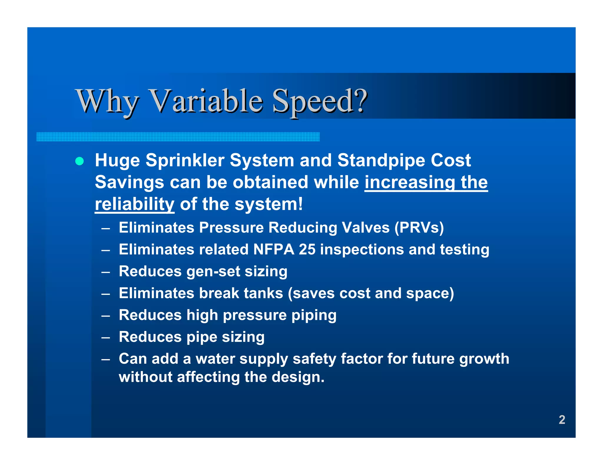
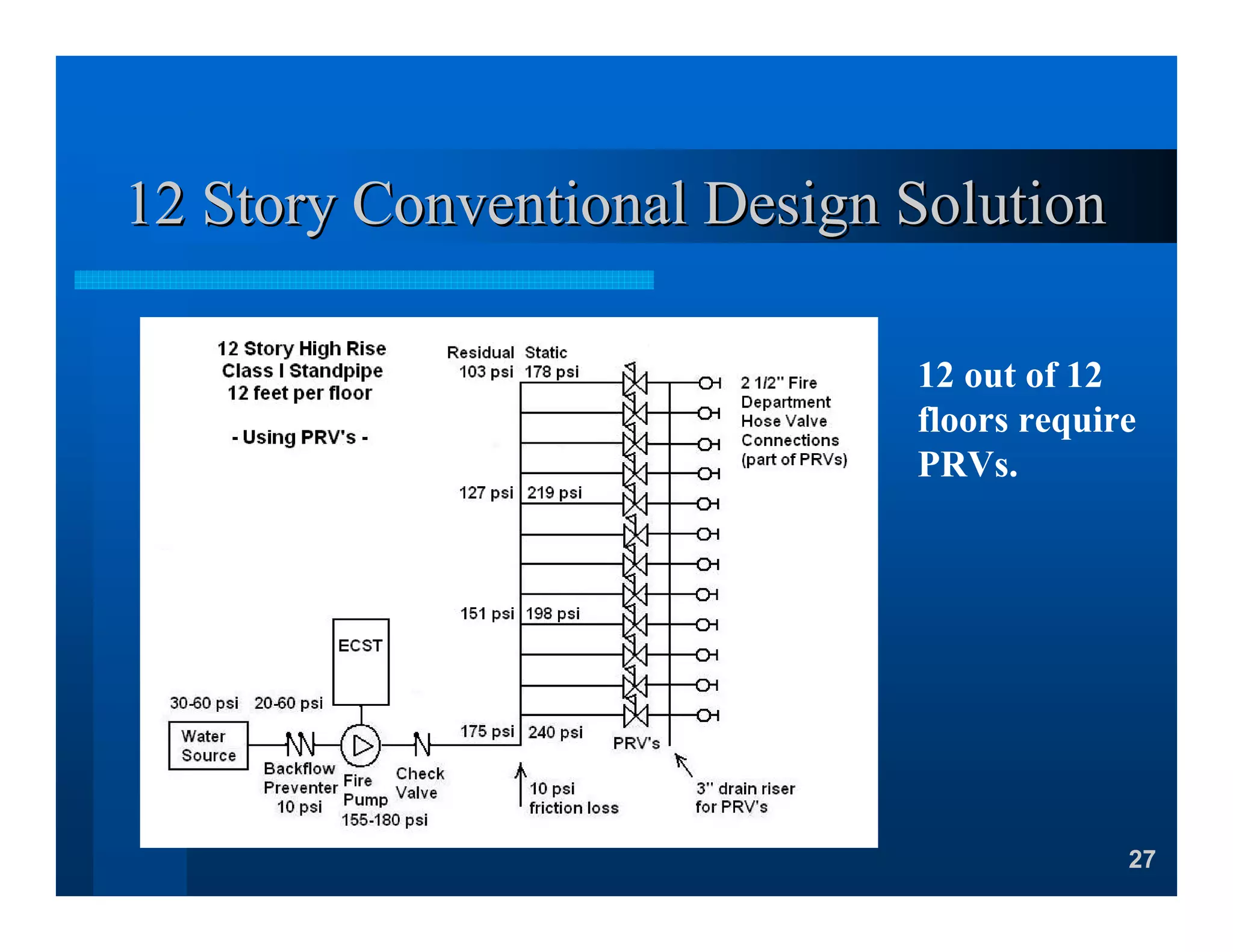
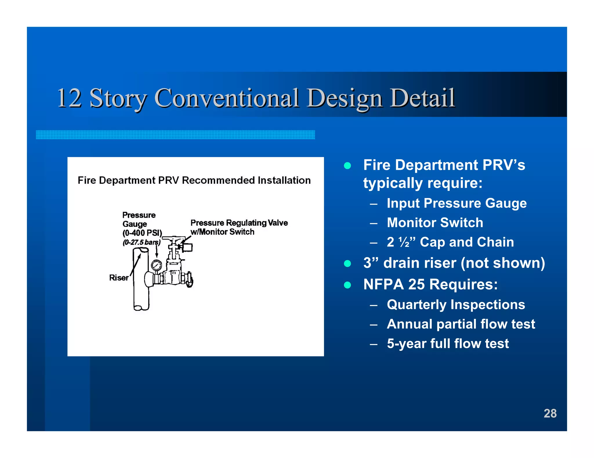
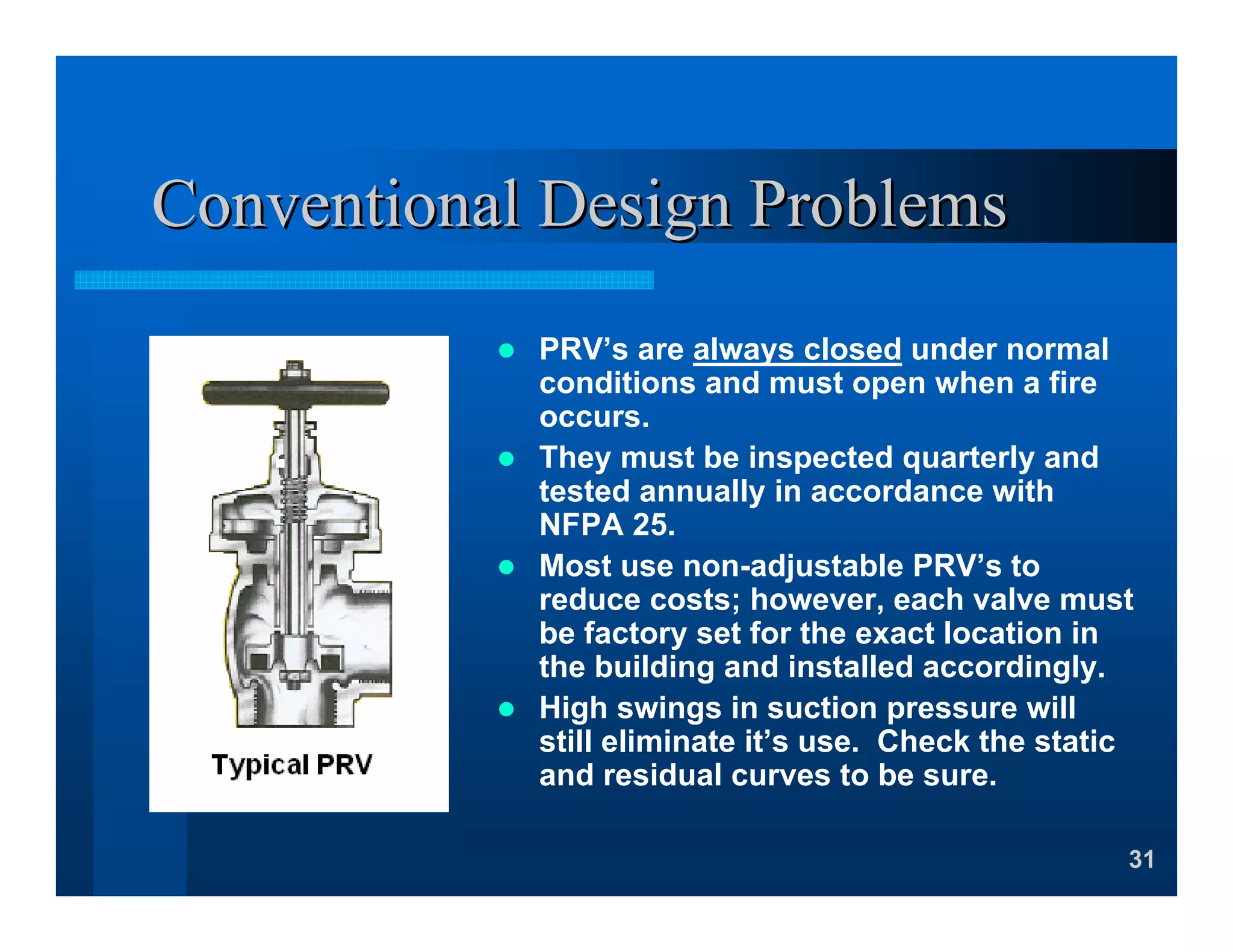
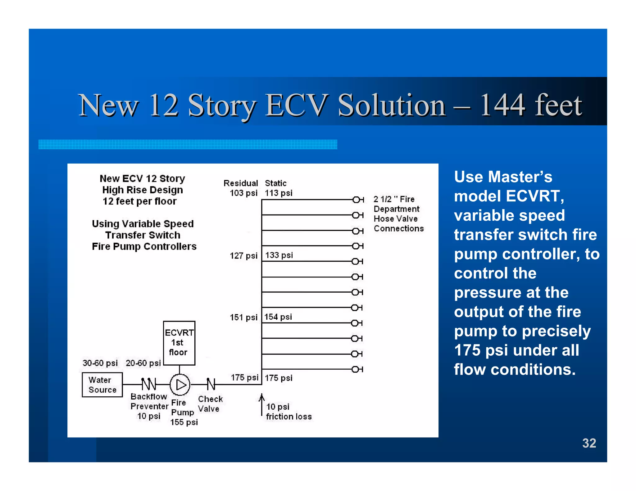
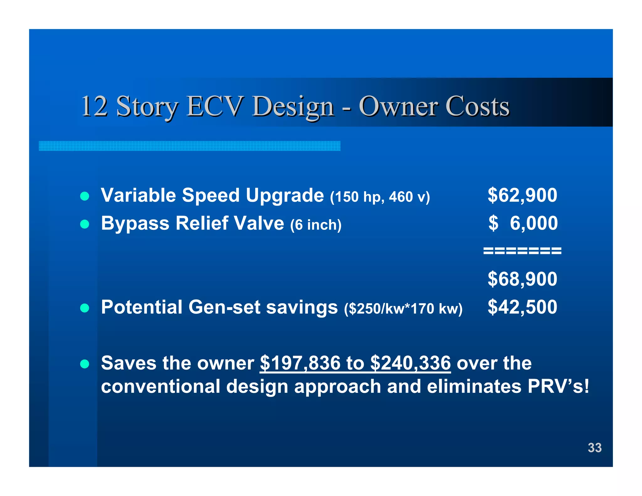
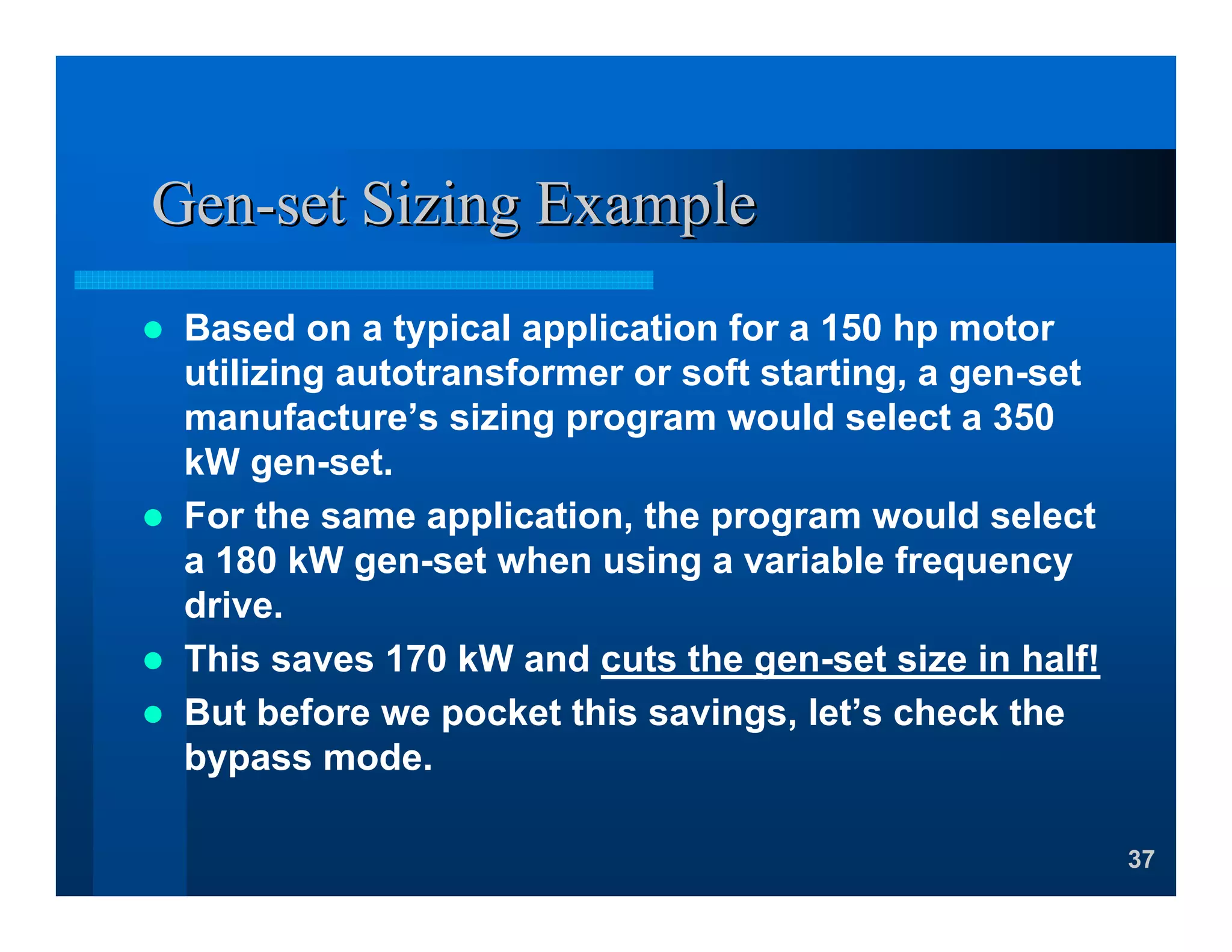
1
Master Control Systems, Inc.Master Control Systems, Inc.
Variable SpeedVariable Speed
Fire Pump ControllersFire Pump Controllers
Listed to NFPA 20Listed to NFPA 20 –– 20032003
2
Why Variable Speed?Why Variable Speed?
Huge Sprinkler System and Standpipe Cost
Savings can be obtained while increasing the
reliability of the system!
– Eliminates Pressure Reducing Valves (PRVs)
– Eliminates related NFPA 25 inspections and testing
– Reduces gen-set sizing
– Eliminates break tanks (saves cost and space)
– Reduces high pressure piping
– Reduces pipe sizing
– Can add a water supply safety factor for future growth
without affecting the design.
3
Ok, what does it look like?Ok, what does it look like?
ModelModel ECVECV--250250--4646--HJKNOYXPN,X47AHJKNOYXPN,X47A Listed For
Fire Protection
4
But is it Reliable? Yes!But is it Reliable? Yes!
Our design is
totally redundant
since the variable
speed drive is
automatically
isolated and
bypassed by the
traditional fire
pump controller
path.
5
Independent Control CircuitIndependent Control Circuit
Further, this is
done with field
proven circuits and
a separate pressure
switch which is
independent of the
variable speed
drive pressure
transducer.
6
Load and Line VFD IsolationLoad and Line VFD Isolation
Load isolation is
added to disconnect
the motor from the
VFD before
connecting it to the
traditional fire pump
controller.
Line isolation is
added to protect the
VFD from service
entrance line
transients.
Load Bypass Line
7
5% Line Reactance for VFD5% Line Reactance for VFD
Reduces effects of line
transients
Reduces electrical line
noise
Reduces RMS line
currents
8
VFD Line Side FusingVFD Line Side Fusing
Fusing is added in the VFD
power path to protect the
traditional fire pump
controller circuit breaker
from tripping due to a fault in
the VFD power path.
This fusing is bypassed in
the traditional fire pump
controller power path.
9
So How Does it Operate?So How Does it Operate?
The controller is started by the pressure switch, just like with
an ordinary fire pump controller.
Once the pressure switch is tripped, the VFD powers up and
begins regulating the motor speed to maintain the set
pressure.
If the system pressure is not high enough to reset the
pressure switch within 20s, the VFD is bypassed.
If the system pressure drops below the trip pressure while
running for more than 20s, the VFD is bypassed.
Once bypassed, the controller will continue running in the
bypass mode until manually reset.
10
Question and AnswersQuestion and Answers
11
LetLet’’s look at the engineering principless look at the engineering principles
By changing the speed of
the pump, the output
pressure can be raised or
lowered accordingly to
maintain a constant system
pressure.
For a centrifugal pump, the
pressure varies by the
square of the speed. For
Example, if a pump
produces 100 psi at rated
speed, it will produce 64 psi
at 80% speed.
Fire Pump Curve
Various Pump Speeds
0
20
40
60
80
100
120
140
160
0 500 1000 1500 2000
Flow - GPM
Pressure-PSI
100% Speed 90% Speed 80% Speed
12
LetLet’’s look at the engineering principless look at the engineering principles
The water supply curve
(blue) and the fire pump
curve (red) add together
to make the system
supply curve (yellow).
As you can see, the
pressure on the system
under low flow conditions
far exceeds the standard
175 psi ratings of most
components.
Fire Pump & Water Supply Curves
0
50
100
150
200
250
0 500 1000 1500 2000
Flow - GPM
Pressure-PSI
System Curve Fire Pump Water Supply
13
LetLet’’s look at the engineering principless look at the engineering principles
With a variable speed
driver, a family of
system curves are
generated. One for
every speed.
Thus you can pick
virtually any pressure
at any speed under the
100% speed system
curve.
System Curve
Various Pump Speeds
0
50
100
150
200
250
0 500 1000 1500 2000
Flow - GPM
Pressure-PSI
100% Speed 90% Speed 80% Speed
14
LetLet’’s look at the engineering principless look at the engineering principles
So by controlling the
speed you can regulate
the pressure to any
value under the 100%
speed system curve,
regardless of flow.
Thus, the design point
can be very close to the
maximum system
pressure allowed (less
friction losses).
System Curve
Variable Speed Drive
0
50
100
150
200
250
0 500 1000 1500 2000
Flow - GPM
Pressure-PSI
System Curve Variable Speed
15
High Rise BuildingsHigh Rise Buildings
If your building is over 75’
tall it’s classified as a
High Rise building by
NFPA 14.
Most jurisdictions will
require a class 1
standpipe system and an
automatic sprinkler
system.
16
Standpipe SystemStandpipe System
The class 1 standpipe system requires a minimum of 100 psi
at the Fire Department hose valve connection on the roof
and a maximum pressure of 175 psi at any hose valve
connection provided.
Before the advent of variable speed controllers, the building
height or zone that could be attained without using PRVs
was about 81 feet.
175 psi under any conditions
– 100 psi FD requirement
– 5 psi additional pressure for friction loss (0.067 psi/ft)
– 10 psi water source variation (30 psi residual)
– 10 psi additional pressure for backflow preventer loss
– 15 psi pump no-flow additional pressure (105 psi x 15%)
=====
35 psi x 2.31 ft/psi = 81 feet.
17
Standpipe SystemStandpipe System
Now with the variable speed controller, you can
raise the maximum height or zone to 150 feet
without the use of PRV’s.
175 psi under any conditions
– 100 psi FD requirement
– 10 psi riser friction loss (0.067 psi/ft)
=====
65 psi x 2.31 ft/psi = 150 feet.
Finally a realistic PRV free building!
18
Automatic Sprinkler SystemsAutomatic Sprinkler Systems
When a combined sprinkler
and standpipe system is used,
the sprinkler system is subject
to the same pressure as the
standpipe system.
Before variable speed
controllers, PRV’s were used
to also keep the sprinkler
system pressure to 175 psi or
below so the designer had a
much greater selection of
sprinkler heads.
19
Question and AnswersQuestion and Answers
20
High Rise CalculationsHigh Rise Calculations
Let’s calculate a 12-
story,144 foot, large
footprint, high rise
building with 12 feet
per floor.
It will have:
– 4 stairways
– 2 sprinkler design
areas per floor.
21
High Rise CalculationsHigh Rise Calculations
With 4 stairways, the required gpm will be 500 for the 1st
and 250 for the others. This adds up to a total of 1250
gpm. For a combined system, only 1000 gpm is needed.
Ideally, the pump pressure is based on the elevation of
the building, plus 100 psi on the roof for the Fire
Department connection less the residual pressure of the
water source. However, the friction loss of the standpipe
and the backflow preventer must also be added.
So if the elevation pressure is 63 psi and the residual
pressure is 30 psi, the ideal pump pressure is 133 psi.
However, we need to add 10 psi for the standpipe loss
and 10 psi for the backflow preventer so the nearest
pump size will be 1000 gpm at 155 psi.
22
Residual CalculationsResidual Calculations –– 144 feet144 feet
23
Static ConditionsStatic Conditions
This looks good so why do we need variable
speed if the maximum pressure is 175 psi?
Because of the high static or low flow fire
conditions.
– Static water source higher
– No drop in backflow preventer
– Pump running at shutoff is higher
– No friction loss in pipes
24
Static OverpressureStatic Overpressure
In this case, the pump adds
25 psi at shutoff.
Note: The max shutoff pressure
per NFPA-20 is 140% which could
add add as much as 62 psi.
The city supply adds 30 psi
from residual to static.
The backflow preventer adds
10 psi from residual to static.
Adding these to the residual
design pressure of 175 will
produce a total static system
pressure of 240 psi.
25
Static CalculationsStatic Calculations –– 144 feet144 feet
Pressures are
too high for 12
out of the 12
floors.
26
12 Story Conventional Design Solution12 Story Conventional Design Solution
Add PRV’s, Pressure Regulating Valves, high
pressure fittings, and drain risers from the 12th floor
down. This amounts to:
– 48 Fire Department PRV’s (12 per stairway x 4)
– 4 Three inch drain risers (1 per stairway)
– 24 Floor Control PRV’s (1 per sprinkler design area x 2)
– 24 Relief valves and piping for the sprinkler PRV’s
27
12 Story Conventional Design Solution12 Story Conventional Design Solution
12 out of 12
floors require
PRVs.
28
12 Story Conventional Design Detail12 Story Conventional Design Detail
Fire Department PRV’s
typically require:
– Input Pressure Gauge
– Monitor Switch
– 2 ½” Cap and Chain
3” drain riser (not shown)
NFPA 25 Requires:
– Quarterly Inspections
– Annual partial flow test
– 5-year full flow test
29
12 Story Conventional Design Detail12 Story Conventional Design Detail
Sprinkler PRV’s typically
require:
– Input Pressure Gauge
– Output Pressure Gauge
– Small relief valve
– Flow switch
– Tamper switch
– Connection to 3 inch
drain riser (not shown)
NFPA 25 Requires:
– Quarterly Inspections
– Annual partial flow test
– 5-year full flow test
30
12 Story Conventional Design12 Story Conventional Design -- Owner CostsOwner Costs
PRV’s, labor and related costs $63,696
($857 /FD PRV x 48, $940/ FC PRV & Accy’s x 24)
3” Drain risers (2 x $30/ft x 144 + 2 x $15/ft x 144) $12,960
NFPA 25 costs for life of building (20 years)
Qtrly Inspect (3 x 24 x .25hr x $100/hr x 20) $36,000
Annual Test (72 x .5hr x $100/hr x 16) $57,600
5-Year Full Flow (72 x 1.0hr x $100 x 4) $28,800
PRV repair costs (72 x 5% x $940 x 20) $67,680
=========
$266,736
31
Conventional Design ProblemsConventional Design Problems
PRV’s are always closed under normal
conditions and must open when a fire
occurs.
They must be inspected quarterly and
tested annually in accordance with
NFPA 25.
Most use non-adjustable PRV’s to
reduce costs; however, each valve must
be factory set for the exact location in
the building and installed accordingly.
High swings in suction pressure will
still eliminate it’s use. Check the static
and residual curves to be sure.
32
New 12 Story ECV SolutionNew 12 Story ECV Solution –– 144 feet144 feet
Use Master’s
model ECVRT,
variable speed
transfer switch fire
pump controller, to
control the
pressure at the
output of the fire
pump to precisely
175 psi under all
flow conditions.
33
12 Story ECV Design12 Story ECV Design -- Owner CostsOwner Costs
Variable Speed Upgrade (150 hp, 460 v) $62,900
Bypass Relief Valve (6 inch) $ 6,000
=======
$68,900
Potential Gen-set savings ($250/kw*170 kw) $42,500
Saves the owner $197,836 to $240,336 over the
conventional design approach and eliminates PRV’s!
34
Variable Speed Application GuidelinesVariable Speed Application Guidelines
The motor should meet the
NEMA design B, code G
requirements and be suitable for
inverter duty applications.
The maximum pump
horsepower should not exceed
the motor nameplate
horsepower. The service factor
should not be used.
A bypass relief valve is required
to handle system overpressures
that may occur when the manual
operator is used or the VFD is
bypassed.
35
GenGen--Set sizingSet sizing
Variable Frequency Drives
with 5% input line
reactance provides the
best form of motor
starting for the gen-set.
The starting current drawn
by the VFD is typically set
to 125% of the motor FLA.
36
More about the GenMore about the Gen--SetSet
Because the variable speed controller starts at
low frequencies, the rated full load torque of
the motor can always be supplied. This always
allows the motor to accelerate to full speed,
unlike wye-delta starting.
NFPA 20 requires that the voltage drop shall
not exceed 15% during starting or 5% during
running. This typically requires the gen-set to
be 2-3 times larger than normal.
Since the VFD is typically set to 125% of motor
FLA, the gen-set may be smaller.
37
GenGen--set Sizing Exampleset Sizing Example
Based on a typical application for a 150 hp motor
utilizing autotransformer or soft starting, a gen-set
manufacture’s sizing program would select a 350
kW gen-set.
For the same application, the program would select
a 180 kW gen-set when using a variable frequency
drive.
This saves 170 kW and cuts the gen-set size in half!
But before we pocket this savings, let’s check the
bypass mode.
38
The GenThe Gen--set and the Bypass modeset and the Bypass mode
As standard, the bypass mode uses full voltage
starting. This may be fine for large gen-sets.
For tightly sized gen-sets, reduced voltage
primary reactor starting is available in the bypass
mode.
Further, all Master EFPC are tested for a 35%
voltage drop even though NFPA 20 only requires
a 15% drop.
39
Question and AnswersQuestion and Answers
40
45 Story High Rise Building45 Story High Rise Building –– 450 feet450 feet
Now let’s calculate a 45
story, small footprint, high
rise building with 10 feet
per floor.
It will have:
– 2 stairways
– 1 sprinkler design areas
per floor.
41
45 Story Conventional Design Solution45 Story Conventional Design Solution
45 out of 45 floors
require PRV’s
Requires 2 separate
electrical risers in 2
inches of concrete
for 22 stories
NFPA 14 requires a
separate pump for
each zone.
NFPA 14 requires
that the maximum
zone pressure not
exceed 350 psi
42
45 Story Conventional Design45 Story Conventional Design -- Owner CostsOwner Costs
PRV’s, labor and related costs $119,430
($857 /FD PRV x 90, $940/ FC PRV & Accy’s x 45)
3” Drain risers (1 x $30/ft x 450 + 1 x $15 x 450) $20,250
NFPA 25 costs for life of building (20 years)
Qtrly Inspect (3 x 45 x .25hr x $100/hr x 20) $67,500
Annual Test (135 x .5hr x $100/hr x 16) $108,000
5-Year Full Flow (135 x 1.0hr x $100 x 4) $54,000
PRV repair costs (135 x 5% x $940 x 20) $126,900
Electrical Riser costs ($200/ft x 300ft x 2) $120,000
=========
$616,080
43
New 45 Story ECV SolutionNew 45 Story ECV Solution –– 450 feet450 feet
Use Master’s model
ECVRT, variable
speed transfer switch
fire pump controller,
to control the
pressure at the output
of the fire pump under
and conditions of
Flow to precisely:
Zone 1 - 175 psi
Zone 2 - 240 psi
Zone 3 - 325 psi
44
45 Story ECV Design45 Story ECV Design -- Owner CostsOwner Costs
Additional Zone $60,000
Variable Speed Upgrade $166,750
(2-150 hp, 1-75 hp, 460 v)
Bypass Relief Valve (3 - 6 inch) $ 18,000
=======
$244,750
Saves the owner $371,330 over the conventional
design approach and eliminates PRV’s!
Note: Series pumping may not reduce the gen-set size
45
The Variable Speed AdvantageThe Variable Speed Advantage
Creates a PRV free building.
Eliminates quarterly inspection and
annual testing of PRVs as required
by NFPA 25.
Reduces the gen-set size.
Eliminates a break tank.
Eliminates the drain riser required
by NFPA 14.
Requires fewer high pressure
fittings, if any.
Allows smaller pipe sizes.
And the best part of all, you have a
redundant, more reliable system for
better fire protection and life safety!
46
Master Control Systems, Inc.Master Control Systems, Inc.
Thank you!Thank you!
And remember, thereAnd remember, there isis aa
differencedifference……
11--800800--462462--74577457
MASTER,MASTER, The intelligent choiceThe intelligent choice

Fire pump controllers

  • 1.
    1 Master Control Systems,Inc.Master Control Systems, Inc. Variable SpeedVariable Speed Fire Pump ControllersFire Pump Controllers Listed to NFPA 20Listed to NFPA 20 –– 20032003
  • 2.
    2 Why Variable Speed?WhyVariable Speed? Huge Sprinkler System and Standpipe Cost Savings can be obtained while increasing the reliability of the system! – Eliminates Pressure Reducing Valves (PRVs) – Eliminates related NFPA 25 inspections and testing – Reduces gen-set sizing – Eliminates break tanks (saves cost and space) – Reduces high pressure piping – Reduces pipe sizing – Can add a water supply safety factor for future growth without affecting the design.
  • 3.
    3 Ok, what doesit look like?Ok, what does it look like? ModelModel ECVECV--250250--4646--HJKNOYXPN,X47AHJKNOYXPN,X47A Listed For Fire Protection
  • 4.
    4 But is itReliable? Yes!But is it Reliable? Yes! Our design is totally redundant since the variable speed drive is automatically isolated and bypassed by the traditional fire pump controller path.
  • 5.
    5 Independent Control CircuitIndependentControl Circuit Further, this is done with field proven circuits and a separate pressure switch which is independent of the variable speed drive pressure transducer.
  • 6.
    6 Load and LineVFD IsolationLoad and Line VFD Isolation Load isolation is added to disconnect the motor from the VFD before connecting it to the traditional fire pump controller. Line isolation is added to protect the VFD from service entrance line transients. Load Bypass Line
  • 7.
    7 5% Line Reactancefor VFD5% Line Reactance for VFD Reduces effects of line transients Reduces electrical line noise Reduces RMS line currents
  • 8.
    8 VFD Line SideFusingVFD Line Side Fusing Fusing is added in the VFD power path to protect the traditional fire pump controller circuit breaker from tripping due to a fault in the VFD power path. This fusing is bypassed in the traditional fire pump controller power path.
  • 9.
    9 So How Doesit Operate?So How Does it Operate? The controller is started by the pressure switch, just like with an ordinary fire pump controller. Once the pressure switch is tripped, the VFD powers up and begins regulating the motor speed to maintain the set pressure. If the system pressure is not high enough to reset the pressure switch within 20s, the VFD is bypassed. If the system pressure drops below the trip pressure while running for more than 20s, the VFD is bypassed. Once bypassed, the controller will continue running in the bypass mode until manually reset.
  • 10.
  • 11.
    11 LetLet’’s look atthe engineering principless look at the engineering principles By changing the speed of the pump, the output pressure can be raised or lowered accordingly to maintain a constant system pressure. For a centrifugal pump, the pressure varies by the square of the speed. For Example, if a pump produces 100 psi at rated speed, it will produce 64 psi at 80% speed. Fire Pump Curve Various Pump Speeds 0 20 40 60 80 100 120 140 160 0 500 1000 1500 2000 Flow - GPM Pressure-PSI 100% Speed 90% Speed 80% Speed
  • 12.
    12 LetLet’’s look atthe engineering principless look at the engineering principles The water supply curve (blue) and the fire pump curve (red) add together to make the system supply curve (yellow). As you can see, the pressure on the system under low flow conditions far exceeds the standard 175 psi ratings of most components. Fire Pump & Water Supply Curves 0 50 100 150 200 250 0 500 1000 1500 2000 Flow - GPM Pressure-PSI System Curve Fire Pump Water Supply
  • 13.
    13 LetLet’’s look atthe engineering principless look at the engineering principles With a variable speed driver, a family of system curves are generated. One for every speed. Thus you can pick virtually any pressure at any speed under the 100% speed system curve. System Curve Various Pump Speeds 0 50 100 150 200 250 0 500 1000 1500 2000 Flow - GPM Pressure-PSI 100% Speed 90% Speed 80% Speed
  • 14.
    14 LetLet’’s look atthe engineering principless look at the engineering principles So by controlling the speed you can regulate the pressure to any value under the 100% speed system curve, regardless of flow. Thus, the design point can be very close to the maximum system pressure allowed (less friction losses). System Curve Variable Speed Drive 0 50 100 150 200 250 0 500 1000 1500 2000 Flow - GPM Pressure-PSI System Curve Variable Speed
  • 15.
    15 High Rise BuildingsHighRise Buildings If your building is over 75’ tall it’s classified as a High Rise building by NFPA 14. Most jurisdictions will require a class 1 standpipe system and an automatic sprinkler system.
  • 16.
    16 Standpipe SystemStandpipe System Theclass 1 standpipe system requires a minimum of 100 psi at the Fire Department hose valve connection on the roof and a maximum pressure of 175 psi at any hose valve connection provided. Before the advent of variable speed controllers, the building height or zone that could be attained without using PRVs was about 81 feet. 175 psi under any conditions – 100 psi FD requirement – 5 psi additional pressure for friction loss (0.067 psi/ft) – 10 psi water source variation (30 psi residual) – 10 psi additional pressure for backflow preventer loss – 15 psi pump no-flow additional pressure (105 psi x 15%) ===== 35 psi x 2.31 ft/psi = 81 feet.
  • 17.
    17 Standpipe SystemStandpipe System Nowwith the variable speed controller, you can raise the maximum height or zone to 150 feet without the use of PRV’s. 175 psi under any conditions – 100 psi FD requirement – 10 psi riser friction loss (0.067 psi/ft) ===== 65 psi x 2.31 ft/psi = 150 feet. Finally a realistic PRV free building!
  • 18.
    18 Automatic Sprinkler SystemsAutomaticSprinkler Systems When a combined sprinkler and standpipe system is used, the sprinkler system is subject to the same pressure as the standpipe system. Before variable speed controllers, PRV’s were used to also keep the sprinkler system pressure to 175 psi or below so the designer had a much greater selection of sprinkler heads.
  • 19.
  • 20.
    20 High Rise CalculationsHighRise Calculations Let’s calculate a 12- story,144 foot, large footprint, high rise building with 12 feet per floor. It will have: – 4 stairways – 2 sprinkler design areas per floor.
  • 21.
    21 High Rise CalculationsHighRise Calculations With 4 stairways, the required gpm will be 500 for the 1st and 250 for the others. This adds up to a total of 1250 gpm. For a combined system, only 1000 gpm is needed. Ideally, the pump pressure is based on the elevation of the building, plus 100 psi on the roof for the Fire Department connection less the residual pressure of the water source. However, the friction loss of the standpipe and the backflow preventer must also be added. So if the elevation pressure is 63 psi and the residual pressure is 30 psi, the ideal pump pressure is 133 psi. However, we need to add 10 psi for the standpipe loss and 10 psi for the backflow preventer so the nearest pump size will be 1000 gpm at 155 psi.
  • 22.
  • 23.
    23 Static ConditionsStatic Conditions Thislooks good so why do we need variable speed if the maximum pressure is 175 psi? Because of the high static or low flow fire conditions. – Static water source higher – No drop in backflow preventer – Pump running at shutoff is higher – No friction loss in pipes
  • 24.
    24 Static OverpressureStatic Overpressure Inthis case, the pump adds 25 psi at shutoff. Note: The max shutoff pressure per NFPA-20 is 140% which could add add as much as 62 psi. The city supply adds 30 psi from residual to static. The backflow preventer adds 10 psi from residual to static. Adding these to the residual design pressure of 175 will produce a total static system pressure of 240 psi.
  • 25.
    25 Static CalculationsStatic Calculations–– 144 feet144 feet Pressures are too high for 12 out of the 12 floors.
  • 26.
    26 12 Story ConventionalDesign Solution12 Story Conventional Design Solution Add PRV’s, Pressure Regulating Valves, high pressure fittings, and drain risers from the 12th floor down. This amounts to: – 48 Fire Department PRV’s (12 per stairway x 4) – 4 Three inch drain risers (1 per stairway) – 24 Floor Control PRV’s (1 per sprinkler design area x 2) – 24 Relief valves and piping for the sprinkler PRV’s
  • 27.
    27 12 Story ConventionalDesign Solution12 Story Conventional Design Solution 12 out of 12 floors require PRVs.
  • 28.
    28 12 Story ConventionalDesign Detail12 Story Conventional Design Detail Fire Department PRV’s typically require: – Input Pressure Gauge – Monitor Switch – 2 ½” Cap and Chain 3” drain riser (not shown) NFPA 25 Requires: – Quarterly Inspections – Annual partial flow test – 5-year full flow test
  • 29.
    29 12 Story ConventionalDesign Detail12 Story Conventional Design Detail Sprinkler PRV’s typically require: – Input Pressure Gauge – Output Pressure Gauge – Small relief valve – Flow switch – Tamper switch – Connection to 3 inch drain riser (not shown) NFPA 25 Requires: – Quarterly Inspections – Annual partial flow test – 5-year full flow test
  • 30.
    30 12 Story ConventionalDesign12 Story Conventional Design -- Owner CostsOwner Costs PRV’s, labor and related costs $63,696 ($857 /FD PRV x 48, $940/ FC PRV & Accy’s x 24) 3” Drain risers (2 x $30/ft x 144 + 2 x $15/ft x 144) $12,960 NFPA 25 costs for life of building (20 years) Qtrly Inspect (3 x 24 x .25hr x $100/hr x 20) $36,000 Annual Test (72 x .5hr x $100/hr x 16) $57,600 5-Year Full Flow (72 x 1.0hr x $100 x 4) $28,800 PRV repair costs (72 x 5% x $940 x 20) $67,680 ========= $266,736
  • 31.
    31 Conventional Design ProblemsConventionalDesign Problems PRV’s are always closed under normal conditions and must open when a fire occurs. They must be inspected quarterly and tested annually in accordance with NFPA 25. Most use non-adjustable PRV’s to reduce costs; however, each valve must be factory set for the exact location in the building and installed accordingly. High swings in suction pressure will still eliminate it’s use. Check the static and residual curves to be sure.
  • 32.
    32 New 12 StoryECV SolutionNew 12 Story ECV Solution –– 144 feet144 feet Use Master’s model ECVRT, variable speed transfer switch fire pump controller, to control the pressure at the output of the fire pump to precisely 175 psi under all flow conditions.
  • 33.
    33 12 Story ECVDesign12 Story ECV Design -- Owner CostsOwner Costs Variable Speed Upgrade (150 hp, 460 v) $62,900 Bypass Relief Valve (6 inch) $ 6,000 ======= $68,900 Potential Gen-set savings ($250/kw*170 kw) $42,500 Saves the owner $197,836 to $240,336 over the conventional design approach and eliminates PRV’s!
  • 34.
    34 Variable Speed ApplicationGuidelinesVariable Speed Application Guidelines The motor should meet the NEMA design B, code G requirements and be suitable for inverter duty applications. The maximum pump horsepower should not exceed the motor nameplate horsepower. The service factor should not be used. A bypass relief valve is required to handle system overpressures that may occur when the manual operator is used or the VFD is bypassed.
  • 35.
    35 GenGen--Set sizingSet sizing VariableFrequency Drives with 5% input line reactance provides the best form of motor starting for the gen-set. The starting current drawn by the VFD is typically set to 125% of the motor FLA.
  • 36.
    36 More about theGenMore about the Gen--SetSet Because the variable speed controller starts at low frequencies, the rated full load torque of the motor can always be supplied. This always allows the motor to accelerate to full speed, unlike wye-delta starting. NFPA 20 requires that the voltage drop shall not exceed 15% during starting or 5% during running. This typically requires the gen-set to be 2-3 times larger than normal. Since the VFD is typically set to 125% of motor FLA, the gen-set may be smaller.
  • 37.
    37 GenGen--set Sizing ExamplesetSizing Example Based on a typical application for a 150 hp motor utilizing autotransformer or soft starting, a gen-set manufacture’s sizing program would select a 350 kW gen-set. For the same application, the program would select a 180 kW gen-set when using a variable frequency drive. This saves 170 kW and cuts the gen-set size in half! But before we pocket this savings, let’s check the bypass mode.
  • 38.
    38 The GenThe Gen--setand the Bypass modeset and the Bypass mode As standard, the bypass mode uses full voltage starting. This may be fine for large gen-sets. For tightly sized gen-sets, reduced voltage primary reactor starting is available in the bypass mode. Further, all Master EFPC are tested for a 35% voltage drop even though NFPA 20 only requires a 15% drop.
  • 39.
  • 40.
    40 45 Story HighRise Building45 Story High Rise Building –– 450 feet450 feet Now let’s calculate a 45 story, small footprint, high rise building with 10 feet per floor. It will have: – 2 stairways – 1 sprinkler design areas per floor.
  • 41.
    41 45 Story ConventionalDesign Solution45 Story Conventional Design Solution 45 out of 45 floors require PRV’s Requires 2 separate electrical risers in 2 inches of concrete for 22 stories NFPA 14 requires a separate pump for each zone. NFPA 14 requires that the maximum zone pressure not exceed 350 psi
  • 42.
    42 45 Story ConventionalDesign45 Story Conventional Design -- Owner CostsOwner Costs PRV’s, labor and related costs $119,430 ($857 /FD PRV x 90, $940/ FC PRV & Accy’s x 45) 3” Drain risers (1 x $30/ft x 450 + 1 x $15 x 450) $20,250 NFPA 25 costs for life of building (20 years) Qtrly Inspect (3 x 45 x .25hr x $100/hr x 20) $67,500 Annual Test (135 x .5hr x $100/hr x 16) $108,000 5-Year Full Flow (135 x 1.0hr x $100 x 4) $54,000 PRV repair costs (135 x 5% x $940 x 20) $126,900 Electrical Riser costs ($200/ft x 300ft x 2) $120,000 ========= $616,080
  • 43.
    43 New 45 StoryECV SolutionNew 45 Story ECV Solution –– 450 feet450 feet Use Master’s model ECVRT, variable speed transfer switch fire pump controller, to control the pressure at the output of the fire pump under and conditions of Flow to precisely: Zone 1 - 175 psi Zone 2 - 240 psi Zone 3 - 325 psi
  • 44.
    44 45 Story ECVDesign45 Story ECV Design -- Owner CostsOwner Costs Additional Zone $60,000 Variable Speed Upgrade $166,750 (2-150 hp, 1-75 hp, 460 v) Bypass Relief Valve (3 - 6 inch) $ 18,000 ======= $244,750 Saves the owner $371,330 over the conventional design approach and eliminates PRV’s! Note: Series pumping may not reduce the gen-set size
  • 45.
    45 The Variable SpeedAdvantageThe Variable Speed Advantage Creates a PRV free building. Eliminates quarterly inspection and annual testing of PRVs as required by NFPA 25. Reduces the gen-set size. Eliminates a break tank. Eliminates the drain riser required by NFPA 14. Requires fewer high pressure fittings, if any. Allows smaller pipe sizes. And the best part of all, you have a redundant, more reliable system for better fire protection and life safety!
  • 46.
    46 Master Control Systems,Inc.Master Control Systems, Inc. Thank you!Thank you! And remember, thereAnd remember, there isis aa differencedifference…… 11--800800--462462--74577457 MASTER,MASTER, The intelligent choiceThe intelligent choice