Downloaded 1,651 times
![1 - Break Tanks 5.30 Break Tanks. Where a break tank is used to provide the pump suction water supply, the installation shall comply with this section. 5.30.1 Application. Break tanks are used for one or more of the following reasons: (1) As a backflow prevention device… [E.g.: City of Houston, Texas] (2) To eliminate pressure fluctuations in the city water supply… (3) To augment the city water supply… 5.30.2 Break Tank Size. The tank shall be sized for a minimum duration of 15 minutes with the fire pump operating at 150 percent of rated capacity. 5.30.3 Refill Mechanism -- on next slides. 5.30.4 The break tank shall be installed in accordance with NFPA 22, Standard for Water Tanks for Private Fire Protection .](https://image.slidesharecdn.com/ddatadirdatanfpa-jsnseminars2009t33firepumpsystempressurecontrol-090421180524-phpapp02/75/Fire-Pump-System-Pressure-Control-3-2048.jpg)
![Break Tanks Refill Requirements - cont'd 5.30.3.2 If the break tank is sized to a min. of 30 minutes of the max. system demand, the refill mechanism must meet 5.30.3.2.1 through 5.30.3.2.5. 5.30.3.2.1 The refill mechanism must supply 110 percent of total fire protection system demand [110% × (Total Demand Tank Capacity) / Duration] 5.30.3.2.2 A manual tank fill bypass must also supply the tank at 110 percent of the total system demand [110% × (Total Demand Tank Capacity) / Duration] 5.30.3.2.3 The pipe between the city connection and the automatic fill valve must be installed per NFPA24, Standard for the Installation of Private Fire Service Mains and Their Appurtenances . 5.30.3.2.4 The automatic filling mechanism must be maintained at a min. temperature of 40°F (4.4°C). 5.30.3.2.5 The automatic filling mechanism must activate a maximum of 6 in. (152 mm) below the overflow level.](https://image.slidesharecdn.com/ddatadirdatanfpa-jsnseminars2009t33firepumpsystempressurecontrol-090421180524-phpapp02/75/Fire-Pump-System-Pressure-Control-5-2048.jpg)
![2 - Pressure Regulating or Reducing Valves Floor Valves - Recognized in NFPA-13 - Some Redundancy (Floor Below and/or Floor Above) - Prohibited in some jurisdictions Riser or Main Valves - Prohibited in NFPA-20 - Clause 5.15.10 " No pressure-regulating devices…" [except for "Low Suction Throttling Valves"] & - Clause 5.7.6.2* Pressure relief valves and pressure regulating devices in the fire pump installation shall not be used as a means to meet the requirements of 5.7.6.1. - Prohibited in NFPA-24 5.3.1 "No pressure-regulating valve…" - Recognized in NFPA-14 -- but: Anecdotal and direct observation of failures: Stick Open or Closed & Destructive Oscillation](https://image.slidesharecdn.com/ddatadirdatanfpa-jsnseminars2009t33firepumpsystempressurecontrol-090421180524-phpapp02/75/Fire-Pump-System-Pressure-Control-6-2048.jpg)


![Questions ? [email_address] 847-677-3468](https://image.slidesharecdn.com/ddatadirdatanfpa-jsnseminars2009t33firepumpsystempressurecontrol-090421180524-phpapp02/75/Fire-Pump-System-Pressure-Control-78-2048.jpg)

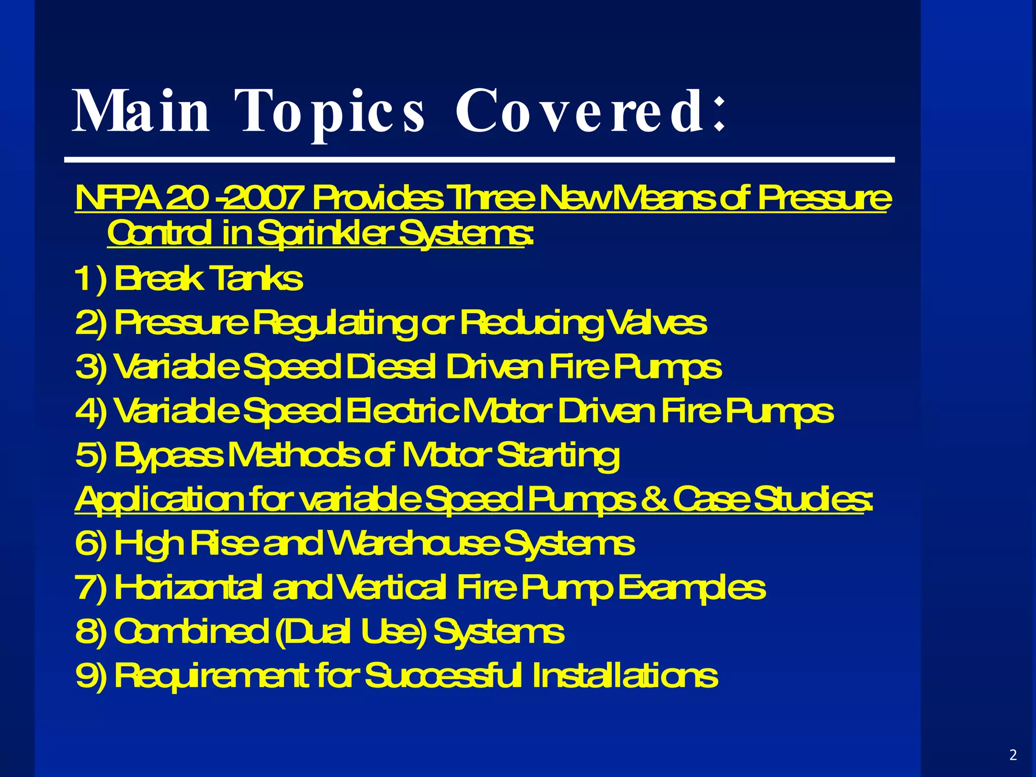
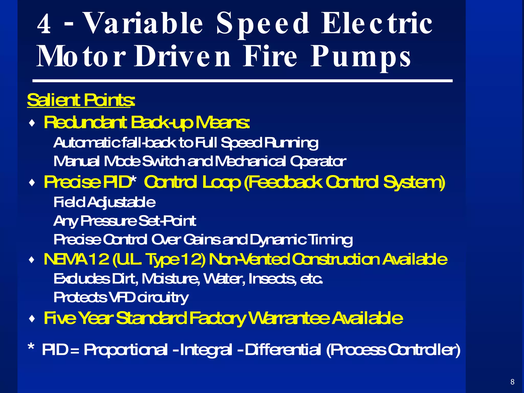
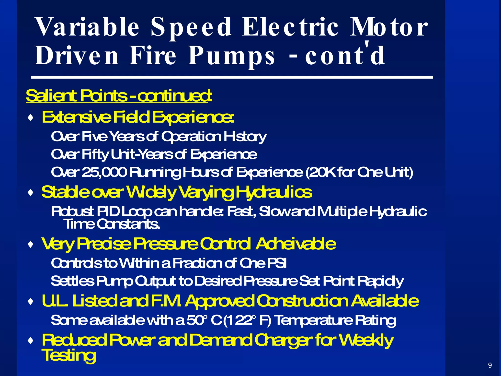
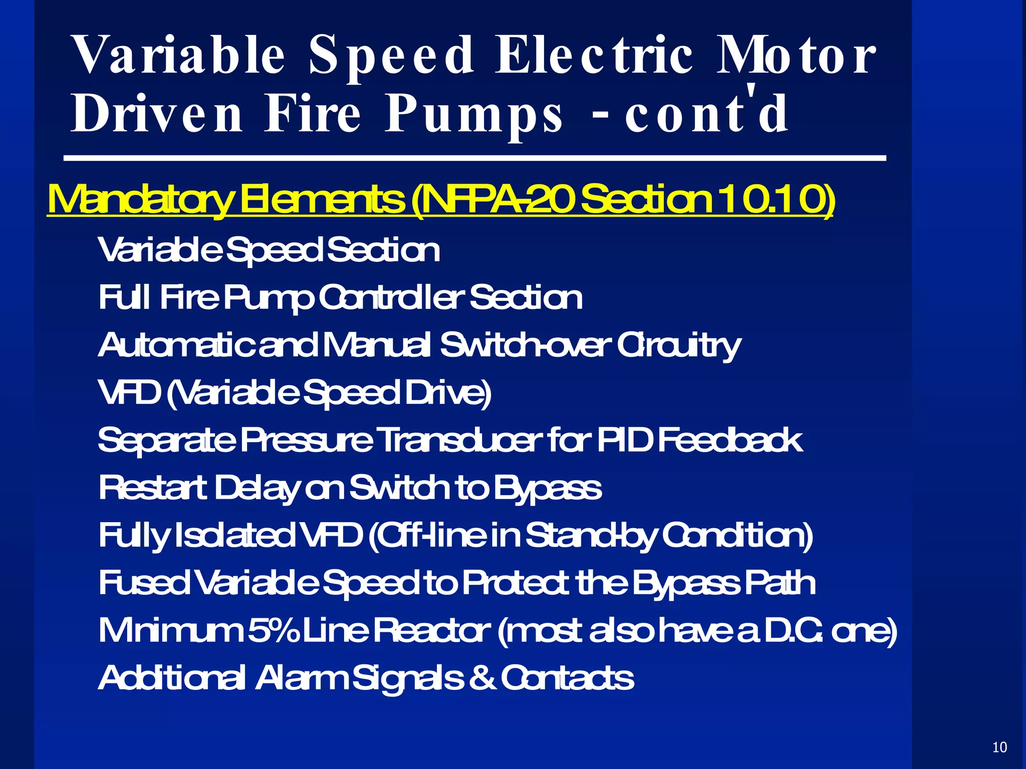
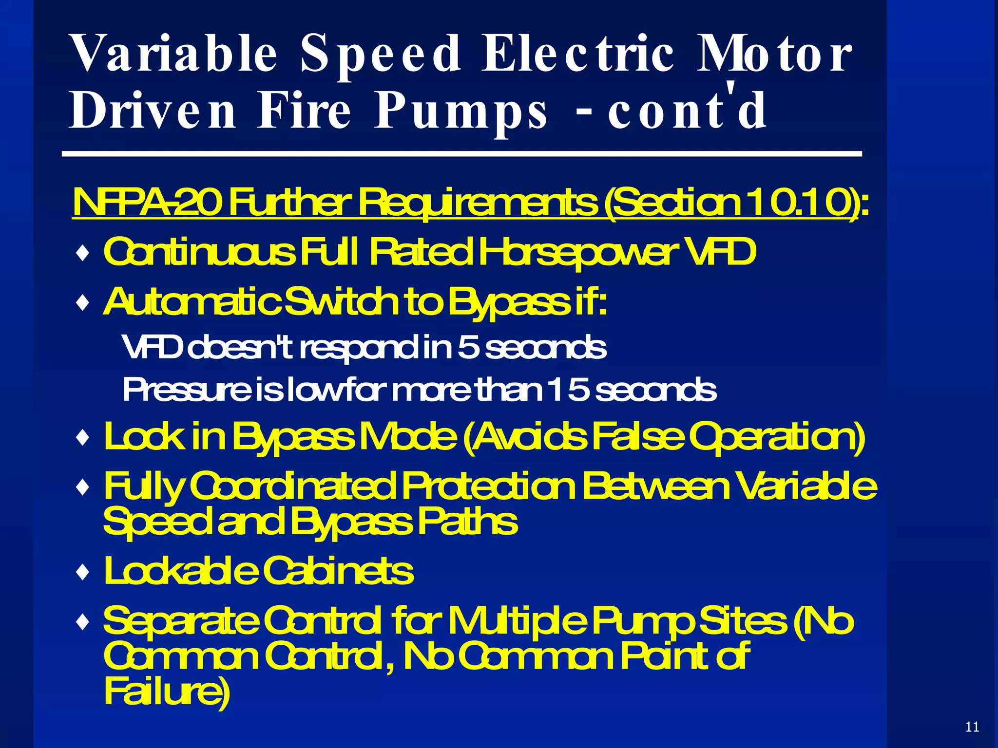
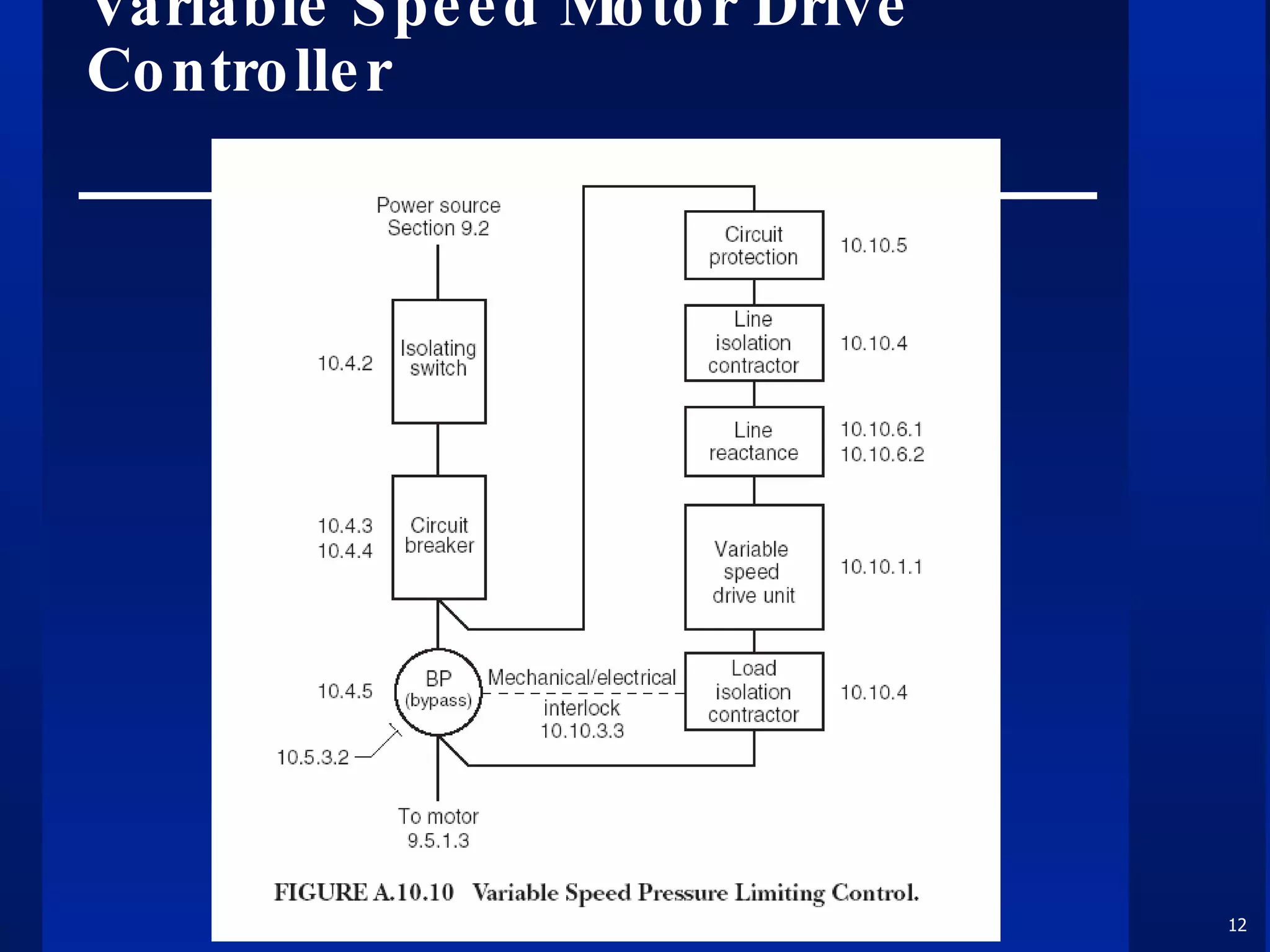
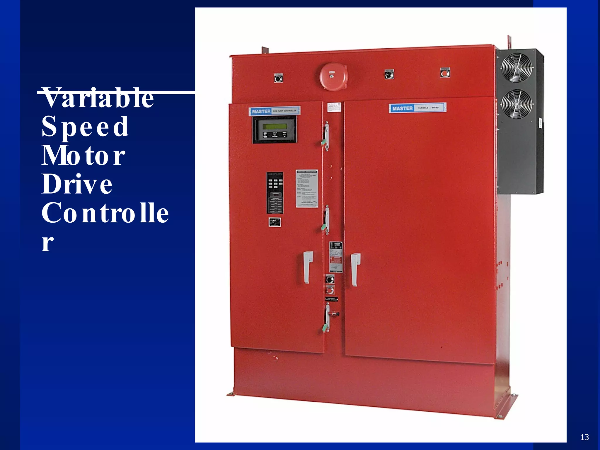
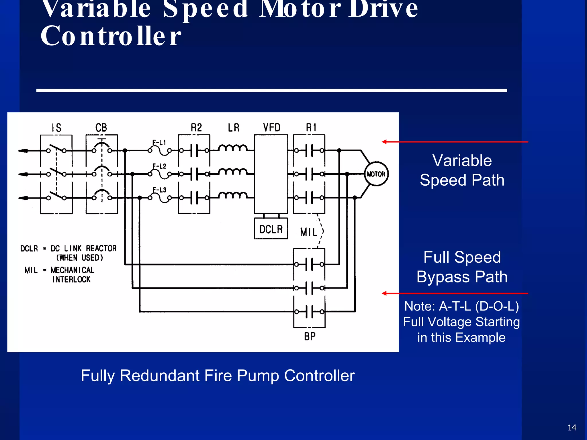
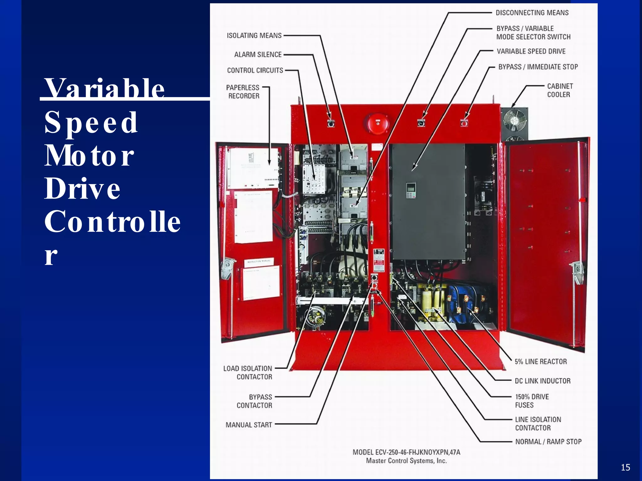
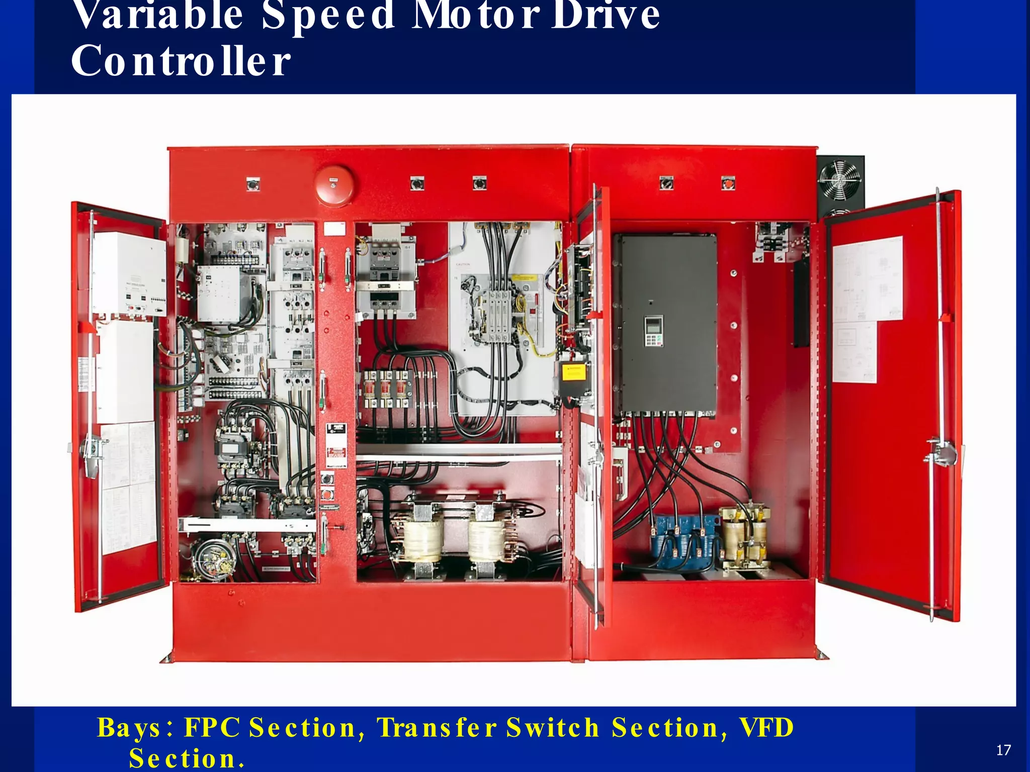
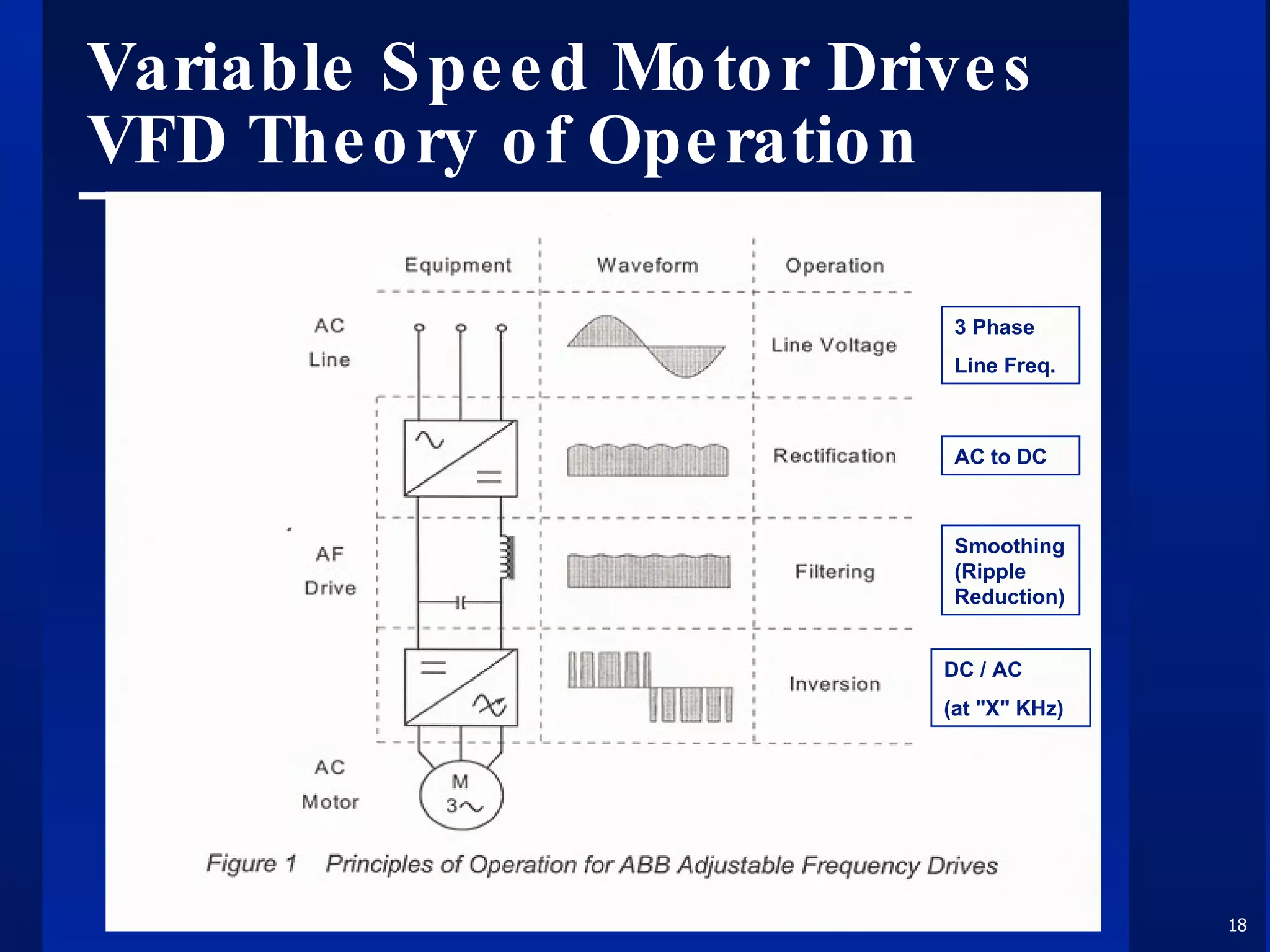
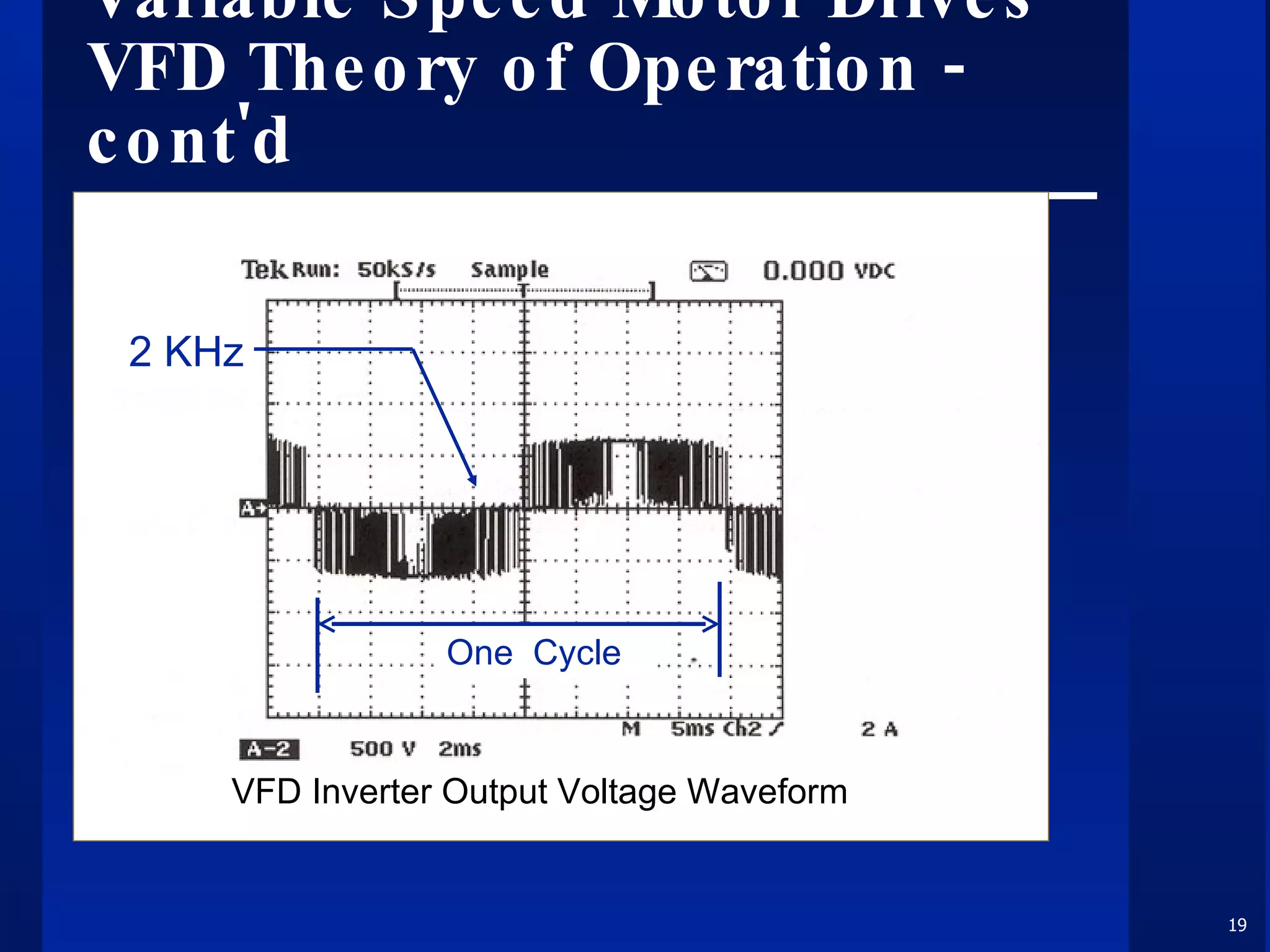
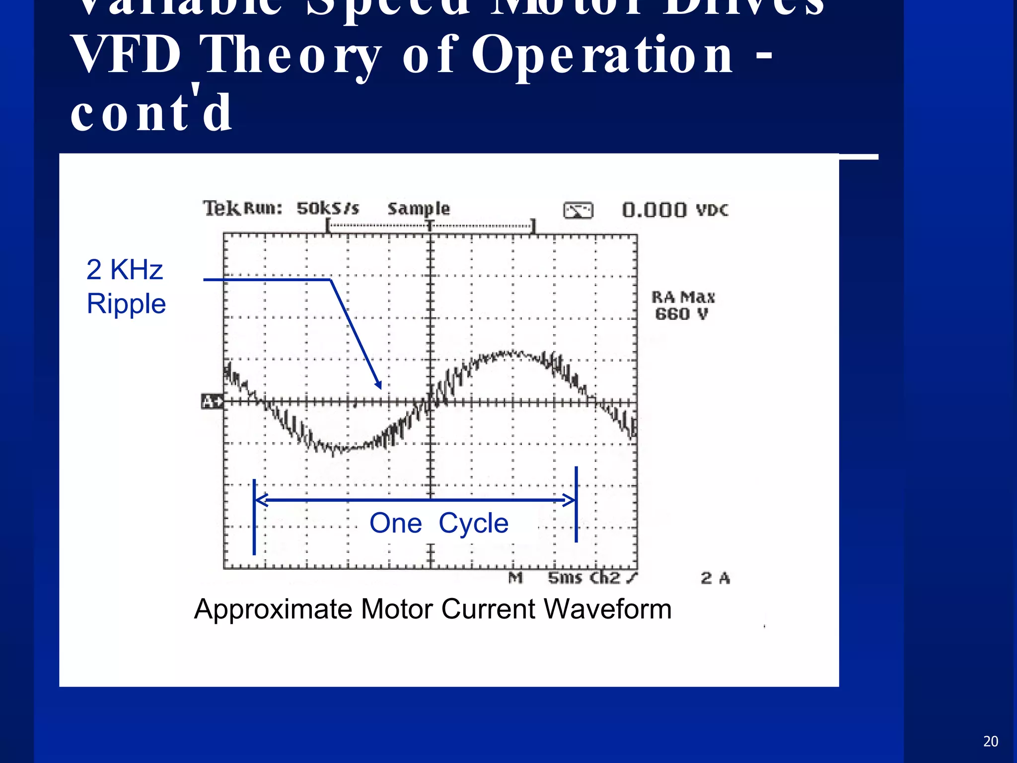
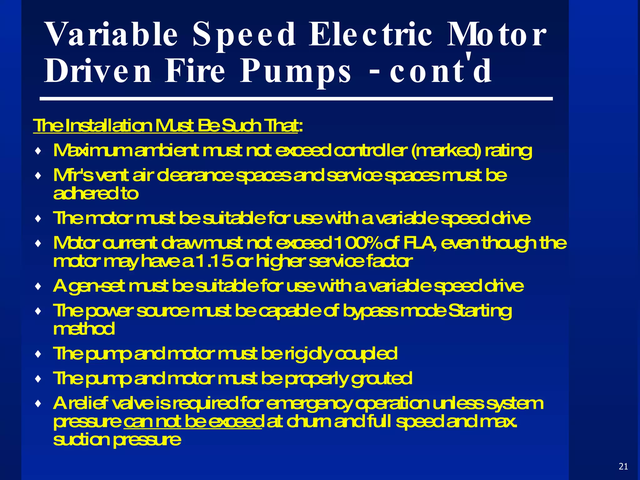
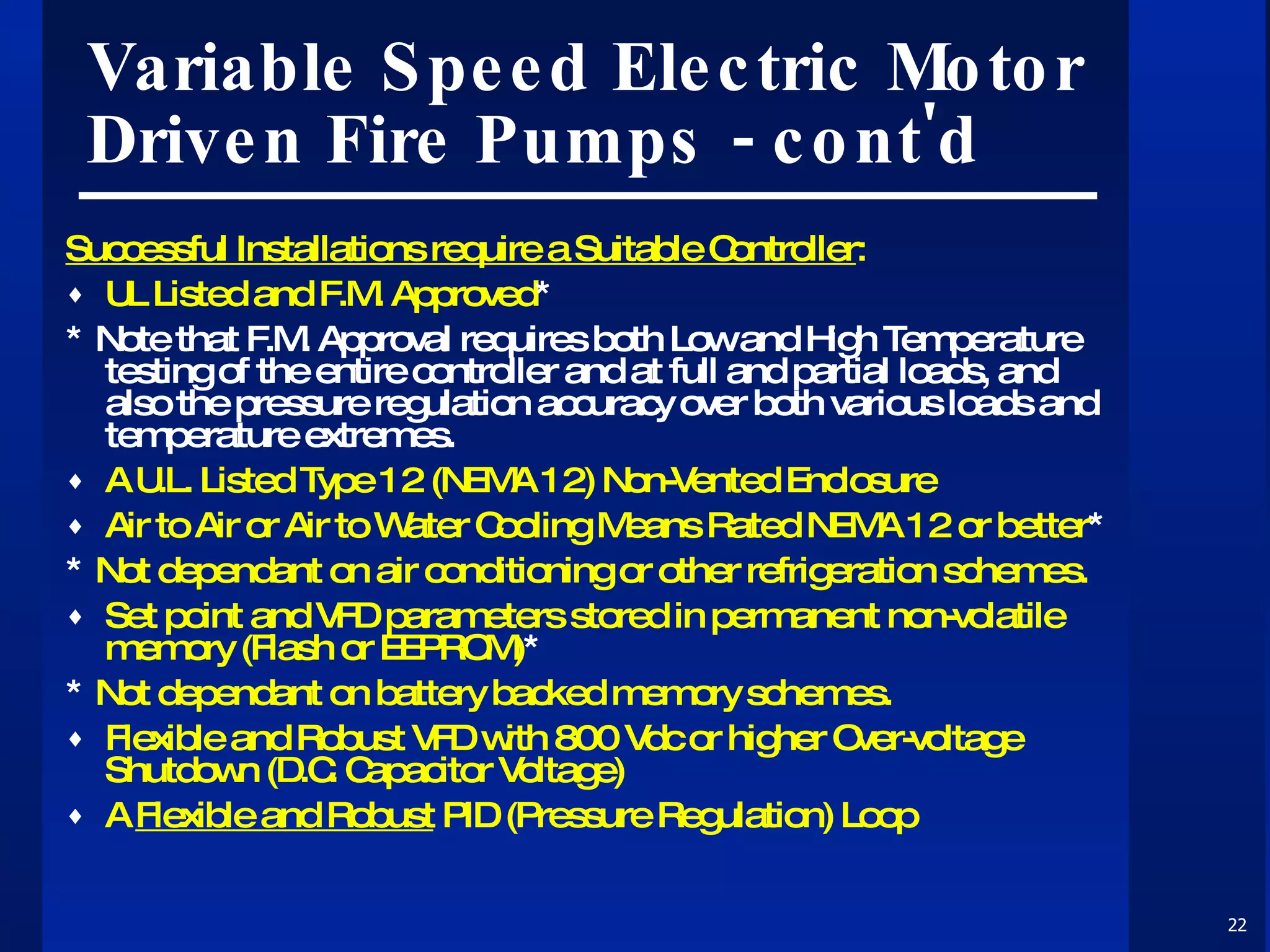
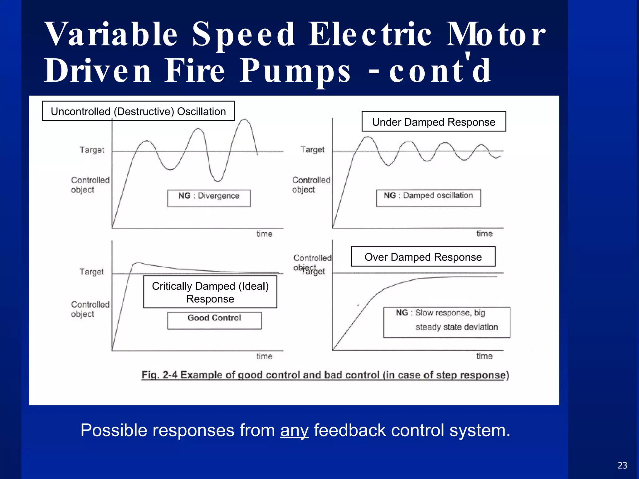
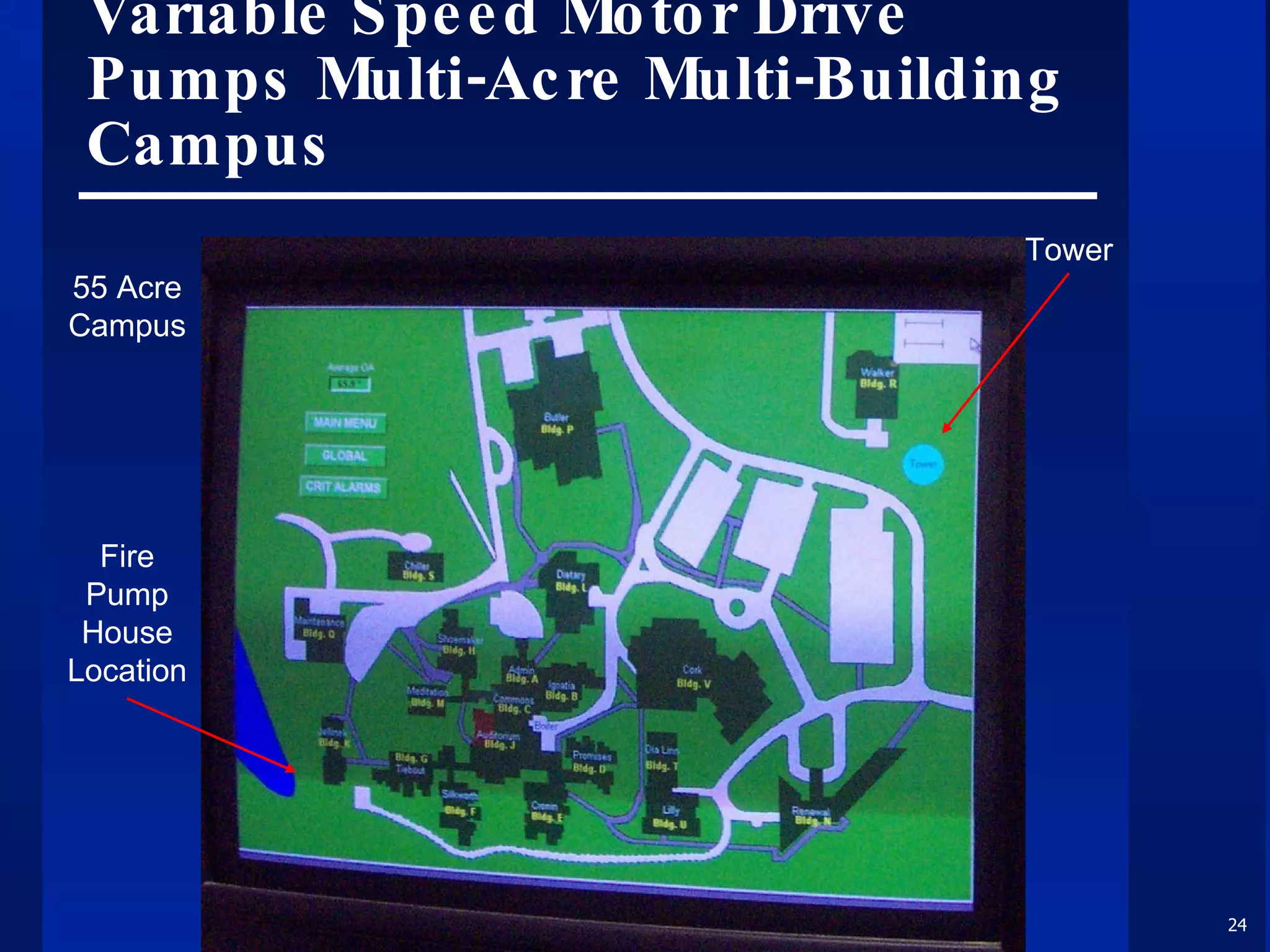
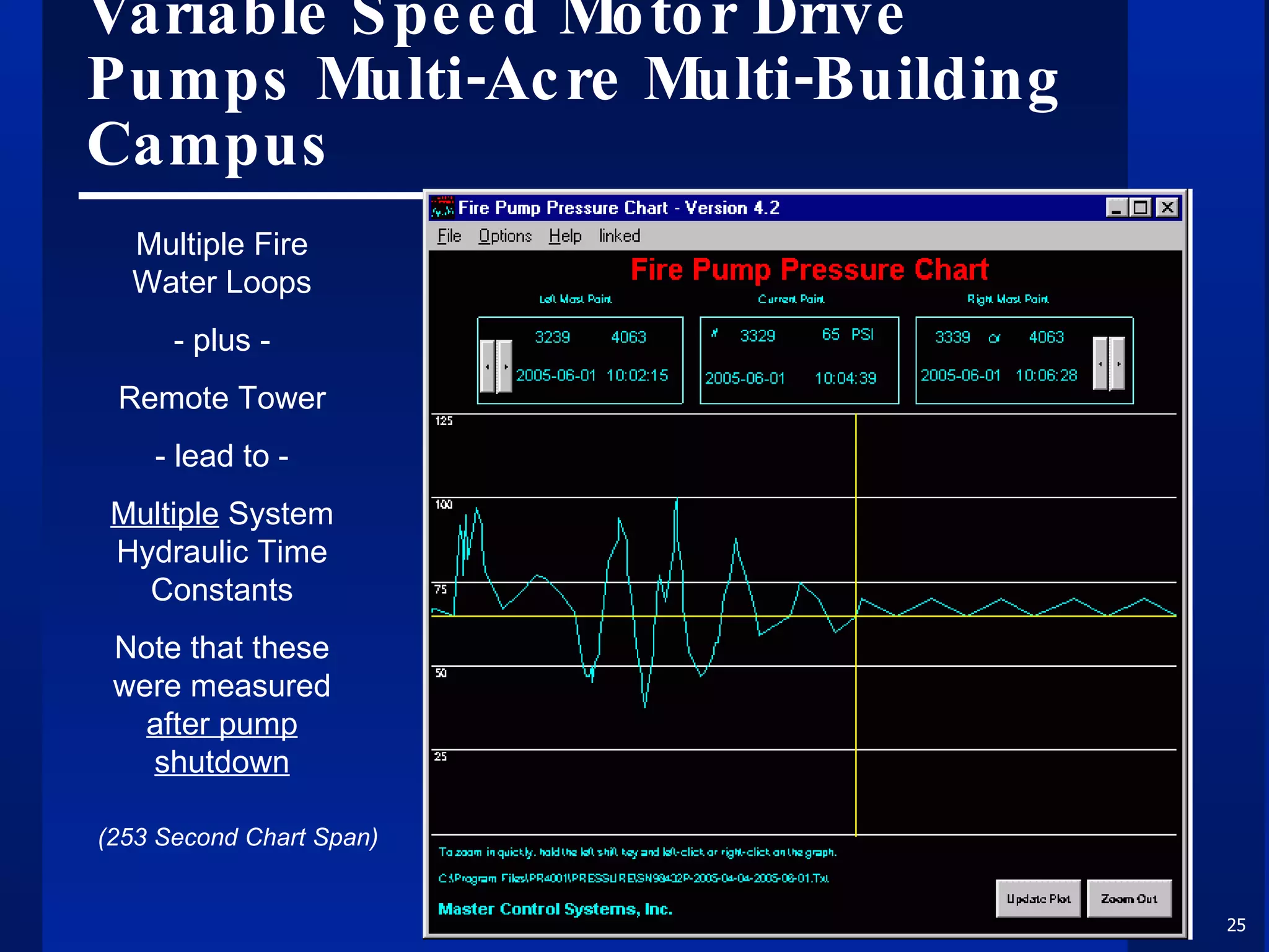
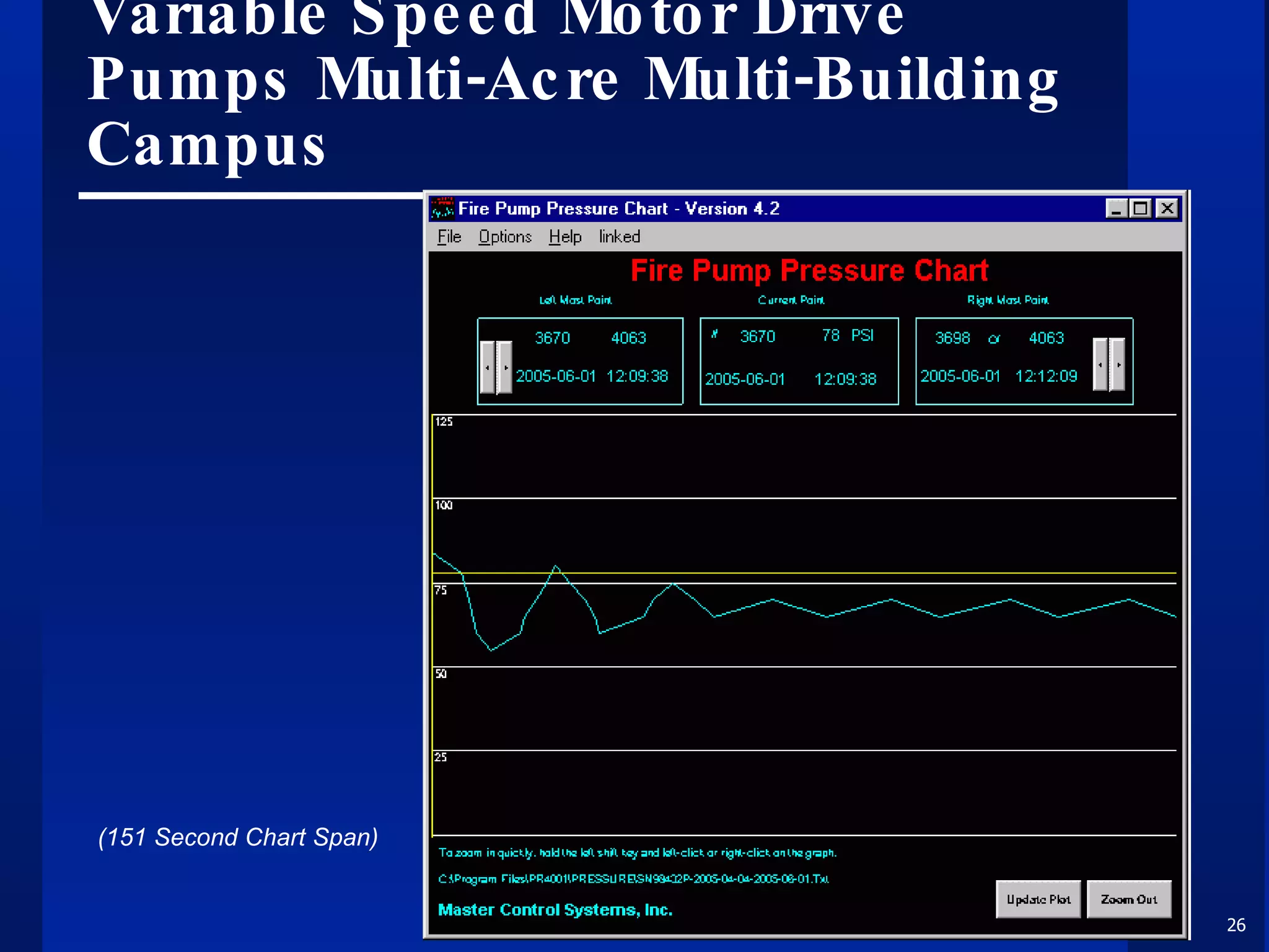
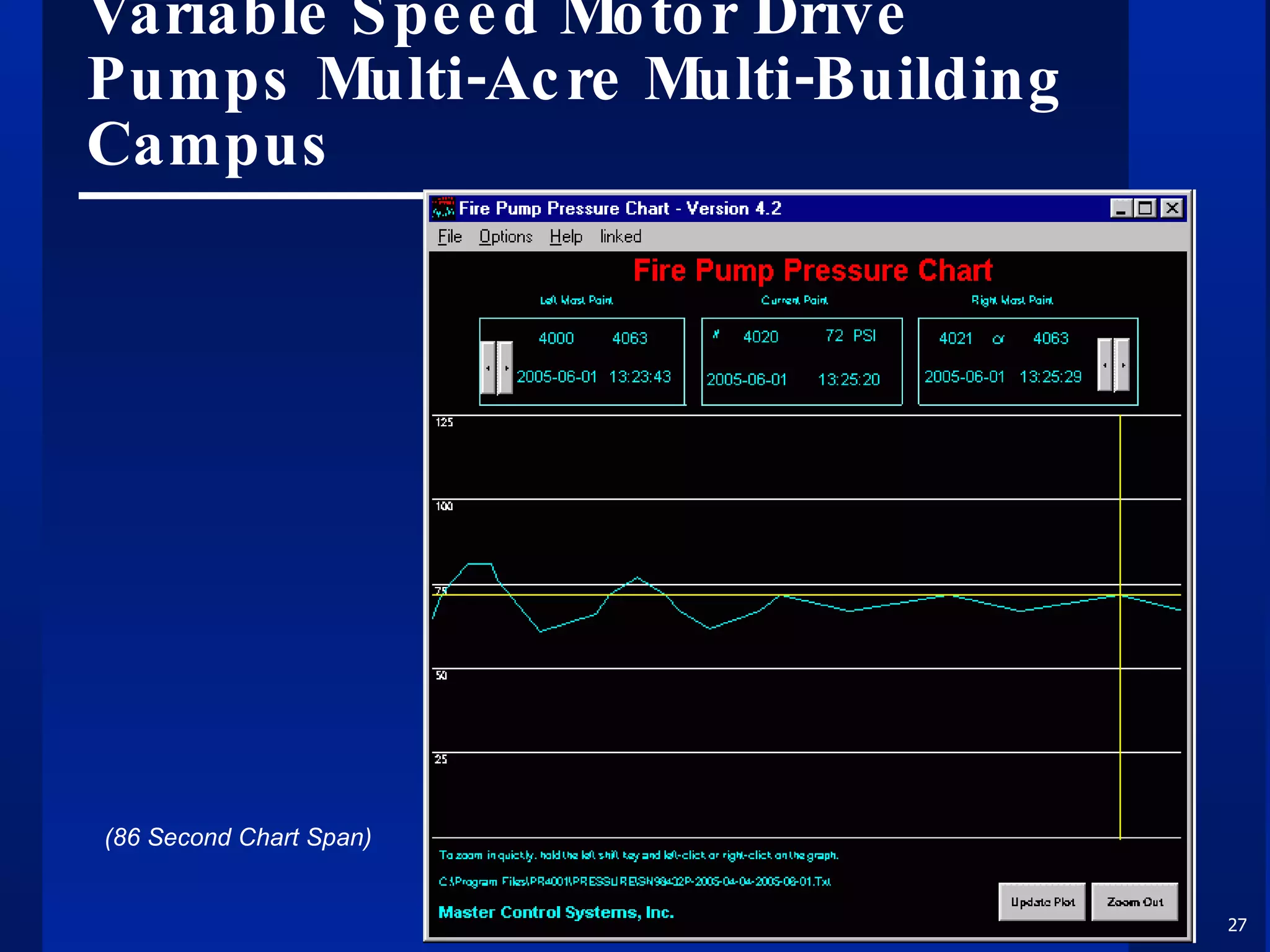
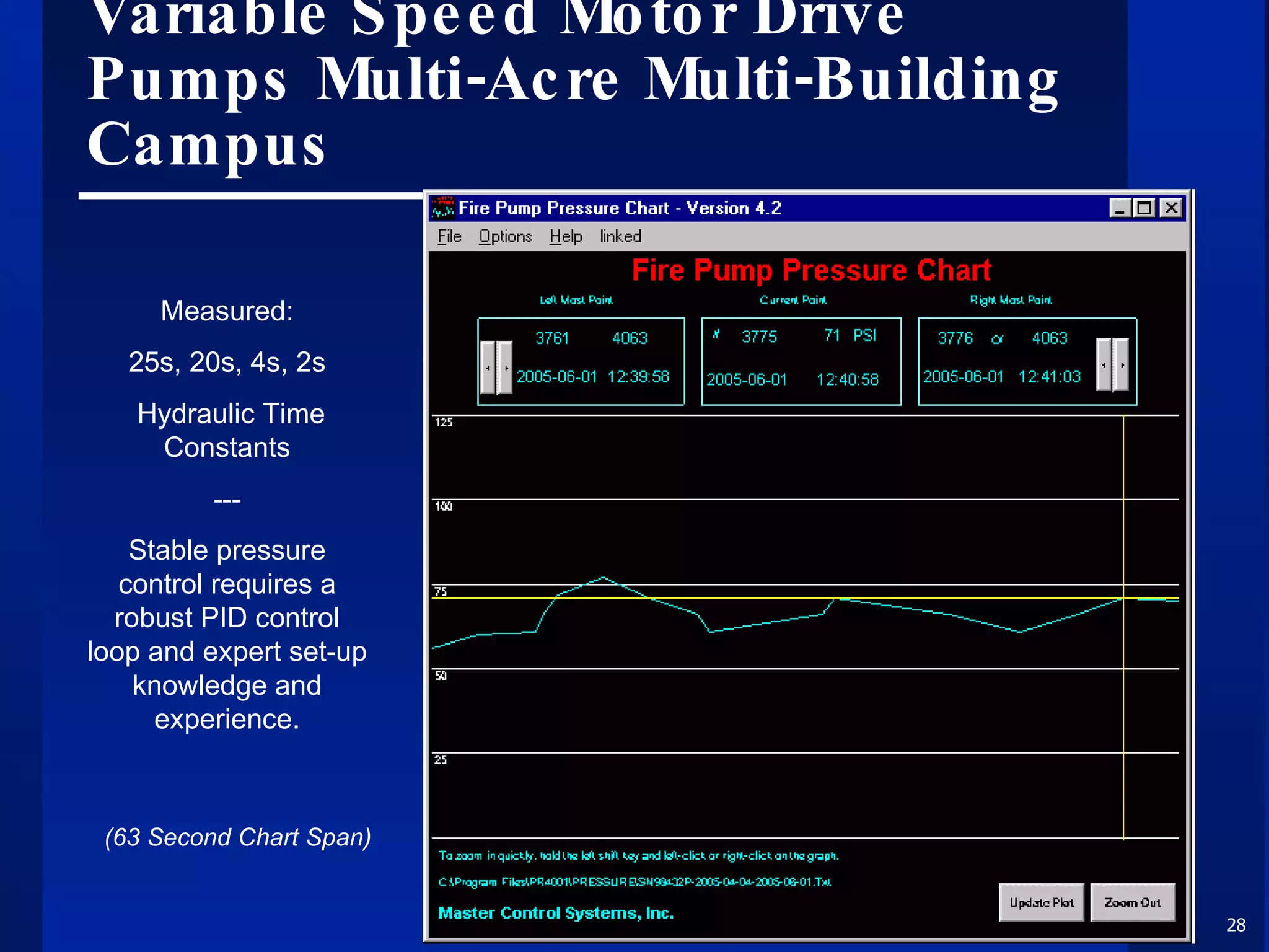
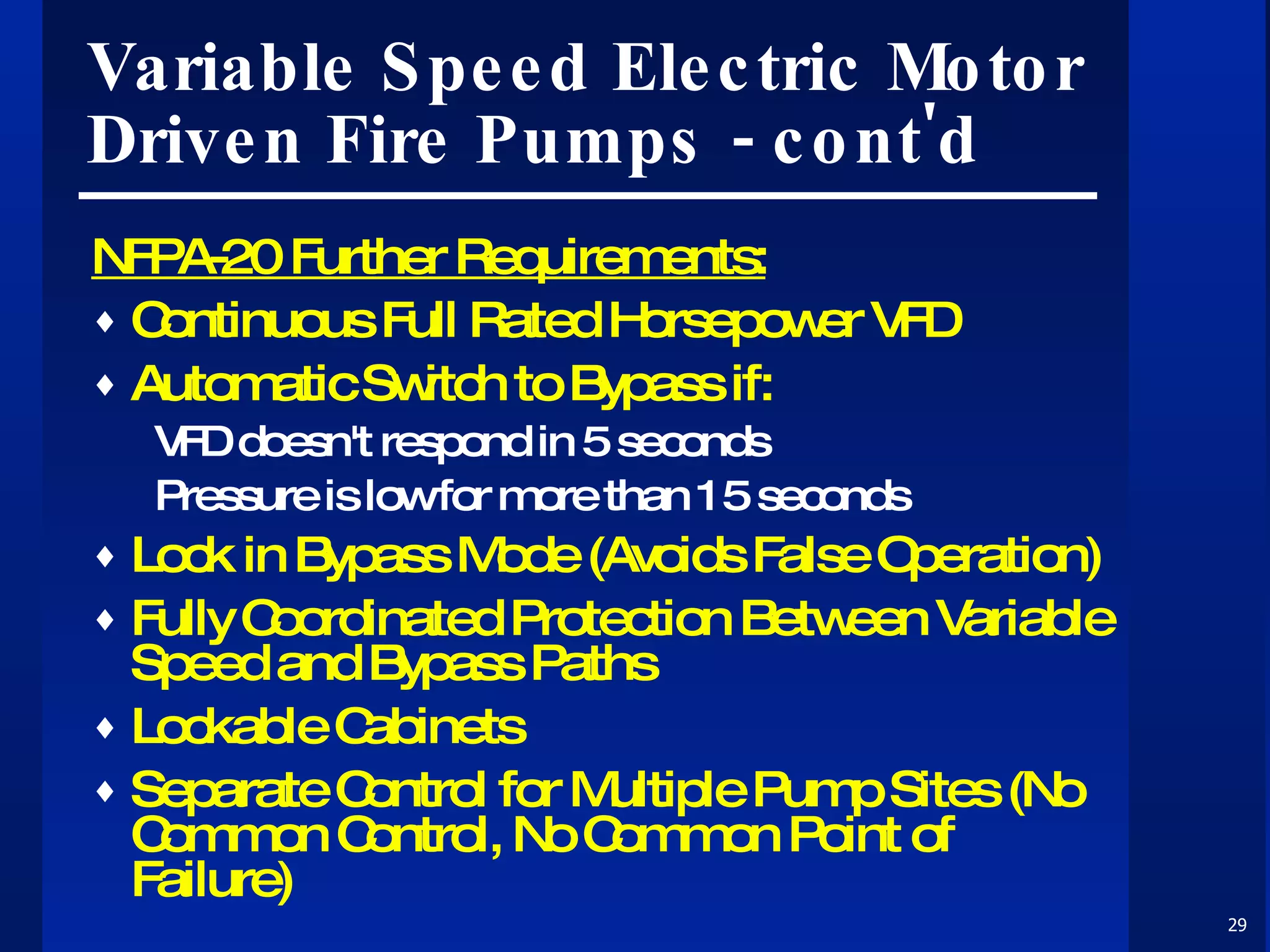
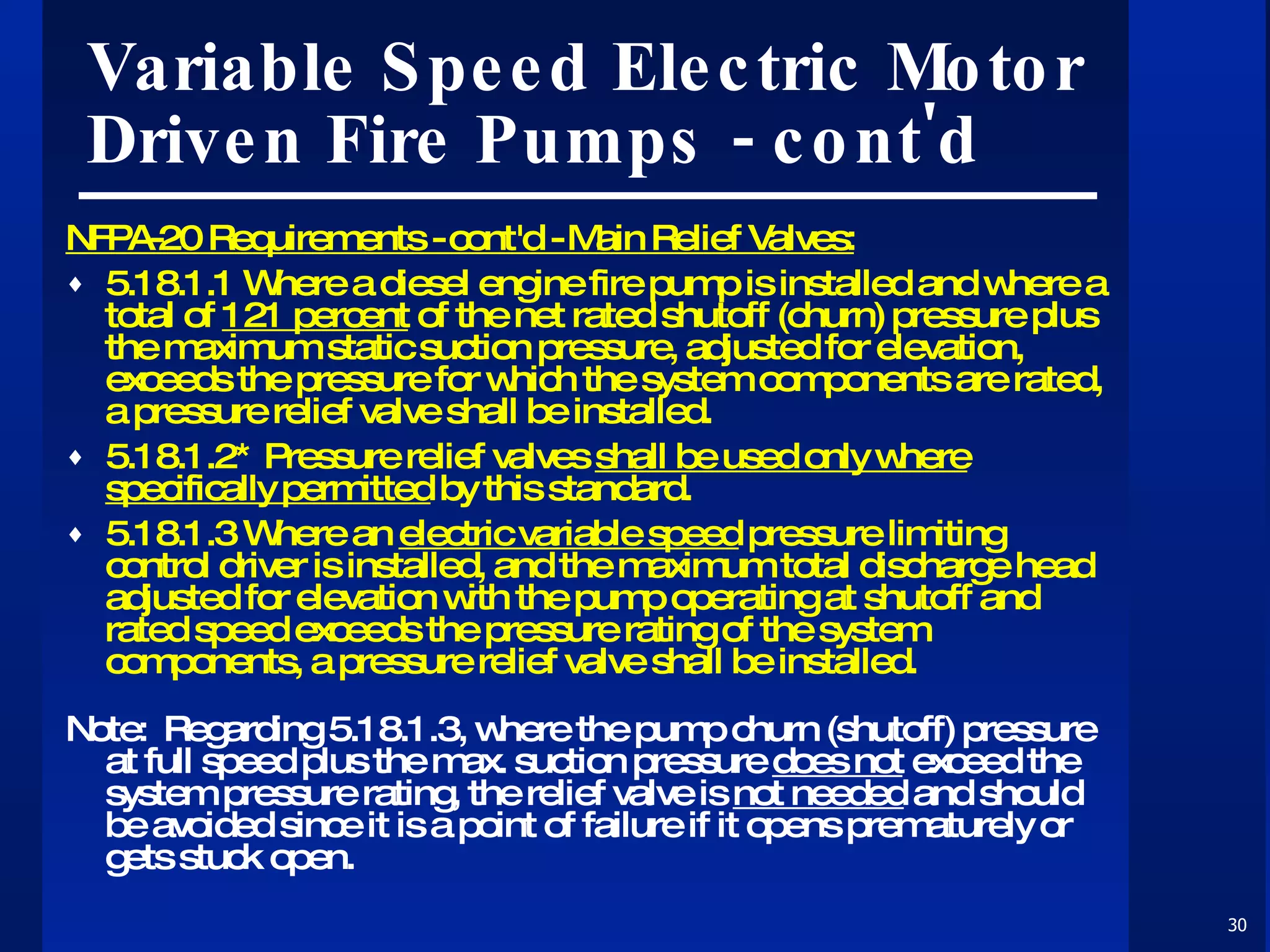
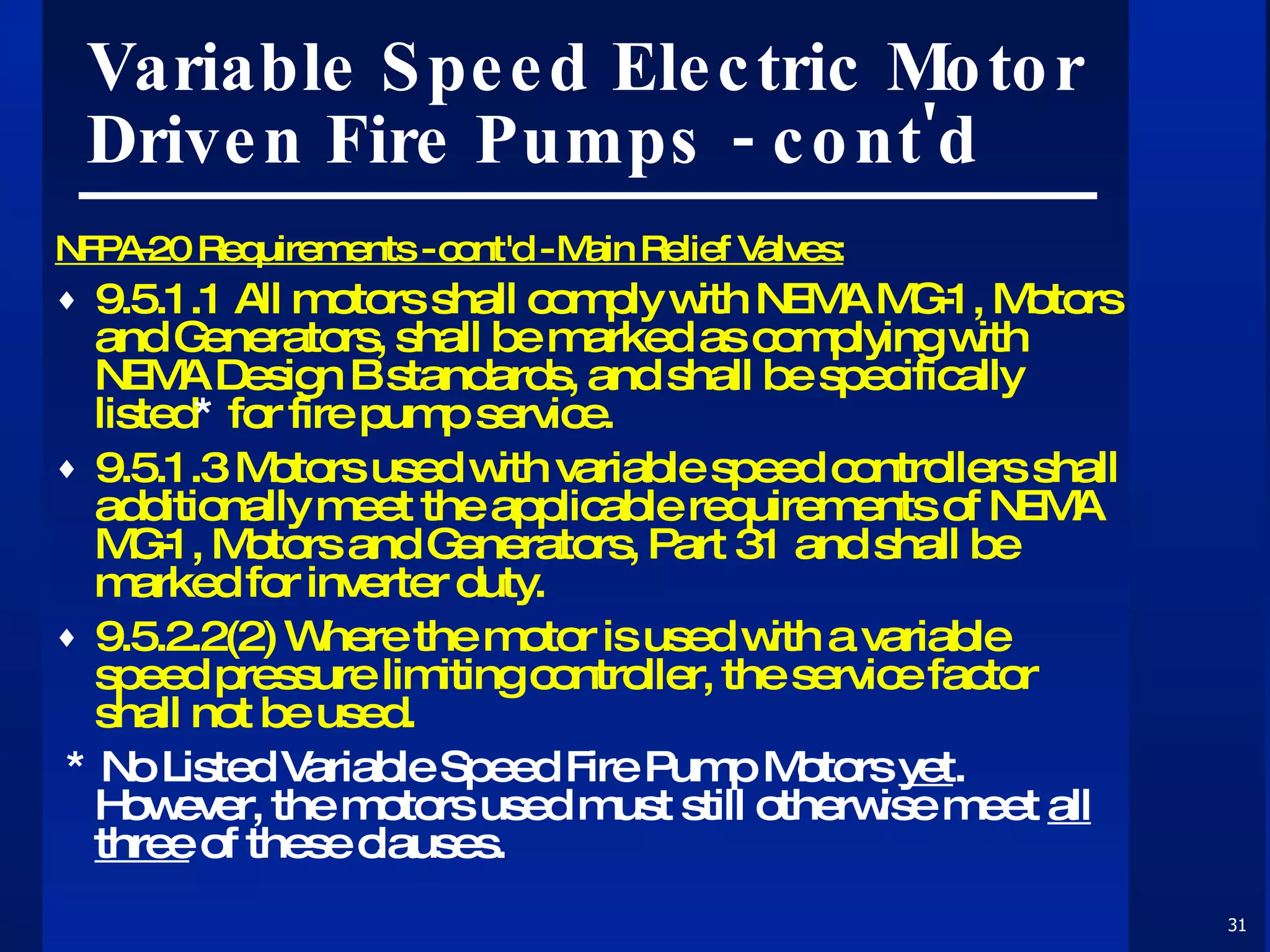
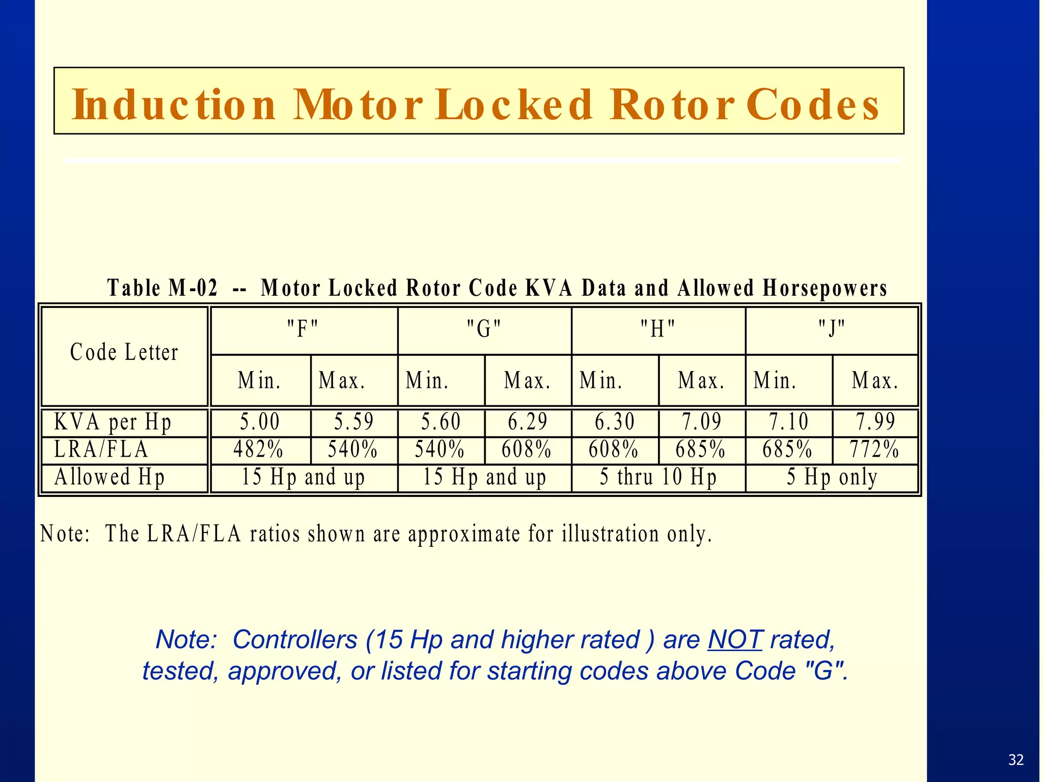
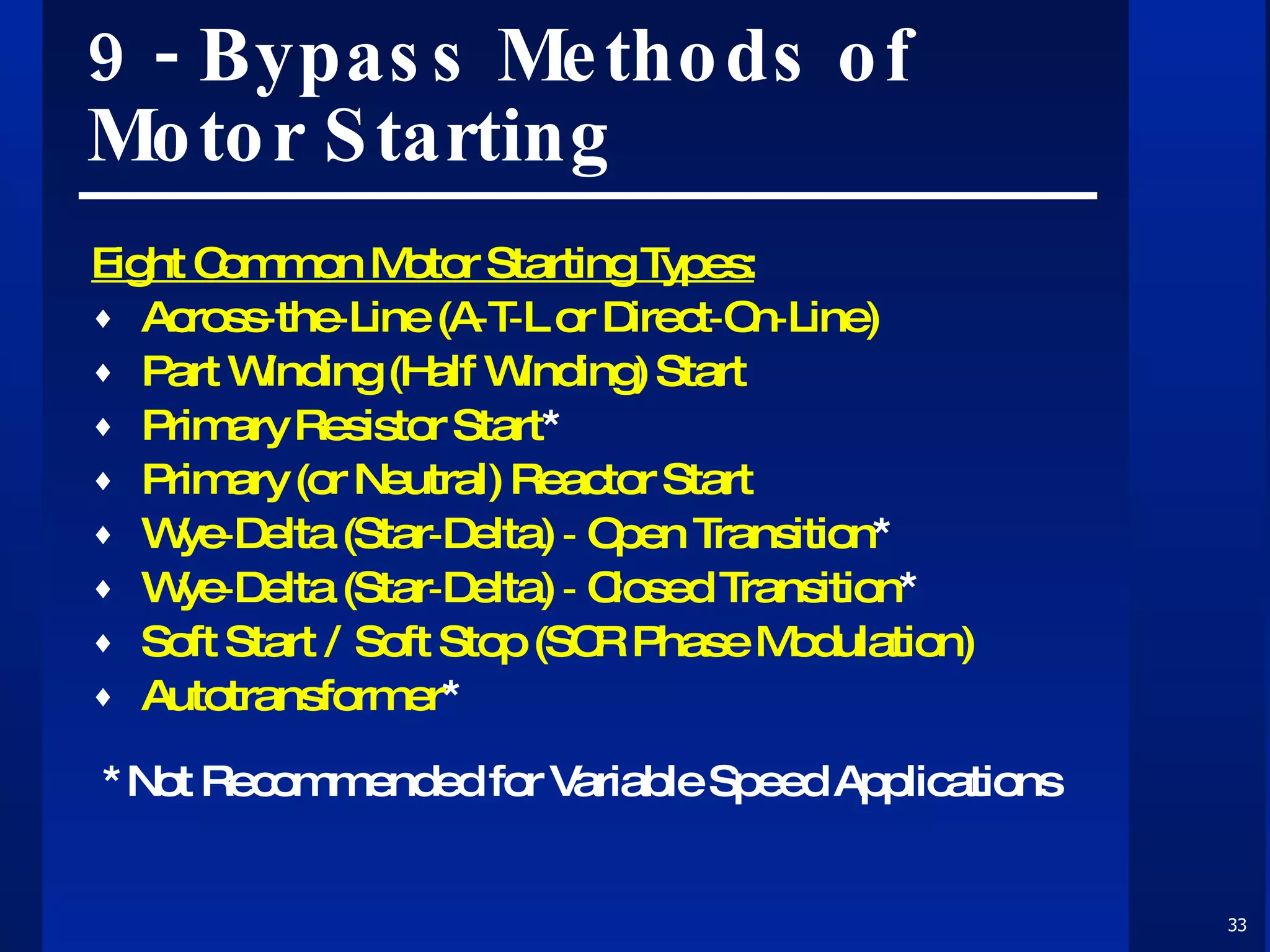
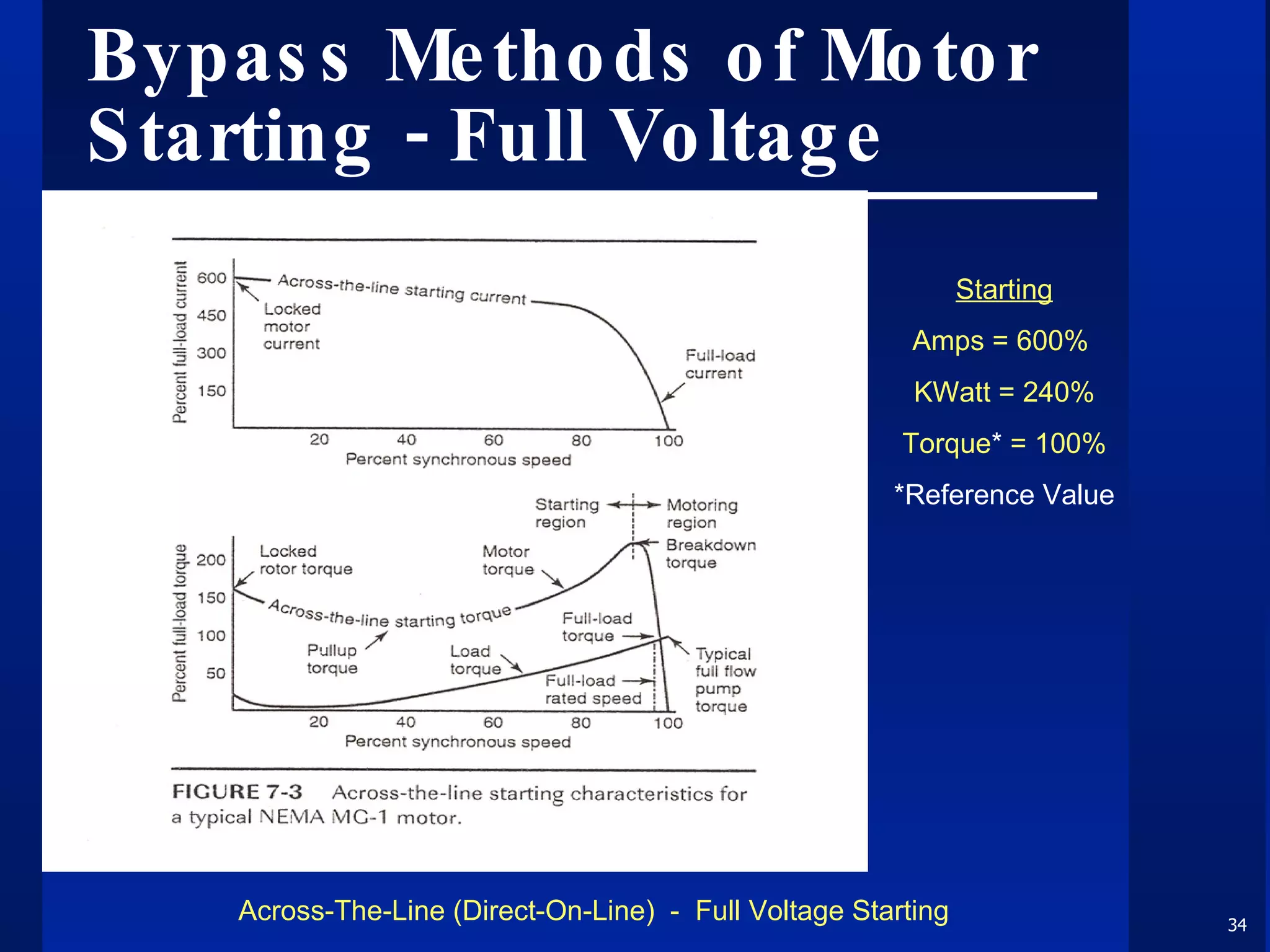
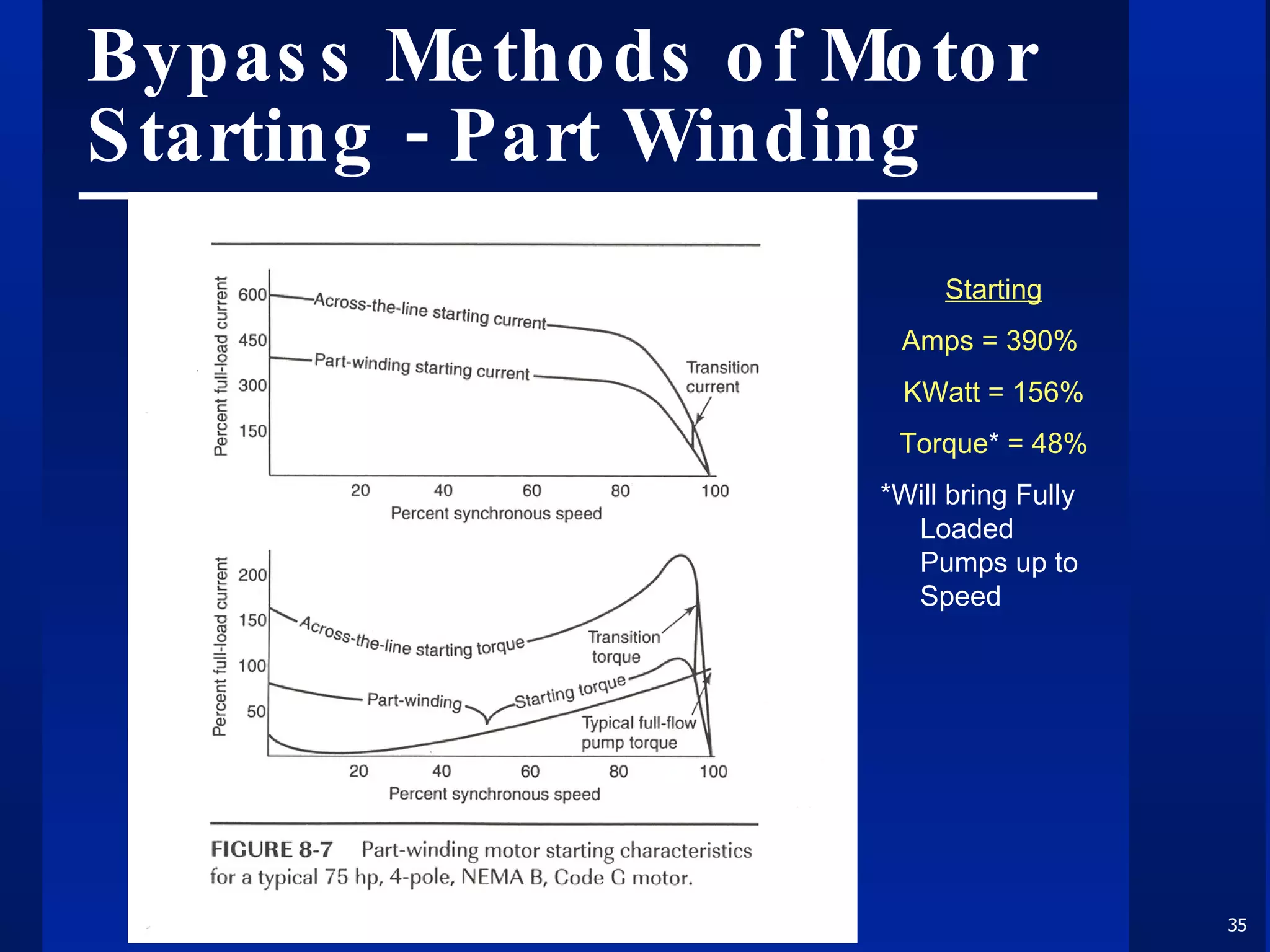
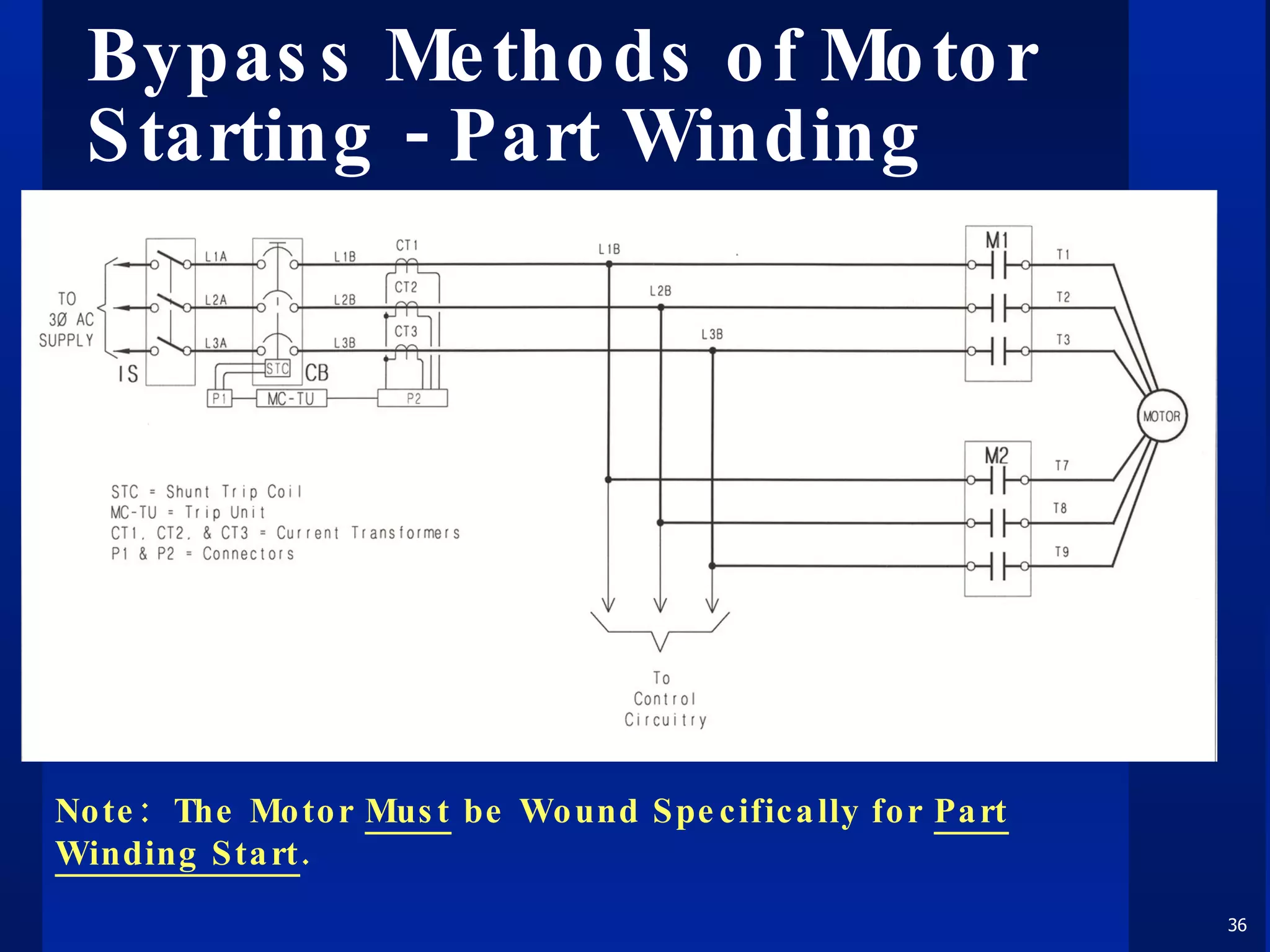
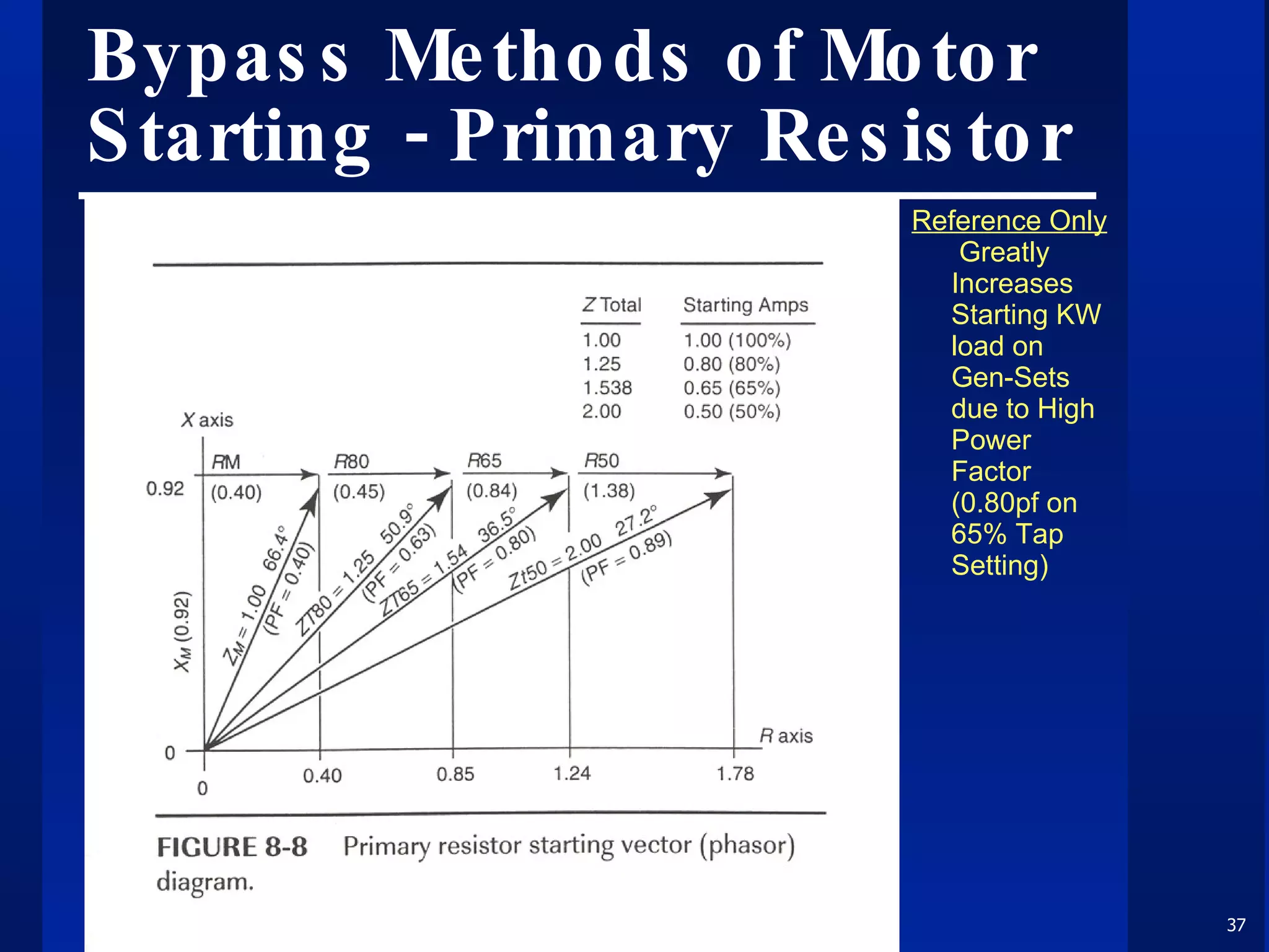
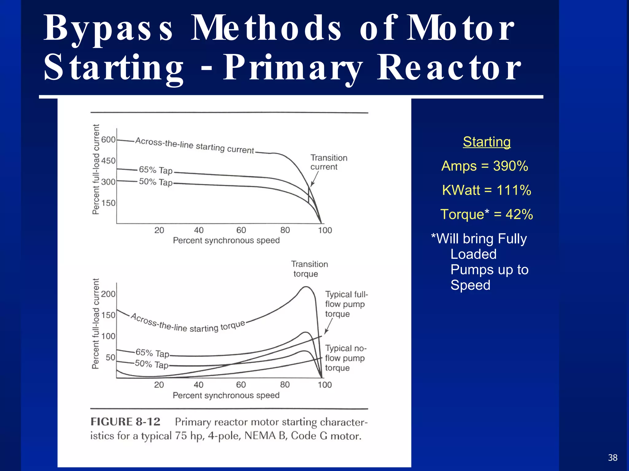
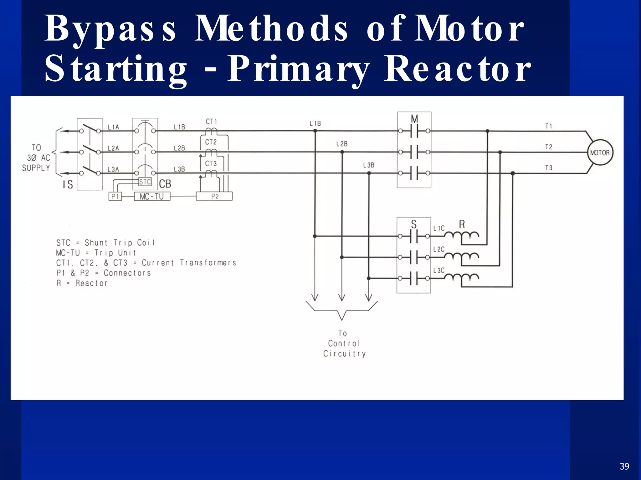
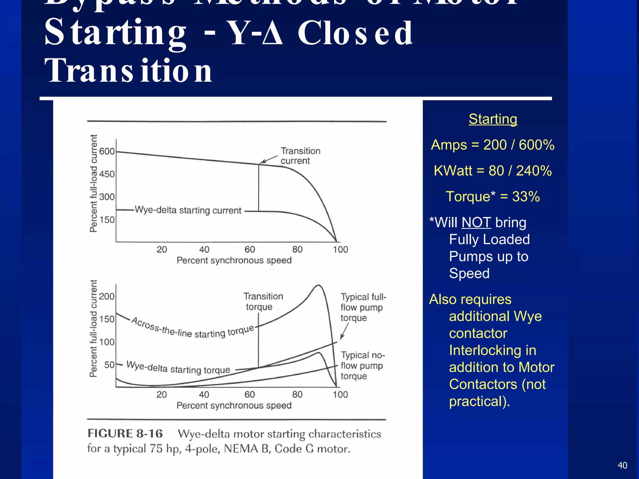
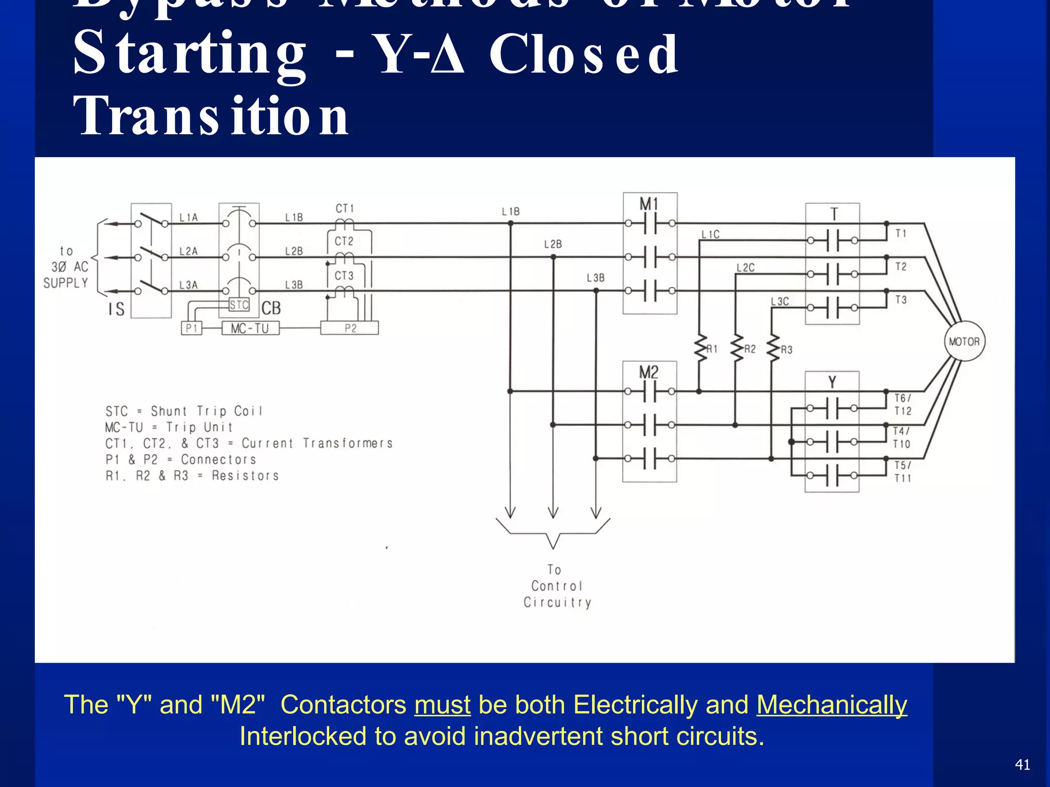
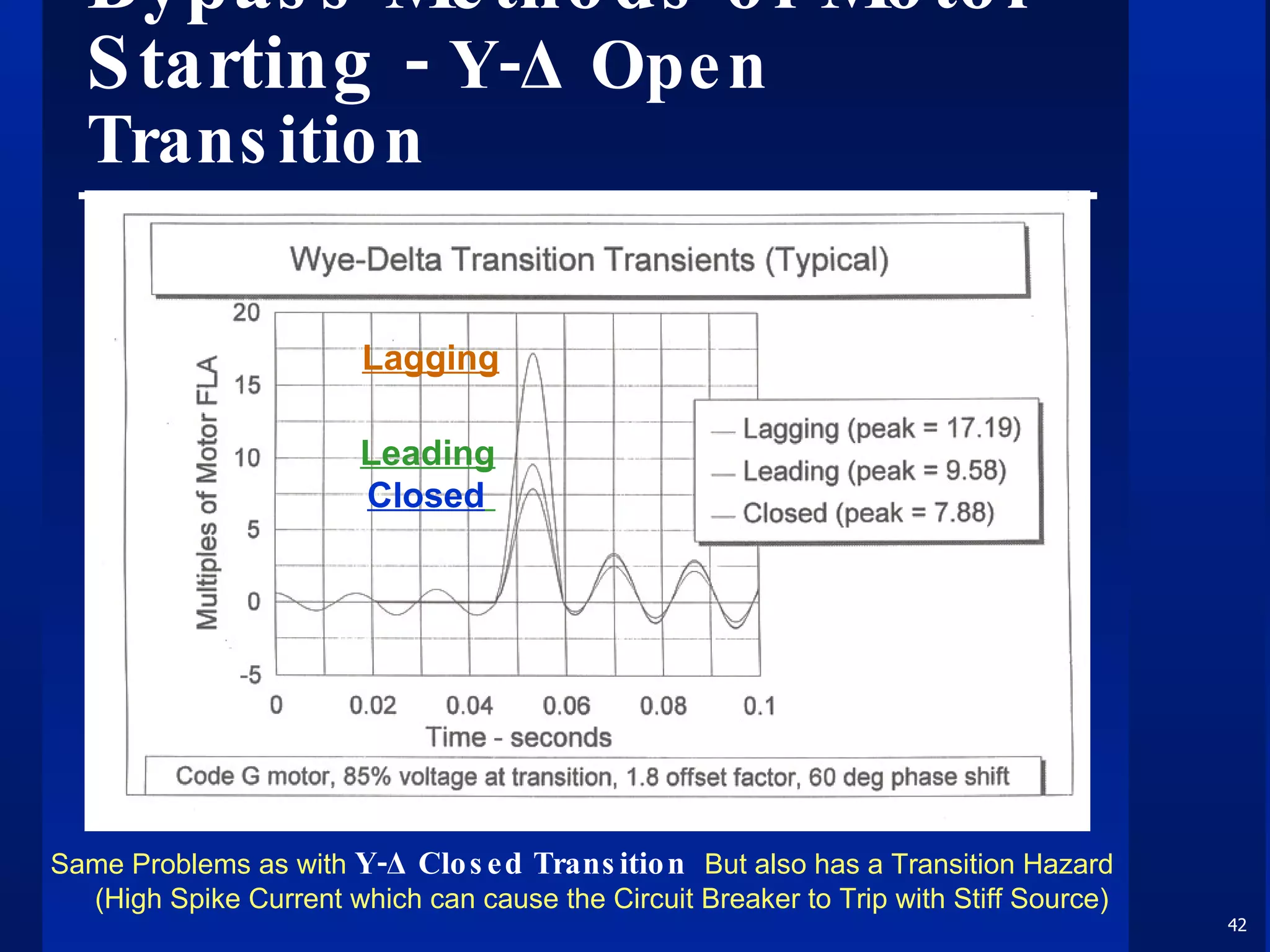
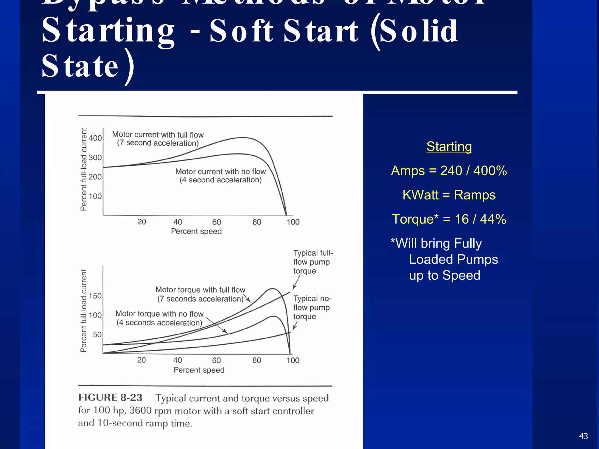
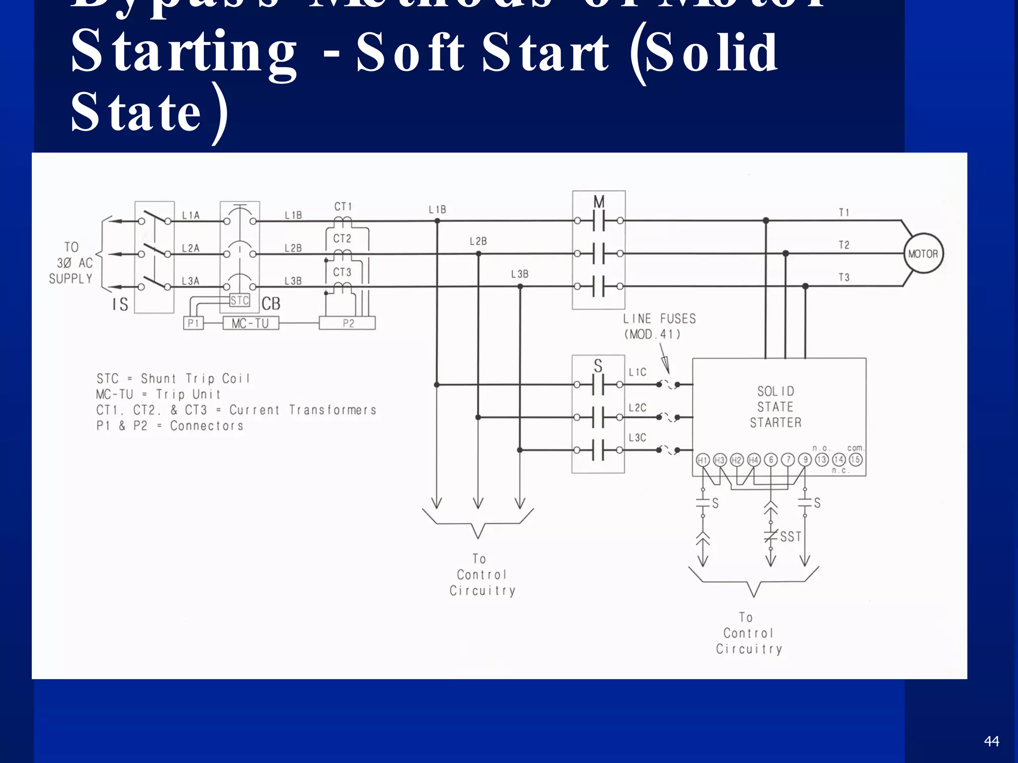
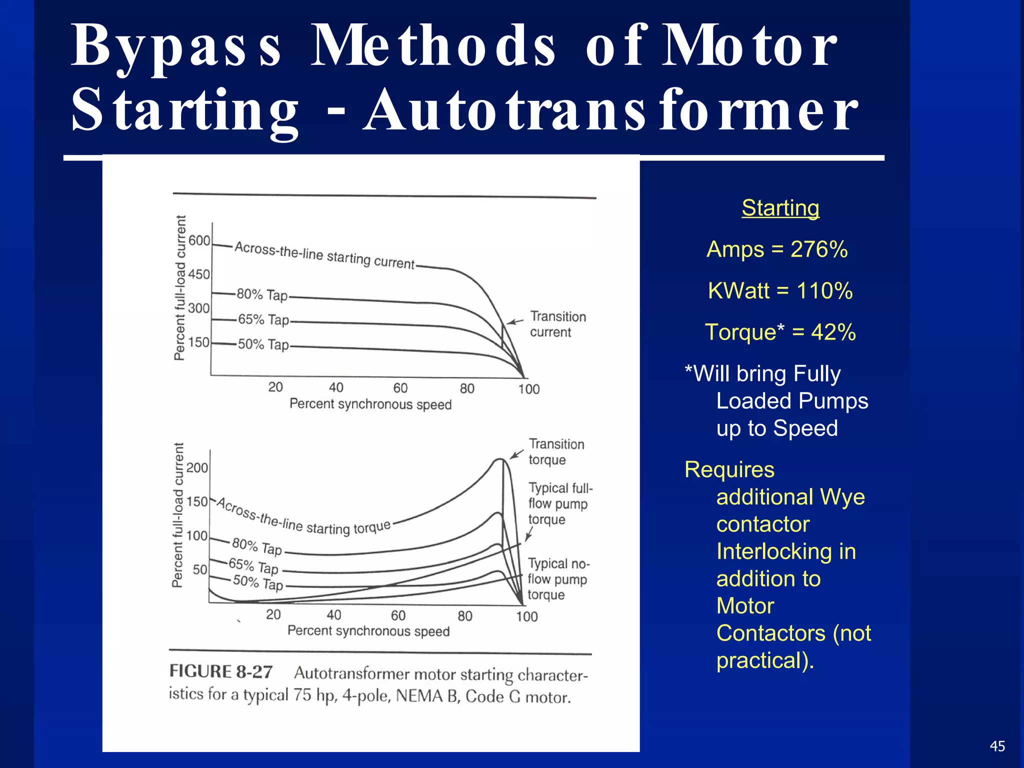
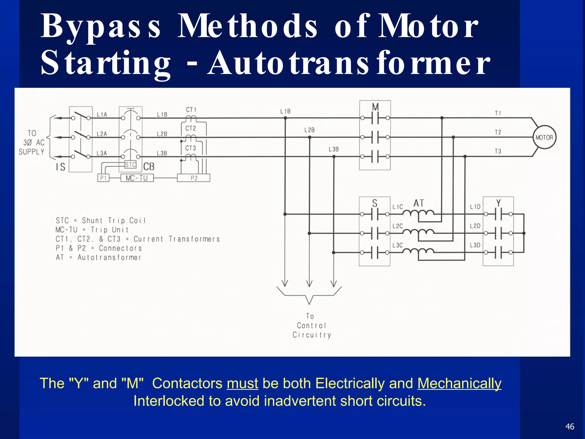
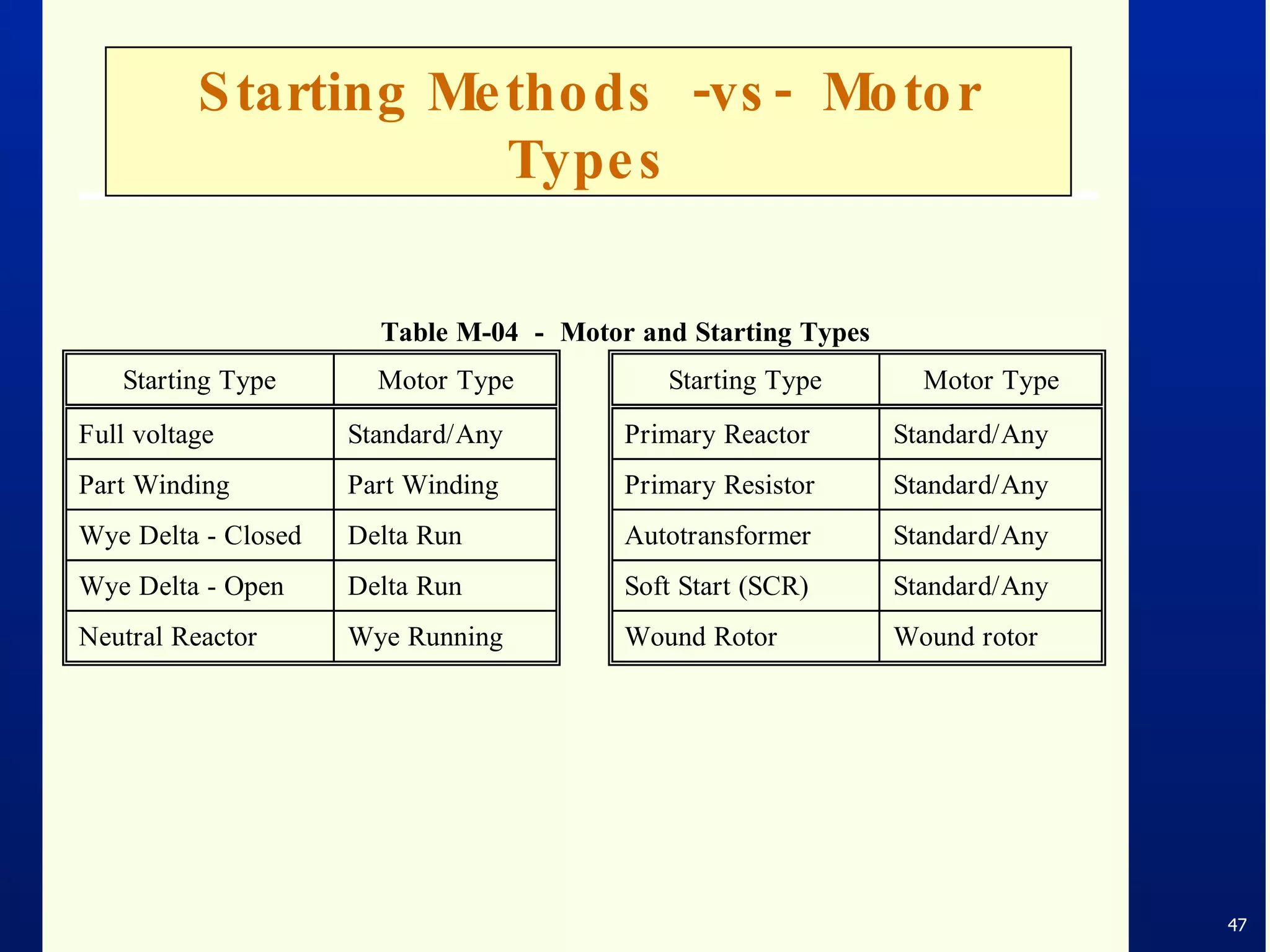
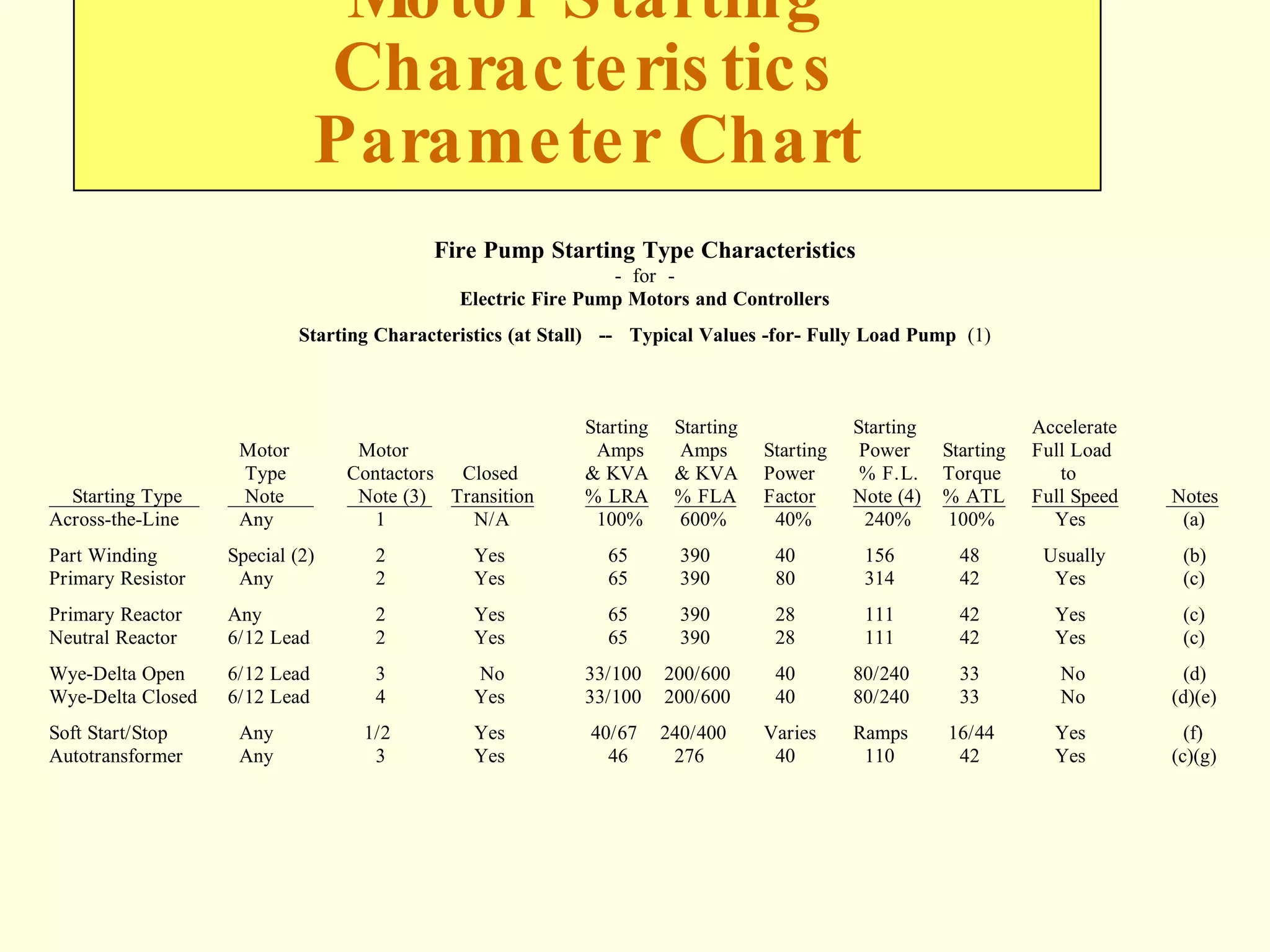
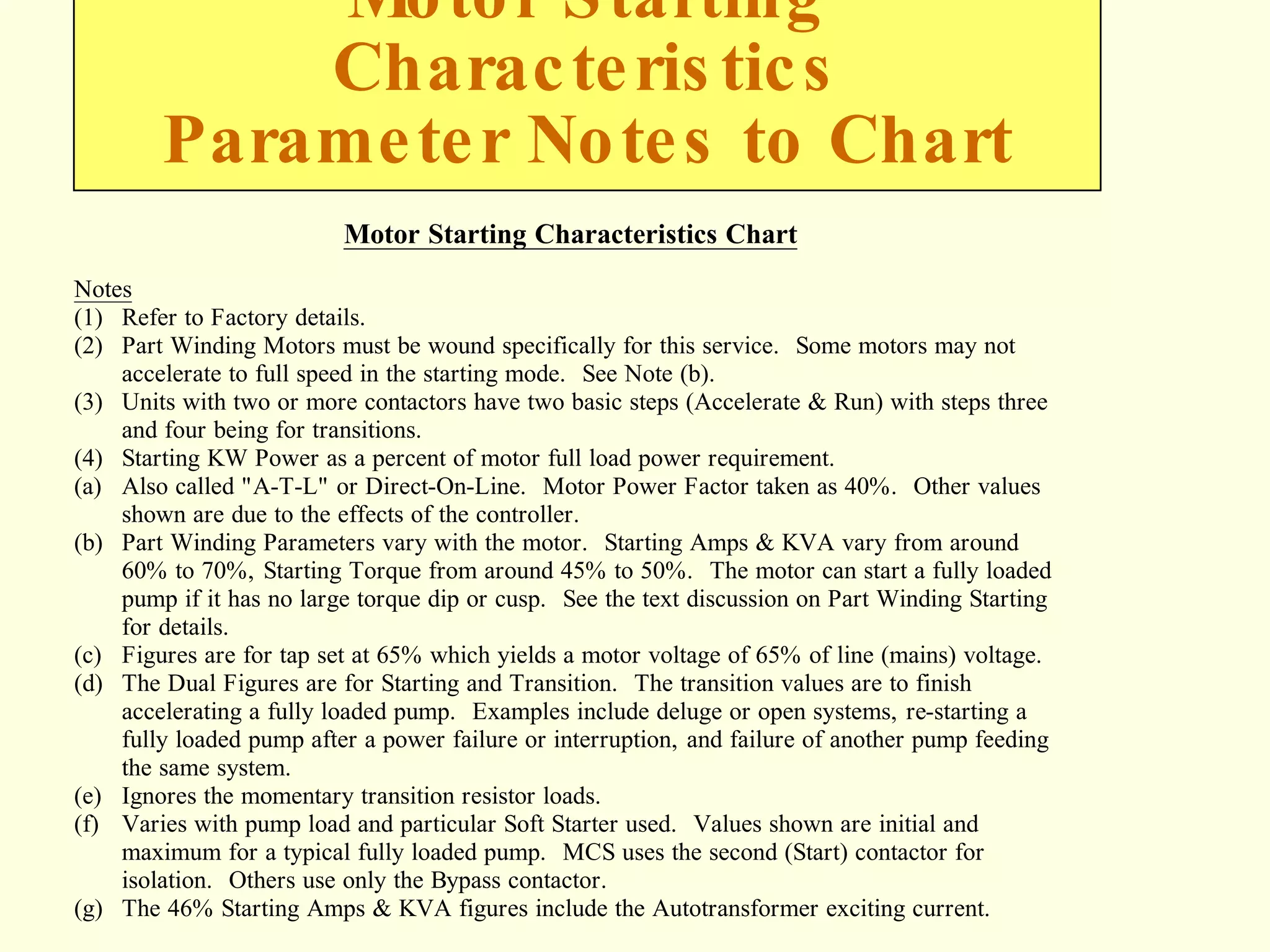
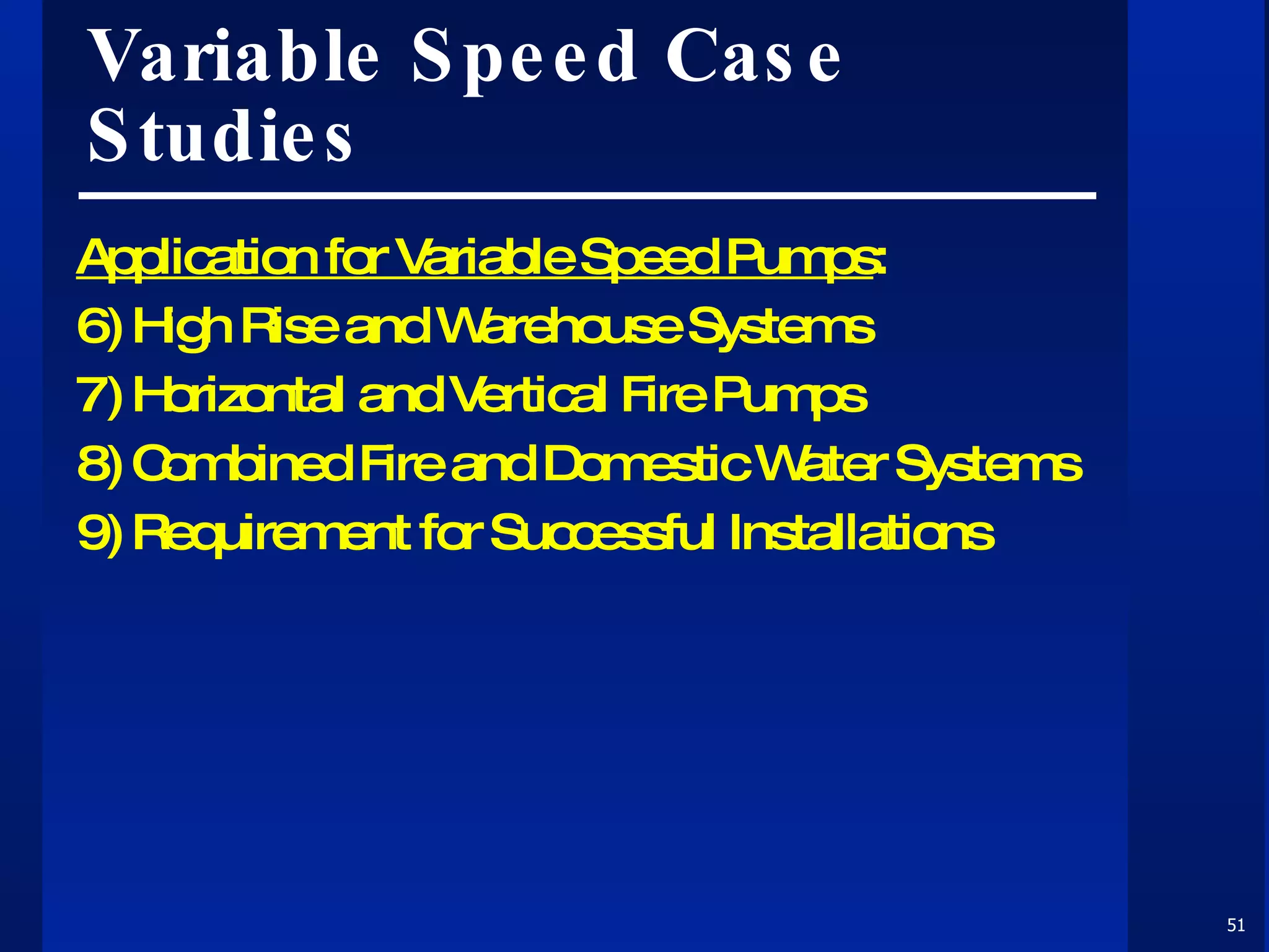
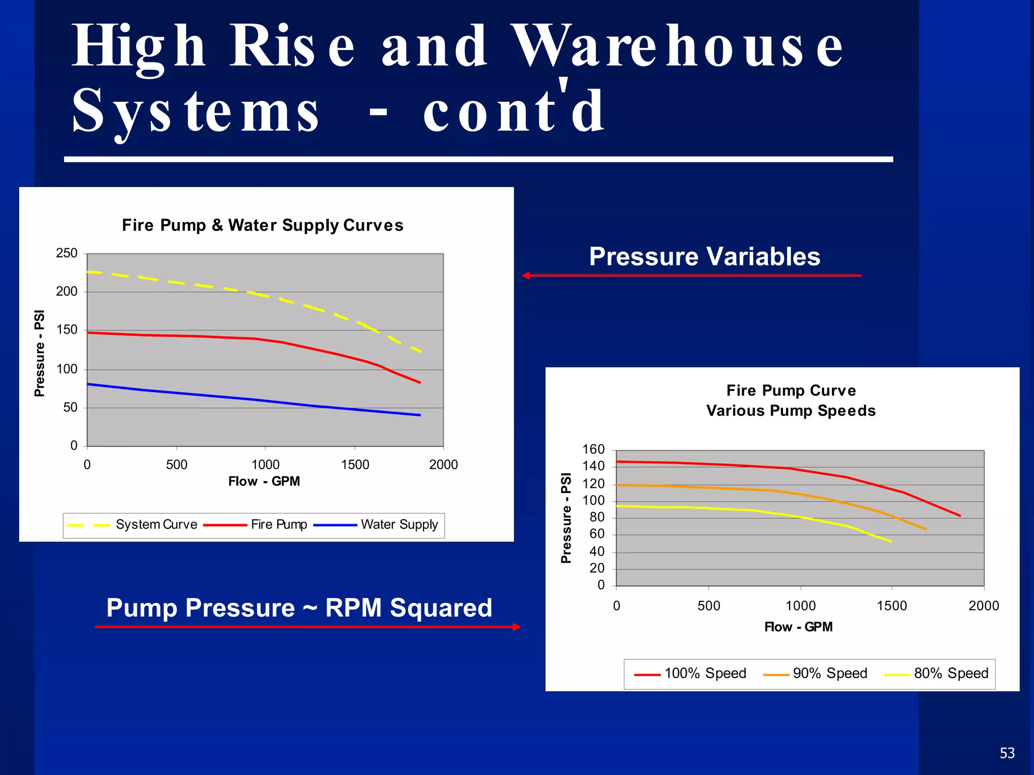
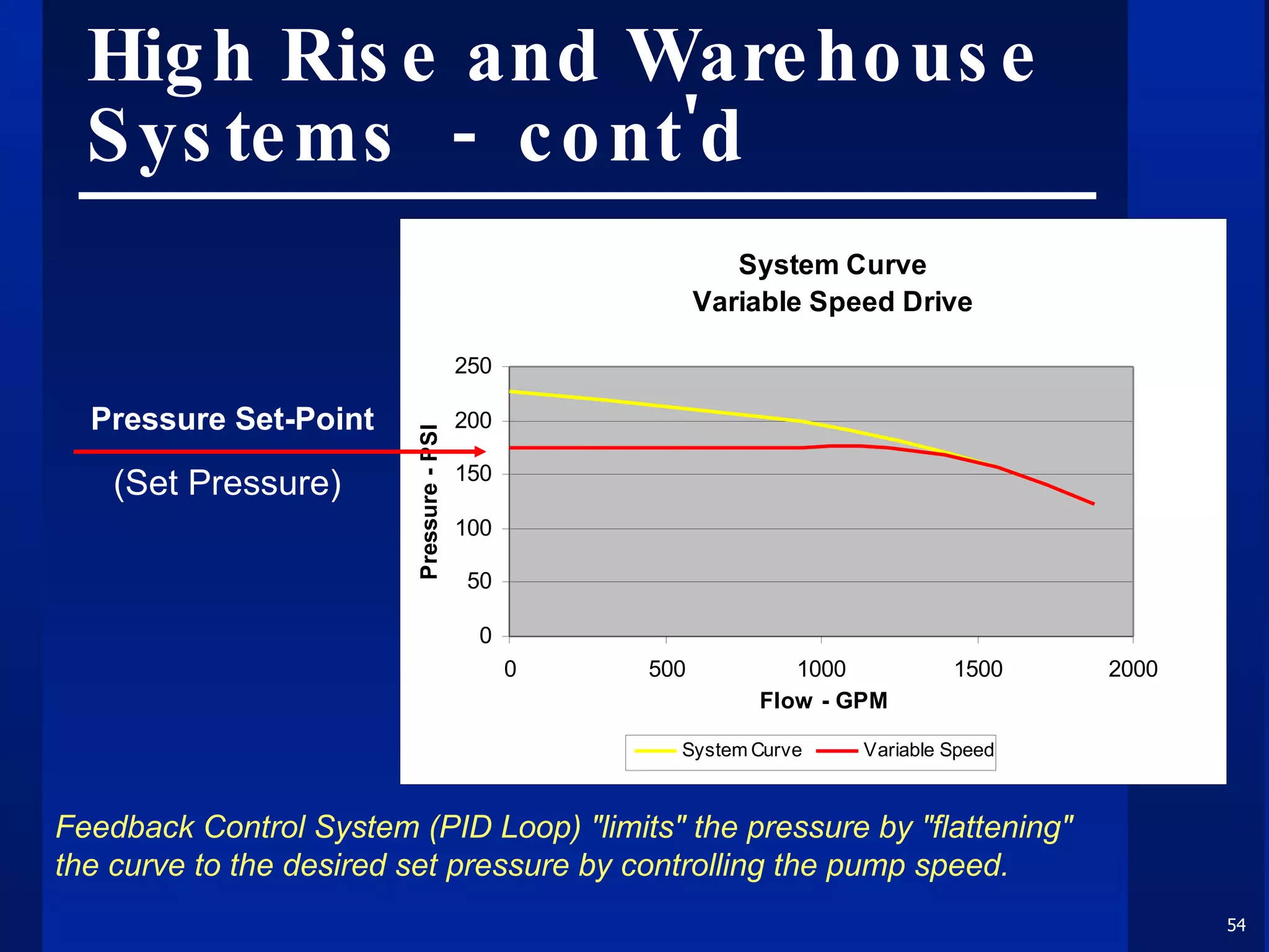
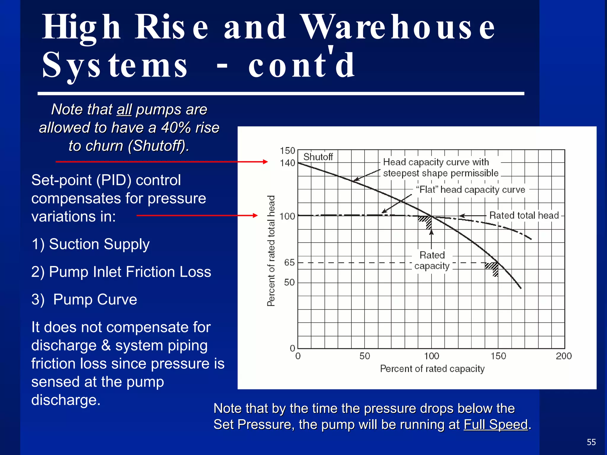
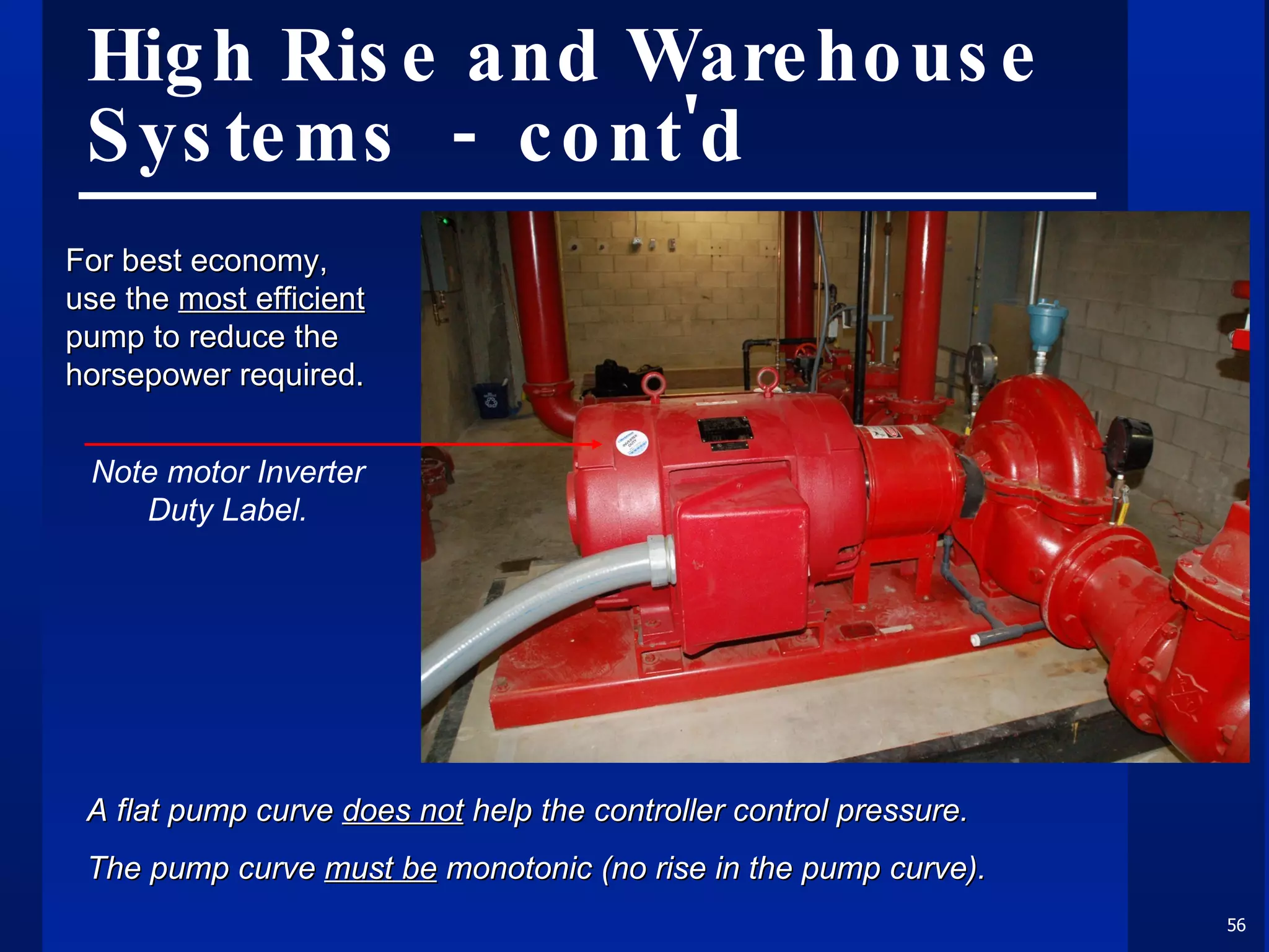
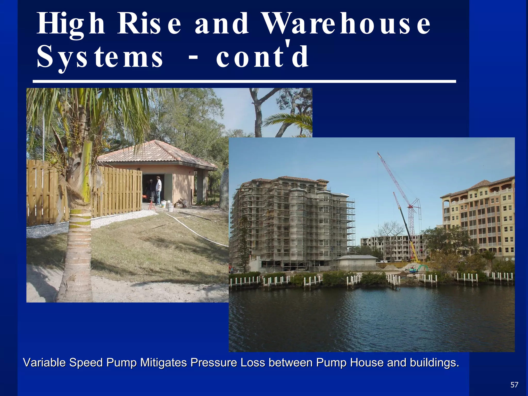
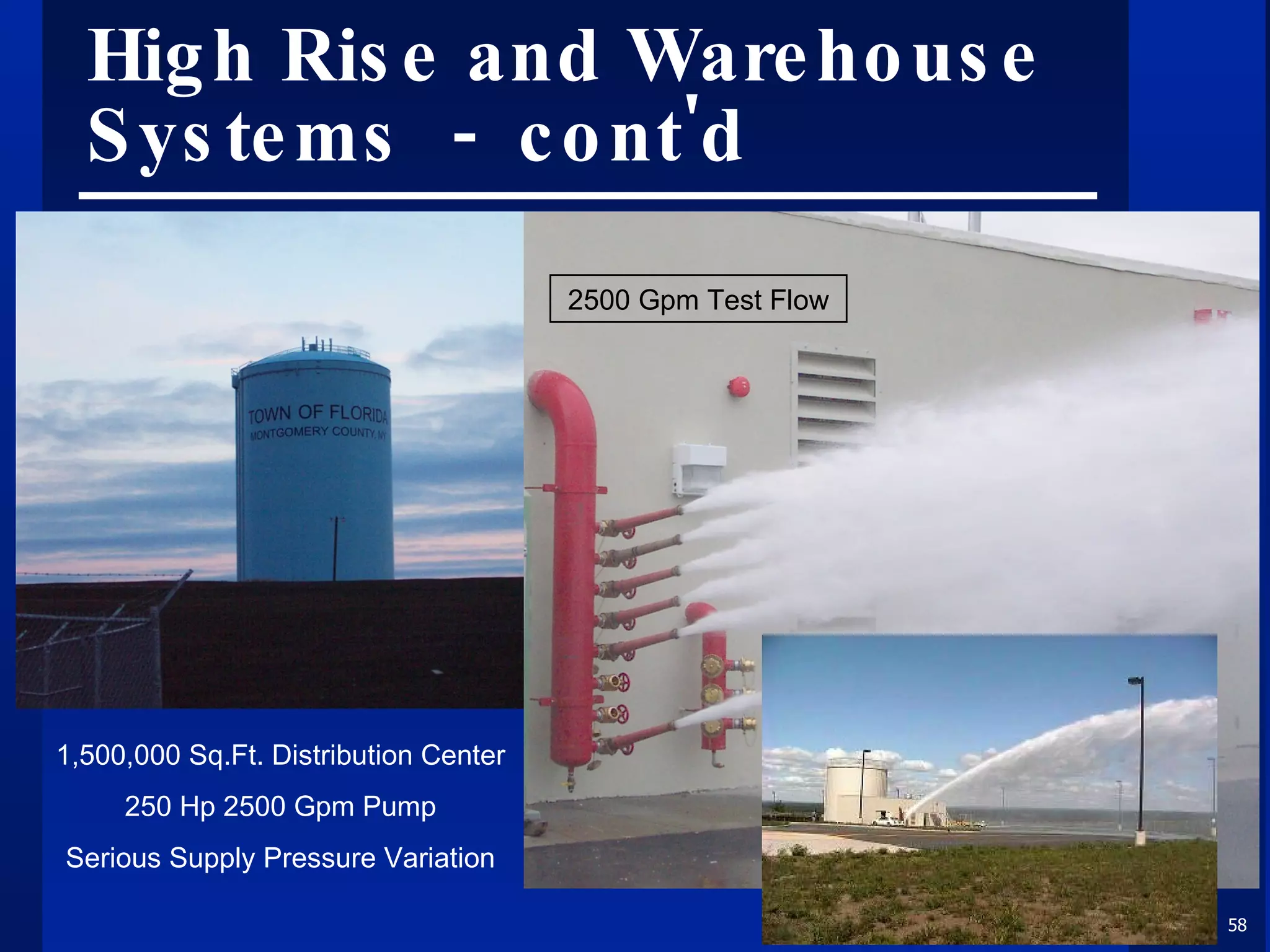
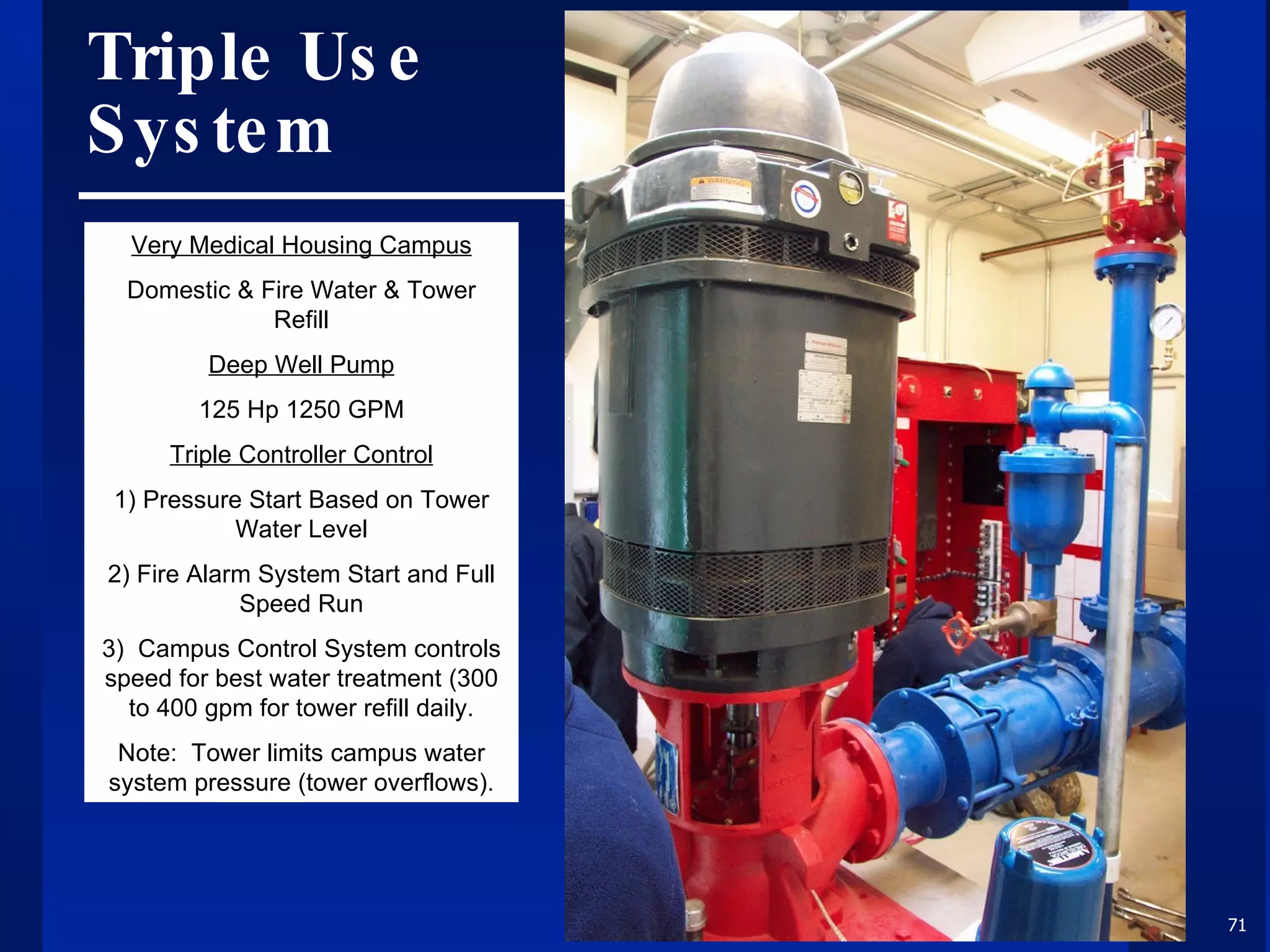
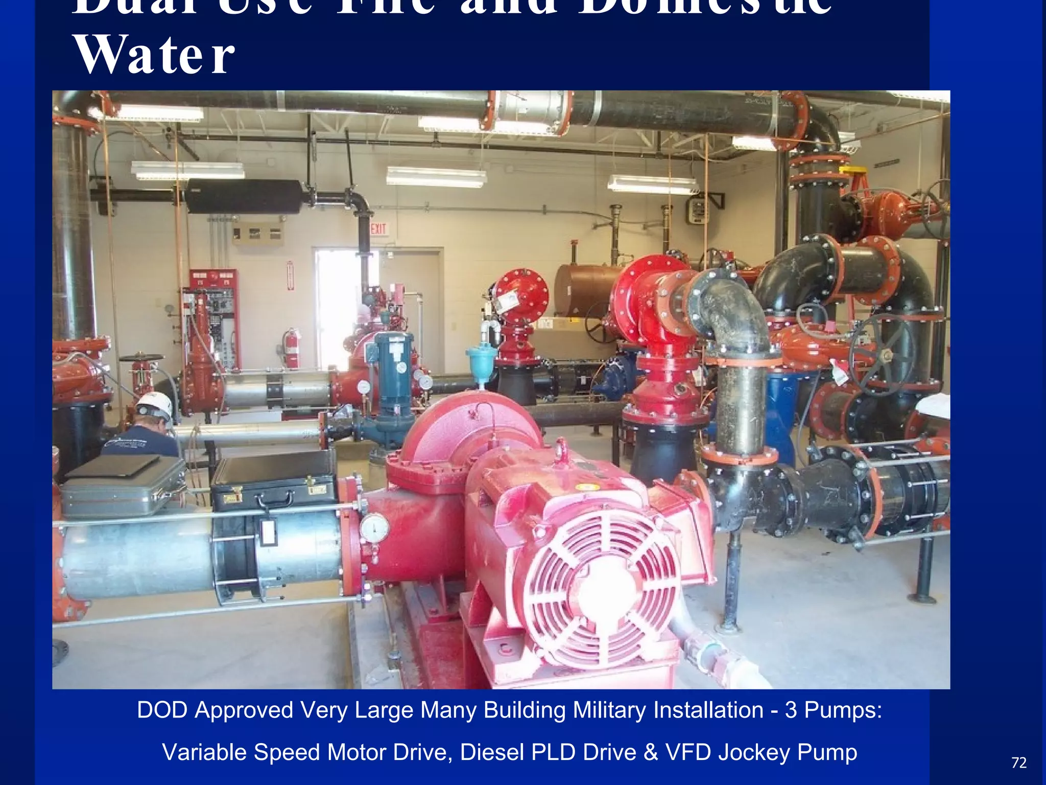
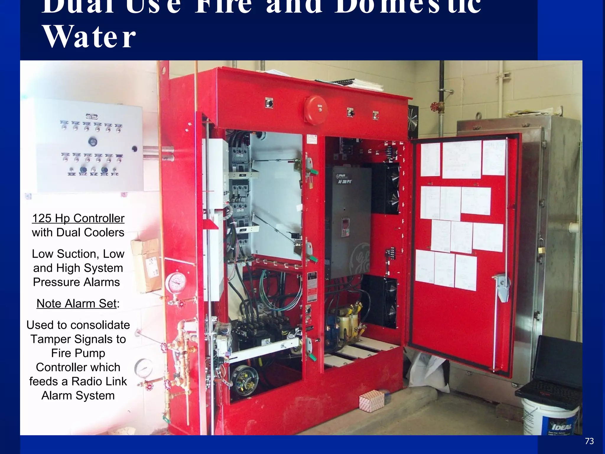
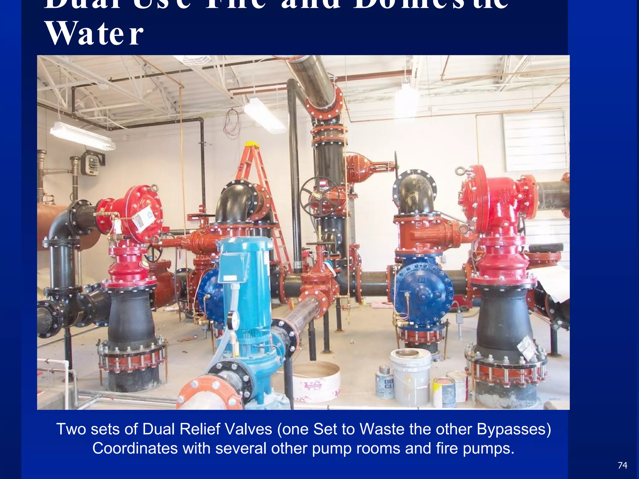
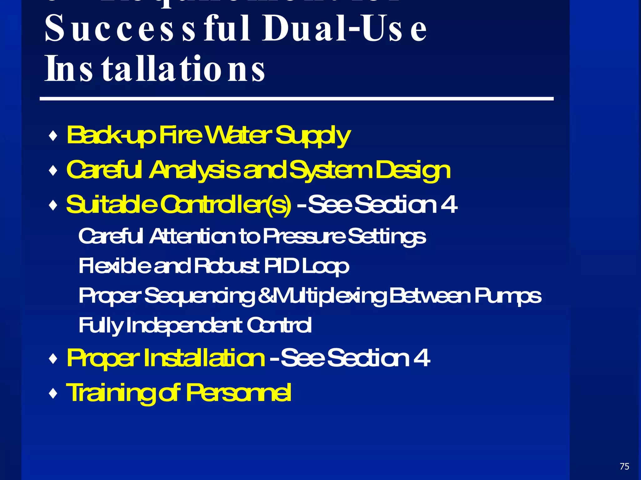
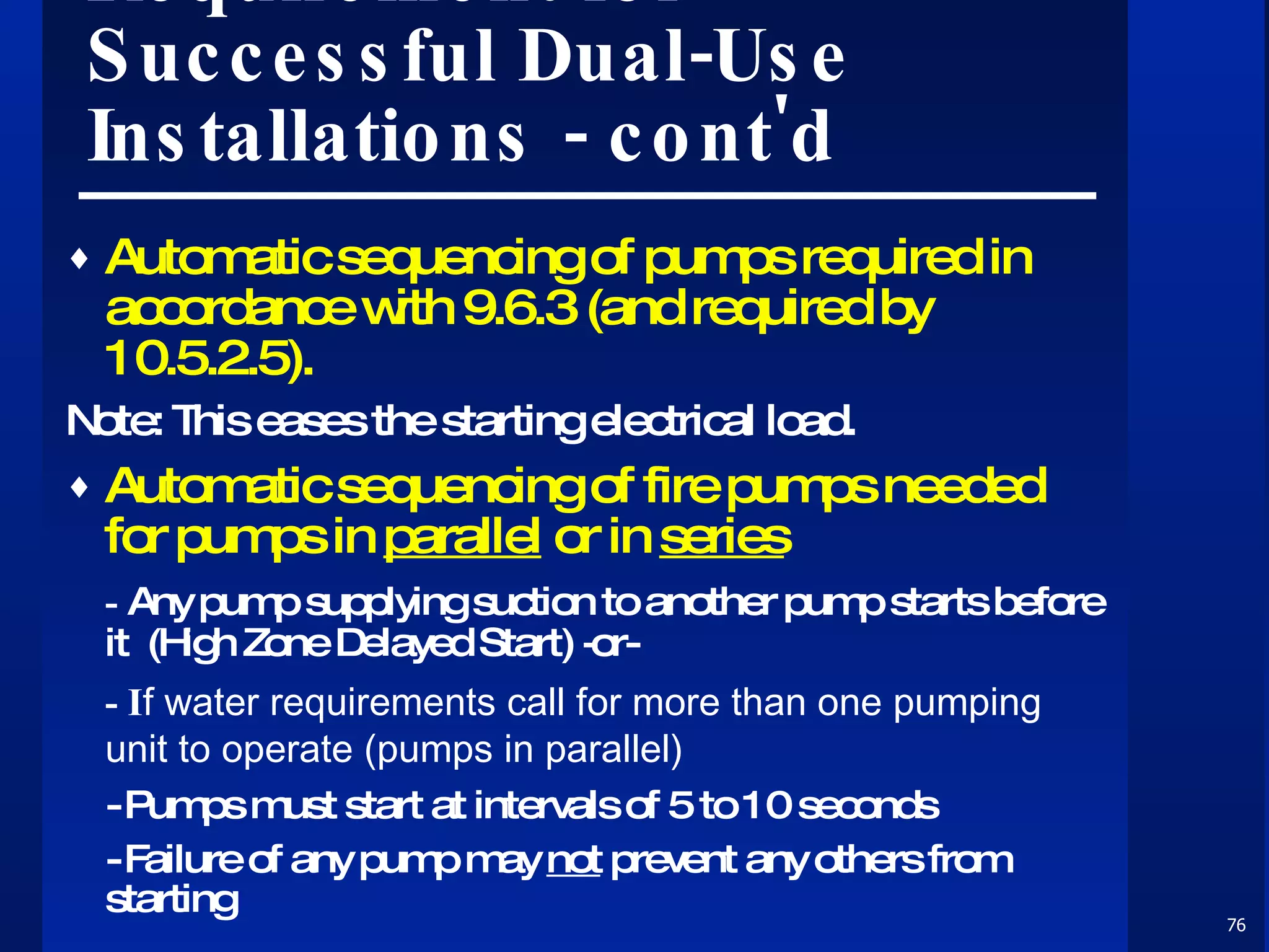
The document discusses sprinkler fire pumps system pressure control based on NFPA 20 - 2007, detailing methods such as break tanks, pressure regulating valves, and variable speed pumps. It outlines installation requirements and case studies related to high-rise and warehouse systems, focusing on the importance of pressure management and the performance of variable-speed electric motor-driven fire pumps. Various motor starting methods and their applications in maintaining pump operation and pressure stability are also covered.


