Download as PPS, PPTX


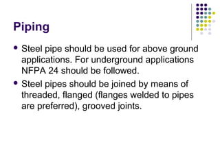


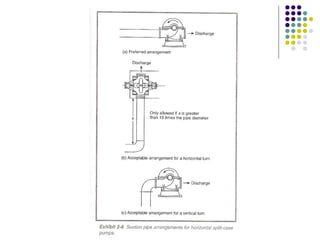


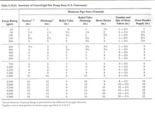


- Fire pumps are centrifugal pumps selected to operate between 90-140% of rated capacity and less than 150% to avoid overpressure. - Pump rooms require 1-hour fire rated separation, emergency lighting, ventilation, and drainage. - Suction and discharge piping must be sized properly and have the correct fittings like gauges, valves, and relief valves. Jockey pumps maintain system pressure. - Electric and diesel fire pump controllers prioritize system operation over equipment protection to ensure reliable fire suppression.


