Downloaded 163 times


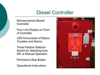


The document provides a detailed overview of the B-Series diesel fire pump controller, outlining its functions, operational instructions, testing protocols, and electrical schematics. It covers the controller's capabilities such as monitoring pressure, starting/stopping the engine, and safety features, along with procedures to test manual and automatic operations. Additionally, it discusses the connections needed for various alarms and equipment, emphasizing the importance of proper installation and testing for optimal performance.


