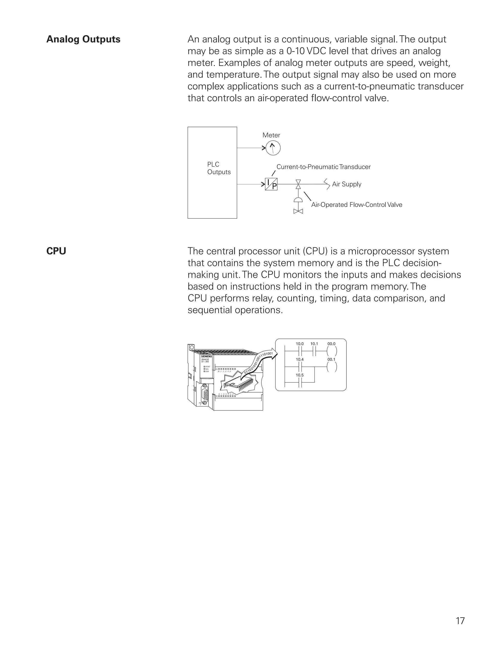
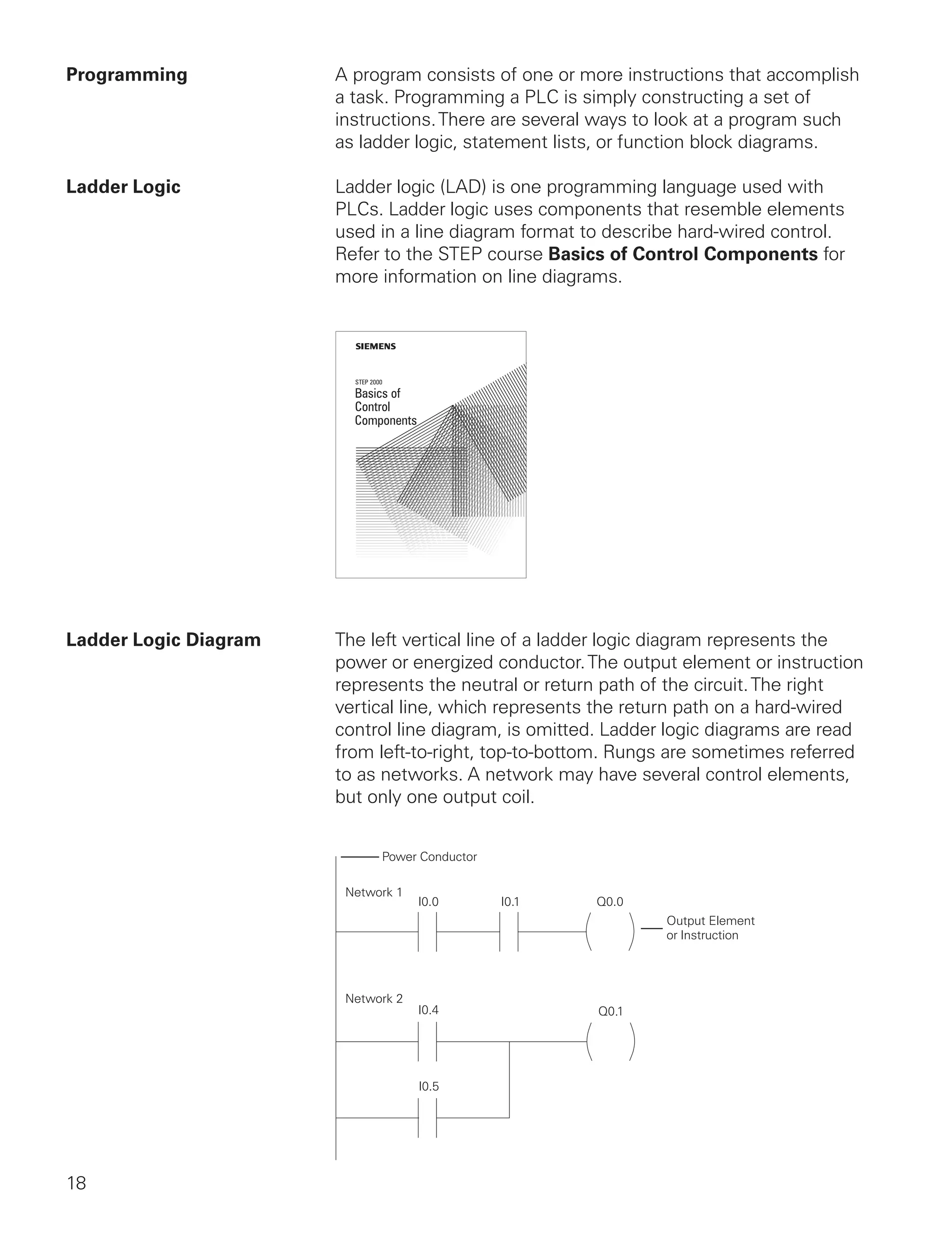
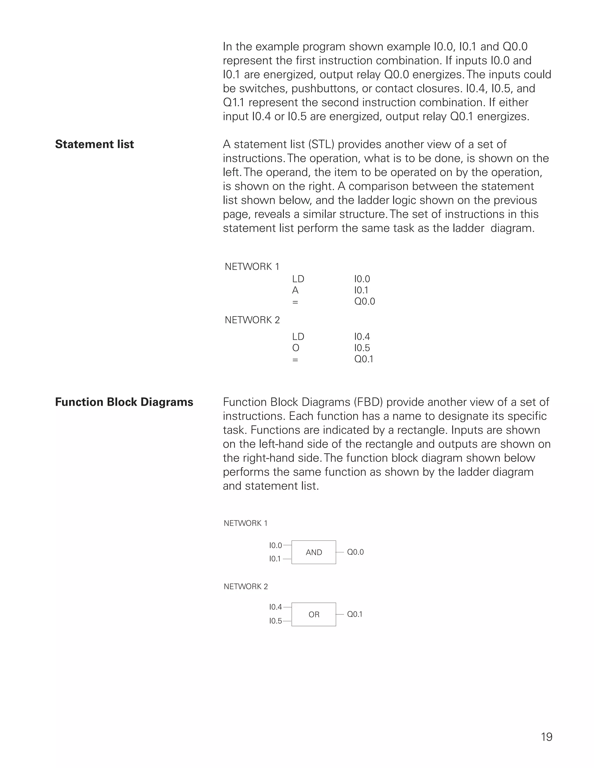
Downloaded 446 times
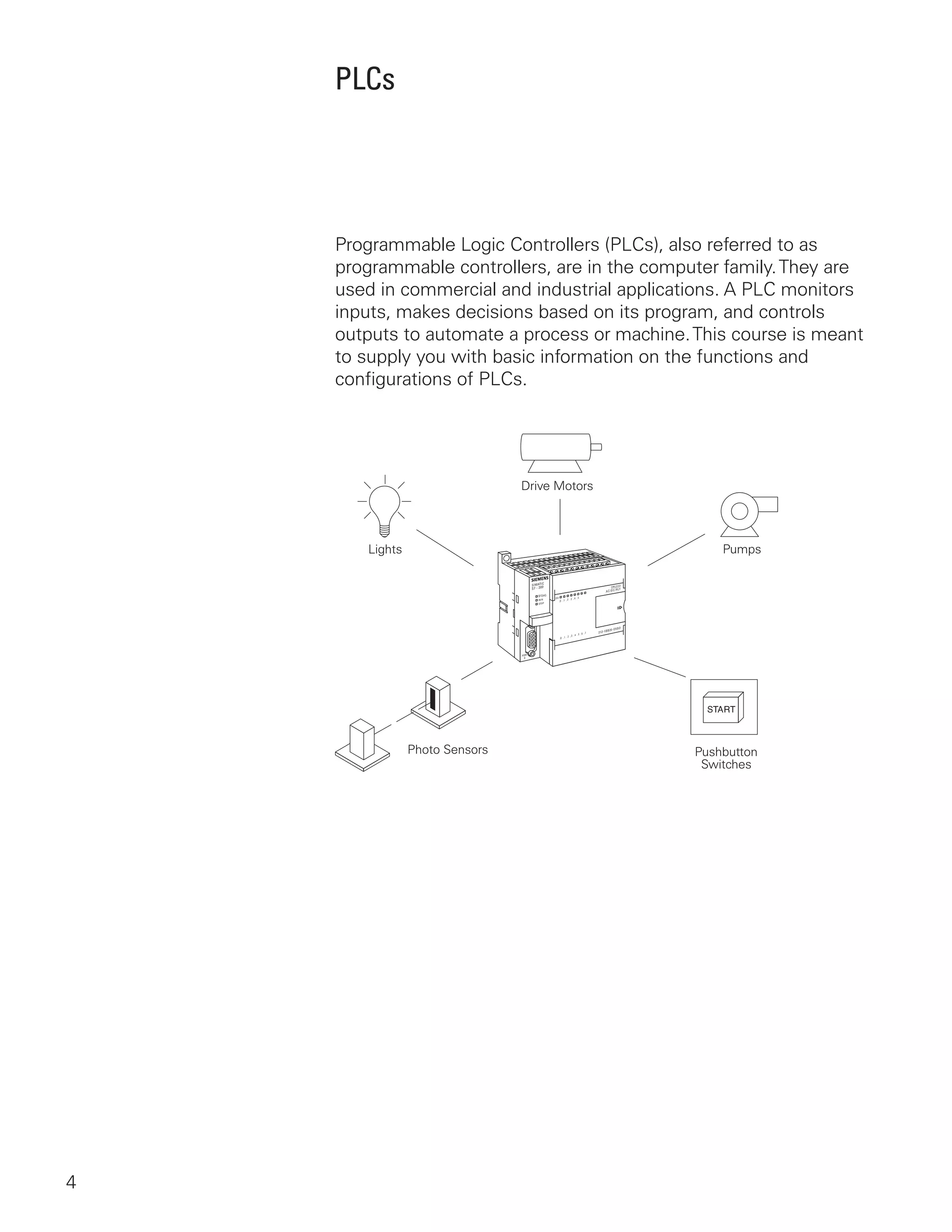
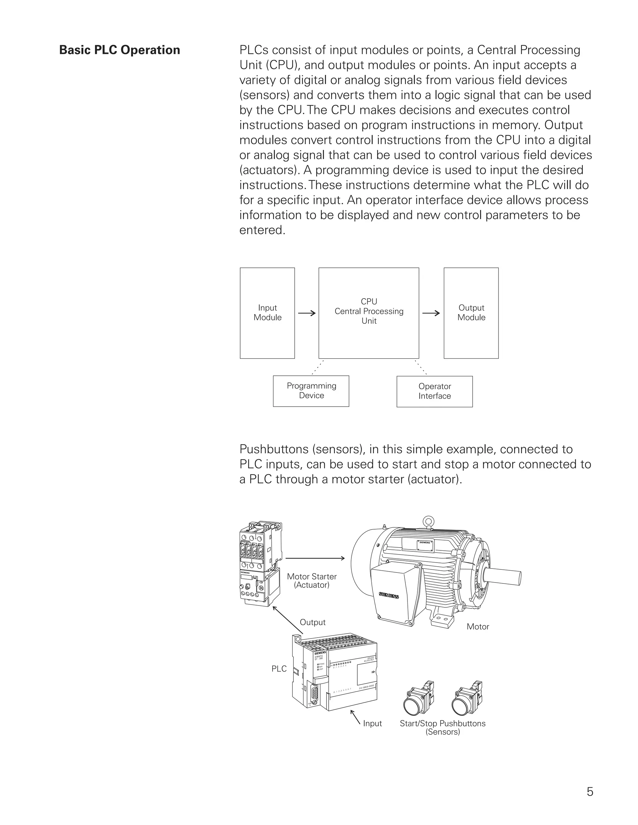
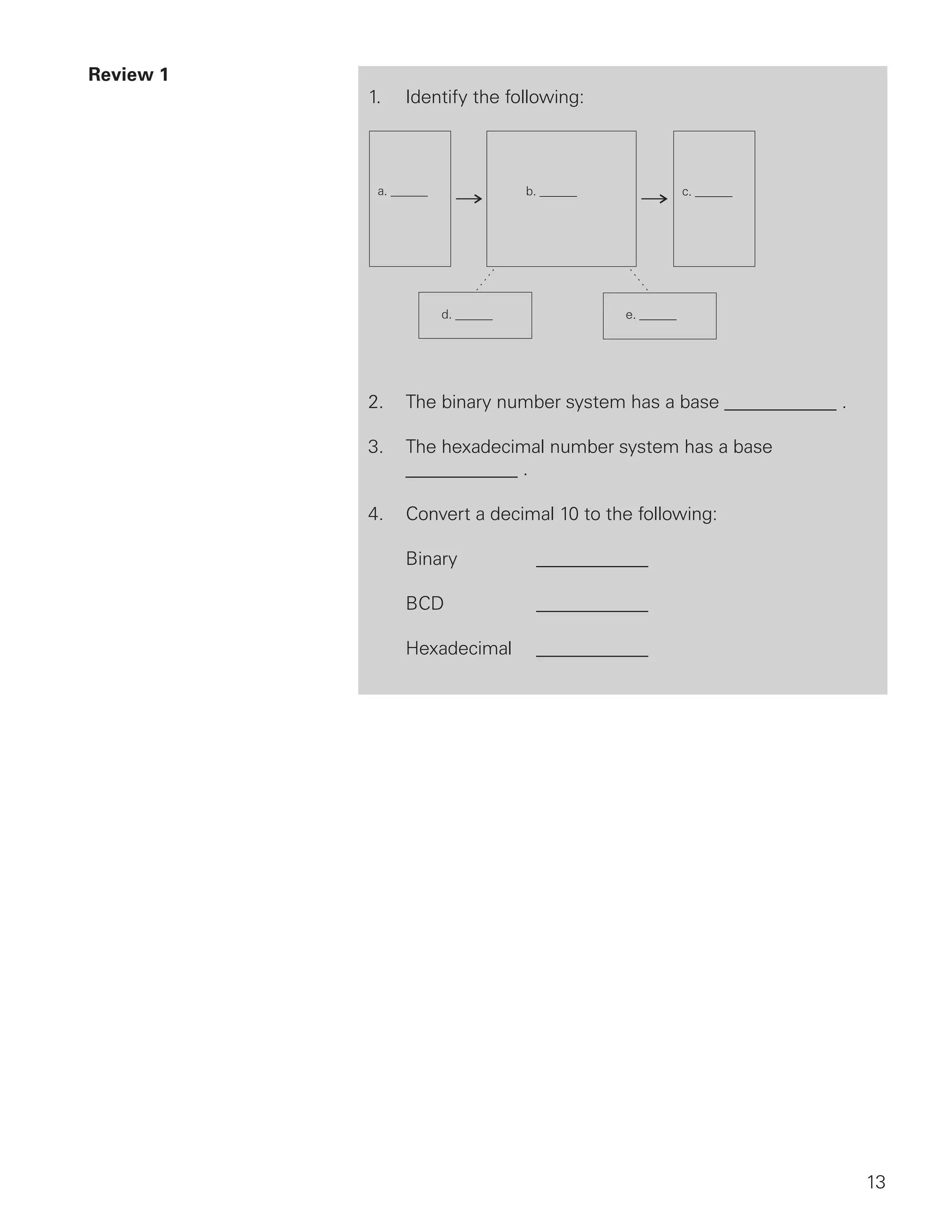
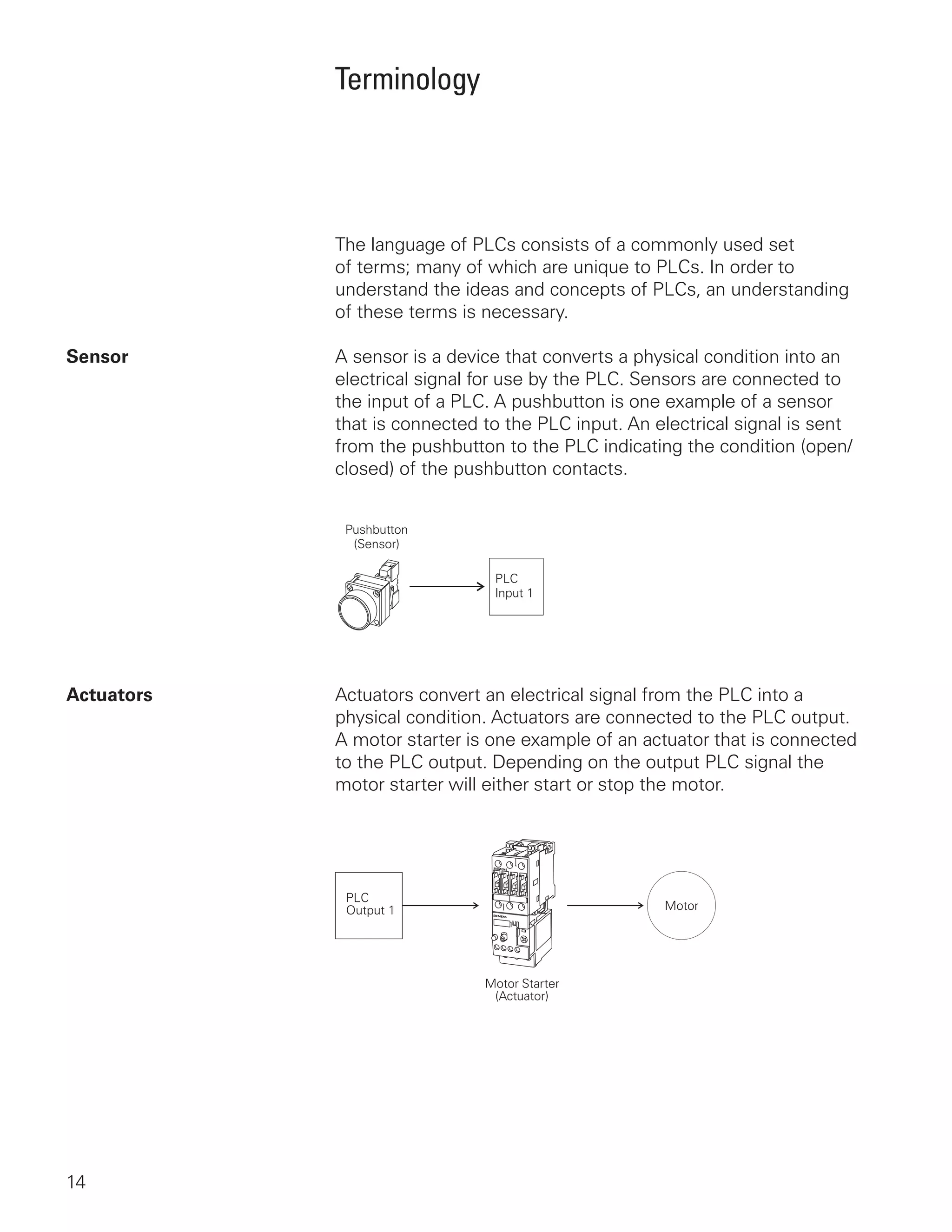
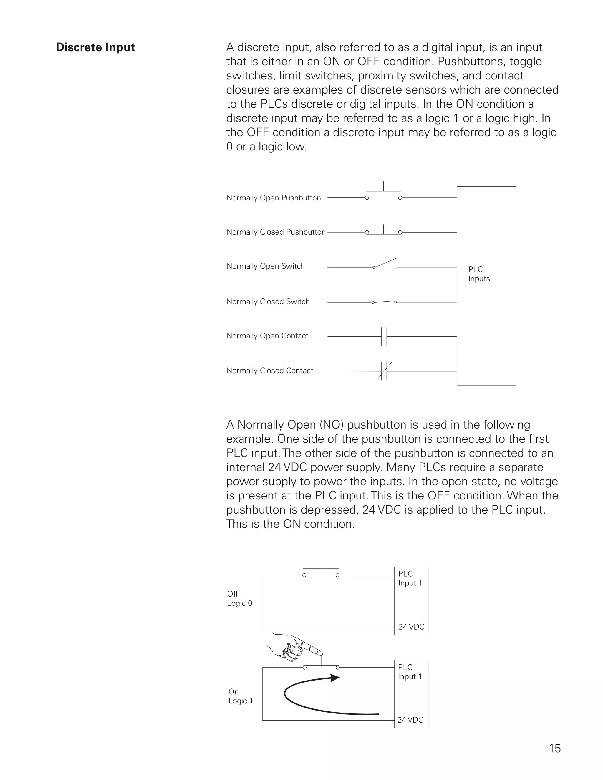
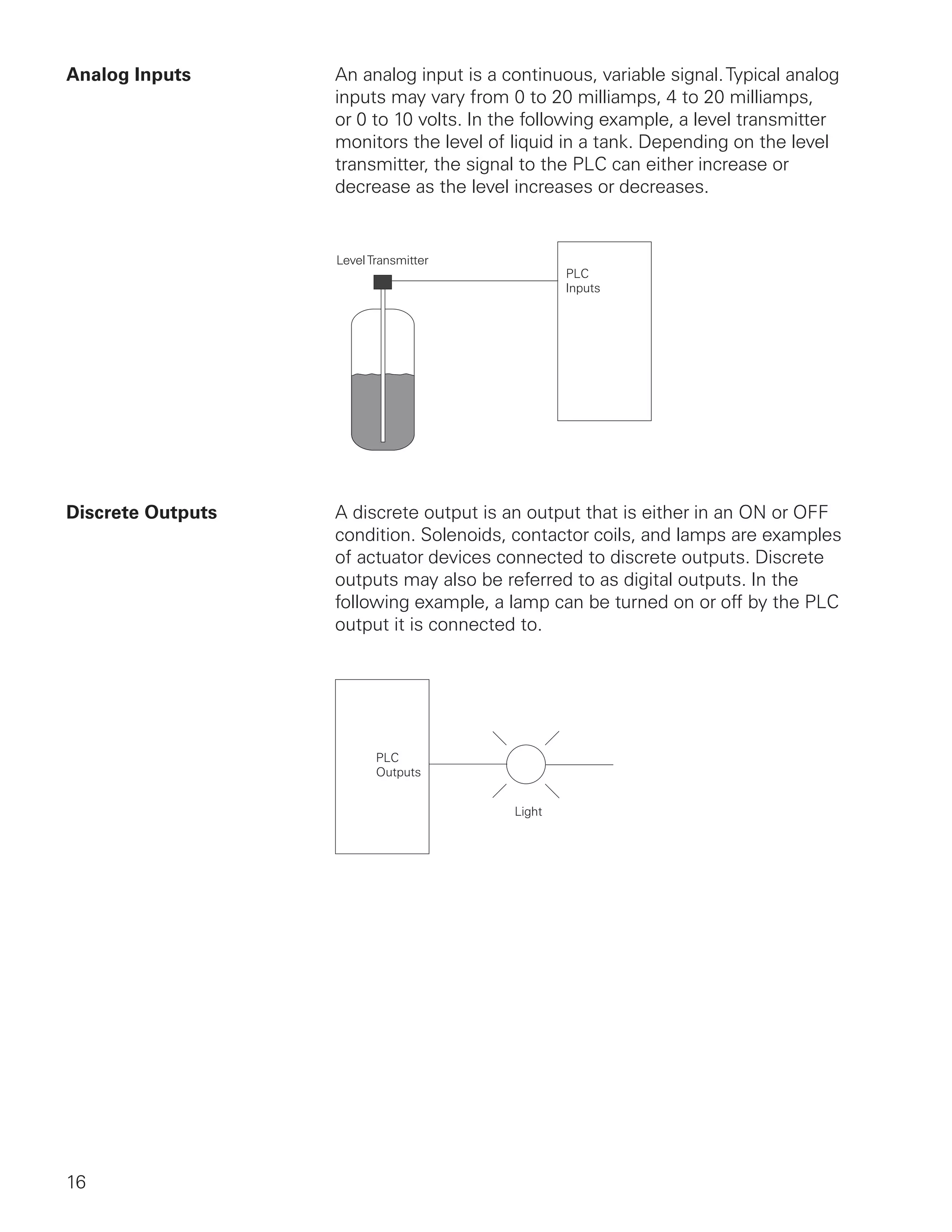

This document provides an overview of programmable logic controllers (PLCs) and related concepts: 1) It describes the basic components and functions of a PLC system including inputs, outputs, the central processing unit (CPU), and how they work together to automate processes. 2) It covers various numeric systems used in PLCs such as binary, decimal, hexadecimal, and BCD. It also defines related terms like bits, bytes, words, logic 0/1. 3) It defines common PLC terminology for sensors, actuators, discrete and analog inputs/outputs, the CPU, and programming methods like ladder logic and statement lists.


![[BDD 2025 - Full-Stack Development] Digital Accessibility: Why Developers nee...](https://cdn.slidesharecdn.com/ss_thumbnails/fs-digitalaccessibilitywhydevelopersneedtoknowandcarein2025-251127011019-0674441d-thumbnail.jpg?width=640&height=640&fit=bounds)


![[BDD 2025 - Artificial Intelligence] Building AI Systems That Users (and Comp...](https://cdn.slidesharecdn.com/ss_thumbnails/ai-buildingaisystemsthatusersandcompanieslove-251124030845-038f7732-thumbnail.jpg?width=640&height=640&fit=bounds)

![[BDD 2025 - Mobile Development] Crafting Immersive UI with E2E and AGSL Shade...](https://cdn.slidesharecdn.com/ss_thumbnails/md-craftingimmersiveuiwithe2eandagslshaderveronicaputrianggraini-251124030840-0c677f44-thumbnail.jpg?width=640&height=640&fit=bounds)


