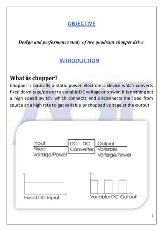
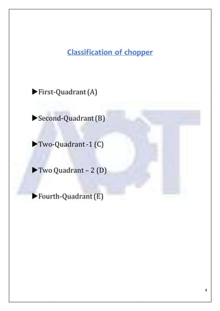
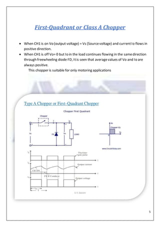
2
CONTENTS
1. Objective and Introduction …3
2. Classification of Chopper …4
3. Types of Chopper …5-8
4. Operations carried out by chopper …9
5. Model Specification …10
6. Voltage Regulator IC 7812 …11
7. LM 3524 PWM …12
8. Absolute Max. Rating …13
9. Performance Characteristics …14
10. Test Circuit …15
11. 2N3055 Transistor with Features …16-17
12. Observations …18-24
13. Advantages and Disadvantages …25-26
14. Applications and Future Scopes …27-28
15. Conclusion …29
16. References …30
3
OBJECTIVE
Design and performance study of two quadrant chopper drive.
INTRODUCTION
What is chopper?
Chopper is basically a static power electronics device which converts
fixed dc voltage/power to variableDC voltageor power. It is nothingbut
a high speed switch which connects and disconnects the load from
source at a high rate to get variable or chopped voltage at the output
4
Classification of chopper
First-Quadrant(A)
Second-Quadrant(B)
Two-Quadrant-1 (C)
Two Quadrant – 2 (D)
Fourth-Quadrant(E)
5
First-Quadrant or Class A Chopper
 When CH1 is on Vo (output voltage) = Vs (Sourcevoltage) and currentIo flows in
positive direction.
 When CH1 is off Vo= 0 but Io in the load continues flowing in the samedirection
through freewheeling diode FD, Itis seen that averagevalues of Vo and Io are
always positive.
This chopper is suitable for only motoring applications
6
Second-Quadrant or Class B Chopper
 When chopper is on, E drivesa currentthrough L and R in oppositeto that
shown in figurebelow. When chopper is off diodeD conducts, and partof
energy stored in inductor L is returned to supply.
7
Two-Quadrant Type A or Class C Chopper
 It is basically a combination of first and second quadrantchoppers.
 In first case CH1 is on and D2 conductswhereasCH2 is on and D1 conductsin
second case.
8
Two-Quadrant Type B or Class D Chopper
 When both CH1 and CH2 are triggered simultaneously, Vo=V and currentflows.
 When both CH1 and CH2 are turned off the load currentcontinues to flow in same
direction through load D1 and D2 due to presenceof inductor L.
9
Operations that are carried out by chopper
 It can step up or step down the voltage (analogous to AC transformer)and hence
are common in Mobile Chargers as well as public transportlike toto.
 Providesregeneration of brake energy.
 ProvidesMotor Speed Control.
 ProvidesVoltage boosting.
 Second-Quadrantchoppersareused in Regenerative brakingof DC motors, two-
quadrantchoppersalong with regeneration providesmotor control
10
MODEL SPECIFICATION
DC MOTOR
APARATUS RATINGS
PERMANENT MAGNET TYPE DC
MOTOR
Voltage 12 V
Current 2 AMPS
Speed 750 rpm
Integrated circuit chips used
Linear Voltage Regulator IC 7812 15 TO 20 V (INPUT VOLTAGE)
12 V (REGULATED OUTPUT
VOLTAGE)
LM 3524 Regulating Pulse Width
Modulator
Supply voltage 40 V
Oscillator charging current 5mA
Output current 200 mA DC
11
Linear Voltage Regulator IC 7812
7812 is a famous IC which is being widely used in 12V voltage regulator
circuits. Truly speaking it is a complete standalone voltage regulator. We
only need to use two capacitors, one on the input and second one on the
output of 7812 in order to achieve clean voltage output and even these
capacitors are optional to use. To achieve 12V 1A current, 7812 should
be mounted on a good heatsink plate. Thanks to the transistor like shape
of 7812 which makes it easy to mount on a heatsink plate. 7812 has built
in over heat and short circuit protection which makes it a good choice for
making power supplies.
12
`LM 3524 Pulse Width Modulator
The LM3524 regulating pulse-width-modulator (PWM) is commonly used as the
control element in switching regulator power supplies. The LM3524D has a ±1%
precision5V reference.The current carrying capability of the output drive2 transistors
has beenraised to 200 mA while reducing VCEsatand increasing VCE breakdown to
60V. The common mode voltage range of the error-amp has been raised to 5.5V to
eliminate the need for a resistive divider from the 5V reference.
1FEATURES
2• Fully Interchangeable With
Standard LM3524 Family
• ±1% Precision 5V Reference
With Thermal Shut-Down
• Output Current to 200 mA DC.
• 60V Output Capability
• Wide Common Mode Input
Range for Error Amp
• One Pulse per Period
(Noise Suppression)
• Improved Max. Duty Cycle
at High Frequencies
• Synchronize Through Pin 3
13
Absolute Maximum Ratings
 Absolute maximum ratings indicate limits beyond which damage to the
device may occur. DC and AC electrical specifications do not apply when
operating the device beyond its rated operating conditions.
14
Typical Performance Characteristics
15
TEST CIRCUIT
16
2N3055 Transistor
The 2N3055 is a NPN Epitaxial-Base Planar Transistor
that normally comes encapsulated in a metal Jedec TO-3
package. The basic application range include
power switching, high fidelity amplification,
shunt regulation, and forming the output stages
of various power circuits.
.
Almost90 % of all medium power electronic
gadgets incorporate 2N3055 transistors in their
output stages – probably enough to prove the high versatility of the device. The
article provides you with all the necessarydetails about this important electronic
active component.
17
Features of 2N3055 Transistor
1. High collectorto emitter voltage handling capability makes it highly
versatile for mostpower amplification applications
2. Low base to emitter voltage, makes it easily switchable even with nominal
output potentials available from linear ICs without incorporating buffer
stages.
3. High frequencyhandling range, again attributing the device with a wide
range utility feature .Robust output current delivering capability makes it
ideally suited for applications in power amplifiers and power inverters.
4. The above versatility of the device in turn makes it easily replaceable with
other power transistors having varied characteristics, relieving the users
from the headache of searching identical compatible matches for their
individual specific applications.
Internal Structure of 2N3055 Transistor
18
OBSERVATIONS
Circuit Diagram
 Observed Voltage Magnitudes:
AC Voltage(Vac) 14.8V
DC Voltage(Vdc) 17.00V
Base Voltage(Vbase) 11.94V
Collector Voltage(Vcollector) 16.32V
Emmiter Voltage(Vemitter) 11.32V
Voltage across
motor(Vmotor)
11.25V
19
 Waveforms:
Calculation of Duty Cycle of above waveforms:
Dmax = (Ton / T) * 100 = (1 / 1.6) * 100 = 62.5% (for 1st
waveform)
Dmin = (Ton / T) * 100 = (0.3 / 1.6) * 100 = 18.75% (for 2nd
waveform)
20
Table:
Variation in speed with Armature voltage
Graphs for above parameters:-
Voltage(Va)
(volt)
Speed
(rpm)
Duty
Cycle(D)
1. 2.9 78 18.75
2. 3.92 106 25
3. 5.12 142 31.25
4. 5.9 163 37.5
5. 7.1 195.8 43.75
50
100
150
200
250
Speedinrpm
Voltage(Va) vs Speed(rpm)
21
0
1
2
3
4
5
6
7
8
0 5 10 15 20 25 30 35 40 45 50
VoltageinVolt
Duty Cycle
Duty Cycle vs Voltage(Va)
22
The Waveforms for above given values:-
Time
Amplitude
Waveform for 2.9V
Duty Cycle=18.75
0
50
100
150
200
250
0 5 10 15 20 25 30 35 40 45 50
Speedinrpm
Duty Cycle
Duty Cycle vs Speed(rpm)
23
Amplitude
Time
Time
Amplitude
Waveform for 3.92V
Waveform for 5.12V
Duty Cycle=25
Duty Cycle=31.25
24
Amplitude
Time
Waveform for 5.9V
Waveform for 7.1V
Amplitude
Duty Cycle=37.5
25
ADVANTAGES
 Both forward motoring as well as forward braking is possible, which
can use either regenerative or dynamic mode of braking.
Time
Duty Cycle=43.75
26
 Chopper circuit is simple and can be modified to provide regeneration
and the control is also simple.
 Lower cost, reliability and simple control for variable speed
application.
 Regenerative braking can be carried out up to very low speeds even
when the drive is fed from a fixed voltage dc source.
 Peak/average and RMS/average current ratio are small.
 Current drawn by chopper is smaller than in phase controlled
converters. Good speed regulation and frequent starting, braking and
reversing
DISADVANTAGES
27
Source current of a chopper fed drive consists of pulses which are
rich in harmonics and can also cause fluctuations in supply voltage.
Usually the L-C input filter is provided to reduce harmonics and
eliminate voltage fluctuations.
 For the same rating the size of DC drive is much bigger than the AC
drives.
 DC drives require more maintenance.
 Overall operating cost is high compared to AC drives.
APPLICATIONS
28
 Battery operated vehicle.
 Traction motor control in electric traction.
 Trolley Cars
 Hoists.
 Electric braking
29
FUTURE SCOPE
Hybrid cars and Electric Vehicles are the most promising
concepts in the upcoming years due to the inadequate
availability of fossil fuels and the high level of pollution
caused by them.
So looking forward to the future these Electric Vehicles
can be an alternative to the present generation combustion
engine cars.
30
CONCLUSION
The two quadrant operation of dc drive include the forward motoring
mode in 1st
quadrant where the voltage and current both are positive and
forward braking mode in 2nd
quadrant where voltage is positive and the
current is negative. Since we are using two quadrant choppers so
regenerative braking can be carried out up to very low speeds even
when the drive is fed from a fixed voltage dc source. Using thyristor
(SCR) as switch requires extra commutation circuit whereas IGBT,
MOSFET does not require any commutation circuit and can work on
small pulsating signals the IGBT’s are used for high power operation
and the MOSFET’s are used for low power operation. Controlling the
pulses across these semi-conductor devices we can control the speed of
the drive.
31
REFERENCES
1. International Journal of Engineering Research and Technology
(IJERT), Vol 3 Issue 2, ISSN: 2278-0181.
2. www.ti.com, SNVS766E-June 2009, Revised May 2013.
3. Wester, G. W. & Middlebrook, R. D. “Low- Frequency
Characterization of Switched dc-dc Converters”, IEEE
Transactions on Aerospace and Electronic Systems, vol.AES-9,n.3,
pp.376-385, 1973.
4. Gopal, M control system, principles and design. New Delhi, Tata
McGraw Hill Publishing Company limited, 2008.
5. Mohan, Ned, Electrical Drives an Integrated approach.
6. MATLAB and SIMULINK Version 2015.

Two Quadrant chopper

  • 1.
    2 CONTENTS 1. Objective andIntroduction …3 2. Classification of Chopper …4 3. Types of Chopper …5-8 4. Operations carried out by chopper …9 5. Model Specification …10 6. Voltage Regulator IC 7812 …11 7. LM 3524 PWM …12 8. Absolute Max. Rating …13 9. Performance Characteristics …14 10. Test Circuit …15 11. 2N3055 Transistor with Features …16-17 12. Observations …18-24 13. Advantages and Disadvantages …25-26 14. Applications and Future Scopes …27-28 15. Conclusion …29 16. References …30
  • 2.
    3 OBJECTIVE Design and performancestudy of two quadrant chopper drive. INTRODUCTION What is chopper? Chopper is basically a static power electronics device which converts fixed dc voltage/power to variableDC voltageor power. It is nothingbut a high speed switch which connects and disconnects the load from source at a high rate to get variable or chopped voltage at the output
  • 3.
  • 4.
    5 First-Quadrant or ClassA Chopper  When CH1 is on Vo (output voltage) = Vs (Sourcevoltage) and currentIo flows in positive direction.  When CH1 is off Vo= 0 but Io in the load continues flowing in the samedirection through freewheeling diode FD, Itis seen that averagevalues of Vo and Io are always positive. This chopper is suitable for only motoring applications
  • 5.
    6 Second-Quadrant or ClassB Chopper  When chopper is on, E drivesa currentthrough L and R in oppositeto that shown in figurebelow. When chopper is off diodeD conducts, and partof energy stored in inductor L is returned to supply.
  • 6.
    7 Two-Quadrant Type Aor Class C Chopper  It is basically a combination of first and second quadrantchoppers.  In first case CH1 is on and D2 conductswhereasCH2 is on and D1 conductsin second case.
  • 7.
    8 Two-Quadrant Type Bor Class D Chopper  When both CH1 and CH2 are triggered simultaneously, Vo=V and currentflows.  When both CH1 and CH2 are turned off the load currentcontinues to flow in same direction through load D1 and D2 due to presenceof inductor L.
  • 8.
    9 Operations that arecarried out by chopper  It can step up or step down the voltage (analogous to AC transformer)and hence are common in Mobile Chargers as well as public transportlike toto.  Providesregeneration of brake energy.  ProvidesMotor Speed Control.  ProvidesVoltage boosting.  Second-Quadrantchoppersareused in Regenerative brakingof DC motors, two- quadrantchoppersalong with regeneration providesmotor control
  • 9.
    10 MODEL SPECIFICATION DC MOTOR APARATUSRATINGS PERMANENT MAGNET TYPE DC MOTOR Voltage 12 V Current 2 AMPS Speed 750 rpm Integrated circuit chips used Linear Voltage Regulator IC 7812 15 TO 20 V (INPUT VOLTAGE) 12 V (REGULATED OUTPUT VOLTAGE) LM 3524 Regulating Pulse Width Modulator Supply voltage 40 V Oscillator charging current 5mA Output current 200 mA DC
  • 10.
    11 Linear Voltage RegulatorIC 7812 7812 is a famous IC which is being widely used in 12V voltage regulator circuits. Truly speaking it is a complete standalone voltage regulator. We only need to use two capacitors, one on the input and second one on the output of 7812 in order to achieve clean voltage output and even these capacitors are optional to use. To achieve 12V 1A current, 7812 should be mounted on a good heatsink plate. Thanks to the transistor like shape of 7812 which makes it easy to mount on a heatsink plate. 7812 has built in over heat and short circuit protection which makes it a good choice for making power supplies.
  • 11.
    12 `LM 3524 PulseWidth Modulator The LM3524 regulating pulse-width-modulator (PWM) is commonly used as the control element in switching regulator power supplies. The LM3524D has a ±1% precision5V reference.The current carrying capability of the output drive2 transistors has beenraised to 200 mA while reducing VCEsatand increasing VCE breakdown to 60V. The common mode voltage range of the error-amp has been raised to 5.5V to eliminate the need for a resistive divider from the 5V reference. 1FEATURES 2• Fully Interchangeable With Standard LM3524 Family • ±1% Precision 5V Reference With Thermal Shut-Down • Output Current to 200 mA DC. • 60V Output Capability • Wide Common Mode Input Range for Error Amp • One Pulse per Period (Noise Suppression) • Improved Max. Duty Cycle at High Frequencies • Synchronize Through Pin 3
  • 12.
    13 Absolute Maximum Ratings Absolute maximum ratings indicate limits beyond which damage to the device may occur. DC and AC electrical specifications do not apply when operating the device beyond its rated operating conditions.
  • 13.
  • 14.
  • 15.
    16 2N3055 Transistor The 2N3055is a NPN Epitaxial-Base Planar Transistor that normally comes encapsulated in a metal Jedec TO-3 package. The basic application range include power switching, high fidelity amplification, shunt regulation, and forming the output stages of various power circuits. . Almost90 % of all medium power electronic gadgets incorporate 2N3055 transistors in their output stages – probably enough to prove the high versatility of the device. The article provides you with all the necessarydetails about this important electronic active component.
  • 16.
    17 Features of 2N3055Transistor 1. High collectorto emitter voltage handling capability makes it highly versatile for mostpower amplification applications 2. Low base to emitter voltage, makes it easily switchable even with nominal output potentials available from linear ICs without incorporating buffer stages. 3. High frequencyhandling range, again attributing the device with a wide range utility feature .Robust output current delivering capability makes it ideally suited for applications in power amplifiers and power inverters. 4. The above versatility of the device in turn makes it easily replaceable with other power transistors having varied characteristics, relieving the users from the headache of searching identical compatible matches for their individual specific applications. Internal Structure of 2N3055 Transistor
  • 17.
    18 OBSERVATIONS Circuit Diagram  ObservedVoltage Magnitudes: AC Voltage(Vac) 14.8V DC Voltage(Vdc) 17.00V Base Voltage(Vbase) 11.94V Collector Voltage(Vcollector) 16.32V Emmiter Voltage(Vemitter) 11.32V Voltage across motor(Vmotor) 11.25V
  • 18.
    19  Waveforms: Calculation ofDuty Cycle of above waveforms: Dmax = (Ton / T) * 100 = (1 / 1.6) * 100 = 62.5% (for 1st waveform) Dmin = (Ton / T) * 100 = (0.3 / 1.6) * 100 = 18.75% (for 2nd waveform)
  • 19.
    20 Table: Variation in speedwith Armature voltage Graphs for above parameters:- Voltage(Va) (volt) Speed (rpm) Duty Cycle(D) 1. 2.9 78 18.75 2. 3.92 106 25 3. 5.12 142 31.25 4. 5.9 163 37.5 5. 7.1 195.8 43.75 50 100 150 200 250 Speedinrpm Voltage(Va) vs Speed(rpm)
  • 20.
    21 0 1 2 3 4 5 6 7 8 0 5 1015 20 25 30 35 40 45 50 VoltageinVolt Duty Cycle Duty Cycle vs Voltage(Va)
  • 21.
    22 The Waveforms forabove given values:- Time Amplitude Waveform for 2.9V Duty Cycle=18.75 0 50 100 150 200 250 0 5 10 15 20 25 30 35 40 45 50 Speedinrpm Duty Cycle Duty Cycle vs Speed(rpm)
  • 22.
    23 Amplitude Time Time Amplitude Waveform for 3.92V Waveformfor 5.12V Duty Cycle=25 Duty Cycle=31.25
  • 23.
    24 Amplitude Time Waveform for 5.9V Waveformfor 7.1V Amplitude Duty Cycle=37.5
  • 24.
    25 ADVANTAGES  Both forwardmotoring as well as forward braking is possible, which can use either regenerative or dynamic mode of braking. Time Duty Cycle=43.75
  • 25.
    26  Chopper circuitis simple and can be modified to provide regeneration and the control is also simple.  Lower cost, reliability and simple control for variable speed application.  Regenerative braking can be carried out up to very low speeds even when the drive is fed from a fixed voltage dc source.  Peak/average and RMS/average current ratio are small.  Current drawn by chopper is smaller than in phase controlled converters. Good speed regulation and frequent starting, braking and reversing DISADVANTAGES
  • 26.
    27 Source current ofa chopper fed drive consists of pulses which are rich in harmonics and can also cause fluctuations in supply voltage. Usually the L-C input filter is provided to reduce harmonics and eliminate voltage fluctuations.  For the same rating the size of DC drive is much bigger than the AC drives.  DC drives require more maintenance.  Overall operating cost is high compared to AC drives. APPLICATIONS
  • 27.
    28  Battery operatedvehicle.  Traction motor control in electric traction.  Trolley Cars  Hoists.  Electric braking
  • 28.
    29 FUTURE SCOPE Hybrid carsand Electric Vehicles are the most promising concepts in the upcoming years due to the inadequate availability of fossil fuels and the high level of pollution caused by them. So looking forward to the future these Electric Vehicles can be an alternative to the present generation combustion engine cars.
  • 29.
    30 CONCLUSION The two quadrantoperation of dc drive include the forward motoring mode in 1st quadrant where the voltage and current both are positive and forward braking mode in 2nd quadrant where voltage is positive and the current is negative. Since we are using two quadrant choppers so regenerative braking can be carried out up to very low speeds even when the drive is fed from a fixed voltage dc source. Using thyristor (SCR) as switch requires extra commutation circuit whereas IGBT, MOSFET does not require any commutation circuit and can work on small pulsating signals the IGBT’s are used for high power operation and the MOSFET’s are used for low power operation. Controlling the pulses across these semi-conductor devices we can control the speed of the drive.
  • 30.
    31 REFERENCES 1. International Journalof Engineering Research and Technology (IJERT), Vol 3 Issue 2, ISSN: 2278-0181. 2. www.ti.com, SNVS766E-June 2009, Revised May 2013. 3. Wester, G. W. & Middlebrook, R. D. “Low- Frequency Characterization of Switched dc-dc Converters”, IEEE Transactions on Aerospace and Electronic Systems, vol.AES-9,n.3, pp.376-385, 1973. 4. Gopal, M control system, principles and design. New Delhi, Tata McGraw Hill Publishing Company limited, 2008. 5. Mohan, Ned, Electrical Drives an Integrated approach. 6. MATLAB and SIMULINK Version 2015.