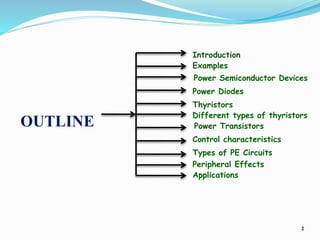
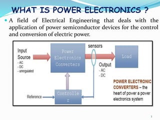
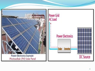
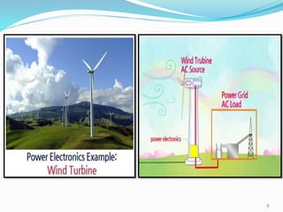
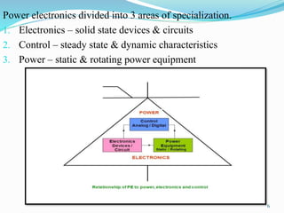
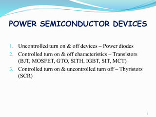
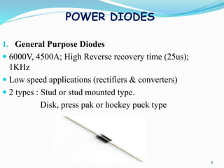
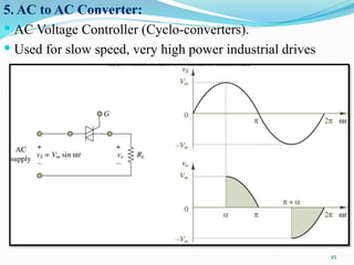
POWER ELECTRONICS – 10EC73
1
Presented by,
Ms. Sangeetha B L
OUTLINE
2
Introduction
Thyristors
Power Transistors
Power Semiconductor Devices
Different types of thyristors
Applications
Types of PE Circuits
Power Diodes
Control characteristics
Peripheral Effects
Examples
WHAT IS POWER ELECTRONICS ?
 A field of Electrical Engineering that deals with the
application of power semiconductor devices for the control
and conversion of electric power.
3
4
5
Power electronics divided into 3 areas of specialization.
1. Electronics – solid state devices & circuits
2. Control – steady state & dynamic characteristics
3. Power – static & rotating power equipment
6
POWER SEMICONDUCTOR DEVICES
1. Uncontrolled turn on & off devices – Power diodes
2. Controlled turn on & off characteristics – Transistors
(BJT, MOSFET, GTO, SITH, IGBT, SIT, MCT)
3. Controlled turn on & uncontrolled turn off – Thyristors
(SCR)
7
POWER DIODES
1. General Purpose Diodes
 6000V, 4500A; High Reverse recovery time (25us);
1KHz
 Low speed applications (rectifiers & converters)
 2 types : Stud or stud mounted type.
Disk, press pak or hockey puck type
8
2. High speed:
 Fast recovery diodes
 6000V, 1100A;
 Reverse recovery times varies between 0.1 & 5us
 High frequency switching of power converters
 Used in low speed applications (choppers & inverters)
9
3. Schottky Diodes:
 Low on state voltage and very small recovery time (ns)
 100V, 300A;
 Pn junction is eliminated
 Metal is anode & semiconductor is cathode.
 Have high switching frequencies.
 Drift layer is absent; On – state losses are very low.
 Low voltage converters as feedback & freewheeling diodes.
10
STRUCTURE OF POWER DIODE
+
V
-
Anode
Cathode
Na =10 cm
19 -3
P
+
Nd =10 cm
-3
Nd =10 cm
19 -3
-314
n+
-
n
epi
substrate
10μm
250μm
Breakdown
Voltage dependent
11
I – V CHARACTERISTICS
12
SWITCHING CHARACTERISTICS
13
APPLICATIONS OF PD
 Uncontrolled rectifiers
 Choppers, inverters & controlled converters
 Commutating circuits for SCRs
 Half controlled converters & half bridge inverters.
14
THYRISTORS
 Turn on – control signal
 Turn off – power circuit
 Controllable switches are turned on & turned off – controlled
signals.
 Line & Forced Commutated Thyristor
1. SCR
2. GTO
3. RCT
4. SITH
5. GATT
6. LASCR
7. MTO
8. ETO
9. IGCT
10. MCT
15
SILICON CONTROLLED RECTIFIER
 SCR turns off whenever the current falls to zero or by
making the potential of the anode equal to or less than
the cathode potential.
16
V – I CHARACTERISTICS
17
MERITS
 Very small amount of gate drive is required.
 On state losses are reduced
DEMERITS
 Gate has no control once SCR is turned on
 External circuits are required to turn off
APPLICATIONS
 Used for high power low frequency applications
 Controlled rectifiers
 AC regulators, lighting and heating applications
 DC motor drives, large power supplies & electric circuit breakers
18
GATE TURN – OFF THYRISTORS
19
 GTO do not require commutation circuit
 Used for forced commutation of converters & 6000V,
6000A.
 Used for Low power applications
 Eliminates the need for forced commutation circuitry
& hence reduces cost
 Gate drive required to turn off is very large
 More power
20
STATIC INDUCTION THYRISTOR
• Used in medium power converter
circuits with frequency of several
hundred KHz .
• 1200V, 300A
• Turn off gain is very high
• 4500V, 250A
•Low power ratings than GTO &
SITH
MOS-CONTROLLED
THYRISTOR
21
LIGHT ACTIVATED SCR
 Turned on by light
signal
 Gate is photosensitive
 Isolation
 6000V, 1500A;
switching speed of
200-400us
 High voltage power
systems (HVDC)
22
REVERSE CONDUCTING THYRISTORS
 Inverse parallel diode. (Anti-
parallel)
 4000V, 2000A & 800A in reverse
conduction
 Switching time 40us
 High speed switching in traction
applications
 Suitable for induction loads
23
GATE ASSISTED TURN OFF
THYRISTOR – GATT
 Used for high speed switching, medium power
applications
 They require forced turn – off circuits
 1200V, 400A with switching speed of 8us
24
TRIAC – BIDIRECTIONAL TRIODE
THYRISTOR
 Low power AC applications
 Heat controls, light controls,
motor controls & AC switches.
 Current flow can be controlled
in either direction.
 Turned off by line
commutation of the AC supply
25
MOS TURN-OFF (MTO) THYRISTOR
26
 It is a combination of a
GTO & MOSFET.
 High voltage (upto 10KV)
& high current (upto
4000A)
 High power applications
EMITTER TURN OFF THYRISTOR
27
 It is a MOS-GTO hybrid device
that combines the advantage of
both the GTO & MOSFET.
 2 gates : One normal gate for turn
on & one with a series MOSFET
for turn off.
 Current rating upto 4KA & voltage
rating upto 6KV.
IGCT
28
 It integrates a GCT with a
multilayered PCB gate
drive.
 Turned on by applying the
turn on current to its gate
 Turned off by a
multilayered gate driver
PCB.
 Used in current fed inverter
drives
POWER TRANSISTOR:
BIPOLAR JUNCTION TRANSISTOR
29
Used in power converters (>10KHz)
POWER MOSFET
30
•Used in high speed power converters.
•Low power SMPS & Inverters
IGBT
31
Used in PWM inverters & SMPS
STATIC INDUCTION
TRANSISTOR
32
 High power, high frequency
device
 Low noise, low distortion,
high audio frequency power
capability
 Suitable for low power, high
frequency application &
microwave amplifiers
CONTROL CHARACTERISTICS
1. SCR
33
2. GTO/SITH/MTO/ETO/IGCT
34
3. BJT
35
4. MOSFET & IGBT
36
Classification of power semiconductor devices
1. Uncontrolled turn on and off (Power Diode)
2. Controlled turn on uncontrolled turn off (Thyristors)
3. Controlled turn on and off characteristic (Power Transistor, BJT,
MOSFET, GTO, IGBT)
4. Continuous gate signal requirement (BJT, MOSFET, IGBT, SIT)
5. Pulse gate requirement (SCR, GTO, MCT)
6. Bipolar voltage-withstanding capability (SCR, GTO)
7. Unipolar voltage-withstanding capability (BJT, MOSFET, GTO,
IGBT, MCT)
8. Bidirectional current capability (TRIAC, RCT)
9. Undirectional current capability (SCR, GTO, BJT, MOSFET, IGBT,
MCT, Diode)
37
TYPES OF PE CIRCUITS
1. Diode Rectifiers: Converts ac voltage into fixed dc
voltage.
Input voltage to the rectifier Vi could be either
single phase or three phase
38
2. AC to DC Converter :
 Phase controlled Rectifier.
39
• Use line voltage
for commutation
•HVDC
•DC Motor drives
•Static VAR
compensators
•UPS
Battery charger : AC – DC Converter
40
3. DC to AC Converter: Inverters.
 Used when main is not available, Low power portable
electronic system
 UPS, aircraft & space PS, HVDC etc.,
41
Electric drive unit : DC – AC convertor
42
Example: Renewable Power Generation (PV)
PV Inverter: DC-AC Converter
43
4. DC to DC Converter:
 Chopper in case of High power & SMPS in case of small
Power Rating.
44
5. AC to AC Converter:
 AC Voltage Controller (Cyclo-converters).
 Used for slow speed, very high power industrial drives
45
Example: Renewable Power Generation (Wind)
46
6. Static Switches:
 Supply to these switches can be ac or dc.
 Ac static switches or dc switches
 Number of conversion stages are cascaded to produce the
desired output
47
PERIFERAL EFFECTS
 Power converter uses switches to convert input power in
required form.
1. Switching voltage or current pulses are induced in the
power supply
2. Harmonics are induced in power supply due to improper
waveforms.
3. Load contains voltage or current spikes and harmonics
4. Interference is radiated (RFI & EMI) due to switching of
devices.
48
49

Power Electronics-Introduction

  • 1.
    POWER ELECTRONICS –10EC73 1 Presented by, Ms. Sangeetha B L
  • 2.
    OUTLINE 2 Introduction Thyristors Power Transistors Power SemiconductorDevices Different types of thyristors Applications Types of PE Circuits Power Diodes Control characteristics Peripheral Effects Examples
  • 3.
    WHAT IS POWERELECTRONICS ?  A field of Electrical Engineering that deals with the application of power semiconductor devices for the control and conversion of electric power. 3
  • 4.
  • 5.
  • 6.
    Power electronics dividedinto 3 areas of specialization. 1. Electronics – solid state devices & circuits 2. Control – steady state & dynamic characteristics 3. Power – static & rotating power equipment 6
  • 7.
    POWER SEMICONDUCTOR DEVICES 1.Uncontrolled turn on & off devices – Power diodes 2. Controlled turn on & off characteristics – Transistors (BJT, MOSFET, GTO, SITH, IGBT, SIT, MCT) 3. Controlled turn on & uncontrolled turn off – Thyristors (SCR) 7
  • 8.
    POWER DIODES 1. GeneralPurpose Diodes  6000V, 4500A; High Reverse recovery time (25us); 1KHz  Low speed applications (rectifiers & converters)  2 types : Stud or stud mounted type. Disk, press pak or hockey puck type 8
  • 9.
    2. High speed: Fast recovery diodes  6000V, 1100A;  Reverse recovery times varies between 0.1 & 5us  High frequency switching of power converters  Used in low speed applications (choppers & inverters) 9
  • 10.
    3. Schottky Diodes: Low on state voltage and very small recovery time (ns)  100V, 300A;  Pn junction is eliminated  Metal is anode & semiconductor is cathode.  Have high switching frequencies.  Drift layer is absent; On – state losses are very low.  Low voltage converters as feedback & freewheeling diodes. 10
  • 11.
    STRUCTURE OF POWERDIODE + V - Anode Cathode Na =10 cm 19 -3 P + Nd =10 cm -3 Nd =10 cm 19 -3 -314 n+ - n epi substrate 10μm 250μm Breakdown Voltage dependent 11
  • 12.
    I – VCHARACTERISTICS 12
  • 13.
  • 14.
    APPLICATIONS OF PD Uncontrolled rectifiers  Choppers, inverters & controlled converters  Commutating circuits for SCRs  Half controlled converters & half bridge inverters. 14
  • 15.
    THYRISTORS  Turn on– control signal  Turn off – power circuit  Controllable switches are turned on & turned off – controlled signals.  Line & Forced Commutated Thyristor 1. SCR 2. GTO 3. RCT 4. SITH 5. GATT 6. LASCR 7. MTO 8. ETO 9. IGCT 10. MCT 15
  • 16.
    SILICON CONTROLLED RECTIFIER SCR turns off whenever the current falls to zero or by making the potential of the anode equal to or less than the cathode potential. 16
  • 17.
    V – ICHARACTERISTICS 17
  • 18.
    MERITS  Very smallamount of gate drive is required.  On state losses are reduced DEMERITS  Gate has no control once SCR is turned on  External circuits are required to turn off APPLICATIONS  Used for high power low frequency applications  Controlled rectifiers  AC regulators, lighting and heating applications  DC motor drives, large power supplies & electric circuit breakers 18
  • 19.
    GATE TURN –OFF THYRISTORS 19
  • 20.
     GTO donot require commutation circuit  Used for forced commutation of converters & 6000V, 6000A.  Used for Low power applications  Eliminates the need for forced commutation circuitry & hence reduces cost  Gate drive required to turn off is very large  More power 20
  • 21.
    STATIC INDUCTION THYRISTOR •Used in medium power converter circuits with frequency of several hundred KHz . • 1200V, 300A • Turn off gain is very high • 4500V, 250A •Low power ratings than GTO & SITH MOS-CONTROLLED THYRISTOR 21
  • 22.
    LIGHT ACTIVATED SCR Turned on by light signal  Gate is photosensitive  Isolation  6000V, 1500A; switching speed of 200-400us  High voltage power systems (HVDC) 22
  • 23.
    REVERSE CONDUCTING THYRISTORS Inverse parallel diode. (Anti- parallel)  4000V, 2000A & 800A in reverse conduction  Switching time 40us  High speed switching in traction applications  Suitable for induction loads 23
  • 24.
    GATE ASSISTED TURNOFF THYRISTOR – GATT  Used for high speed switching, medium power applications  They require forced turn – off circuits  1200V, 400A with switching speed of 8us 24
  • 25.
    TRIAC – BIDIRECTIONALTRIODE THYRISTOR  Low power AC applications  Heat controls, light controls, motor controls & AC switches.  Current flow can be controlled in either direction.  Turned off by line commutation of the AC supply 25
  • 26.
    MOS TURN-OFF (MTO)THYRISTOR 26  It is a combination of a GTO & MOSFET.  High voltage (upto 10KV) & high current (upto 4000A)  High power applications
  • 27.
    EMITTER TURN OFFTHYRISTOR 27  It is a MOS-GTO hybrid device that combines the advantage of both the GTO & MOSFET.  2 gates : One normal gate for turn on & one with a series MOSFET for turn off.  Current rating upto 4KA & voltage rating upto 6KV.
  • 28.
    IGCT 28  It integratesa GCT with a multilayered PCB gate drive.  Turned on by applying the turn on current to its gate  Turned off by a multilayered gate driver PCB.  Used in current fed inverter drives
  • 29.
    POWER TRANSISTOR: BIPOLAR JUNCTIONTRANSISTOR 29 Used in power converters (>10KHz)
  • 30.
    POWER MOSFET 30 •Used inhigh speed power converters. •Low power SMPS & Inverters
  • 31.
    IGBT 31 Used in PWMinverters & SMPS
  • 32.
    STATIC INDUCTION TRANSISTOR 32  Highpower, high frequency device  Low noise, low distortion, high audio frequency power capability  Suitable for low power, high frequency application & microwave amplifiers
  • 33.
  • 34.
  • 35.
  • 36.
    4. MOSFET &IGBT 36
  • 37.
    Classification of powersemiconductor devices 1. Uncontrolled turn on and off (Power Diode) 2. Controlled turn on uncontrolled turn off (Thyristors) 3. Controlled turn on and off characteristic (Power Transistor, BJT, MOSFET, GTO, IGBT) 4. Continuous gate signal requirement (BJT, MOSFET, IGBT, SIT) 5. Pulse gate requirement (SCR, GTO, MCT) 6. Bipolar voltage-withstanding capability (SCR, GTO) 7. Unipolar voltage-withstanding capability (BJT, MOSFET, GTO, IGBT, MCT) 8. Bidirectional current capability (TRIAC, RCT) 9. Undirectional current capability (SCR, GTO, BJT, MOSFET, IGBT, MCT, Diode) 37
  • 38.
    TYPES OF PECIRCUITS 1. Diode Rectifiers: Converts ac voltage into fixed dc voltage. Input voltage to the rectifier Vi could be either single phase or three phase 38
  • 39.
    2. AC toDC Converter :  Phase controlled Rectifier. 39 • Use line voltage for commutation •HVDC •DC Motor drives •Static VAR compensators •UPS
  • 40.
    Battery charger :AC – DC Converter 40
  • 41.
    3. DC toAC Converter: Inverters.  Used when main is not available, Low power portable electronic system  UPS, aircraft & space PS, HVDC etc., 41
  • 42.
    Electric drive unit: DC – AC convertor 42
  • 43.
    Example: Renewable PowerGeneration (PV) PV Inverter: DC-AC Converter 43
  • 44.
    4. DC toDC Converter:  Chopper in case of High power & SMPS in case of small Power Rating. 44
  • 45.
    5. AC toAC Converter:  AC Voltage Controller (Cyclo-converters).  Used for slow speed, very high power industrial drives 45
  • 46.
    Example: Renewable PowerGeneration (Wind) 46
  • 47.
    6. Static Switches: Supply to these switches can be ac or dc.  Ac static switches or dc switches  Number of conversion stages are cascaded to produce the desired output 47
  • 48.
    PERIFERAL EFFECTS  Powerconverter uses switches to convert input power in required form. 1. Switching voltage or current pulses are induced in the power supply 2. Harmonics are induced in power supply due to improper waveforms. 3. Load contains voltage or current spikes and harmonics 4. Interference is radiated (RFI & EMI) due to switching of devices. 48
  • 49.