Download as PDF, PPTX
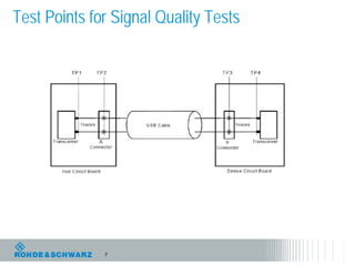
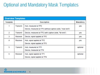
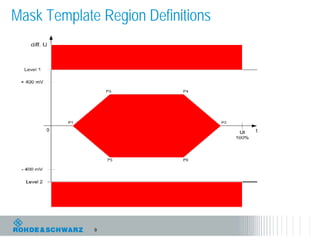
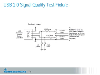


The document outlines the USB 2.0 compliance testing process, focusing on electrical and physical layer tests to ensure reliable communication between USB entities. It details the necessary test points, compliance requirements, and the use of specific tools and fixtures for accurate signal quality measurements. Additionally, it emphasizes the importance of automation in simplifying the testing procedure and reporting results.