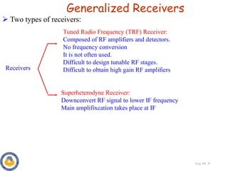
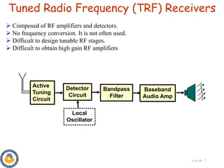
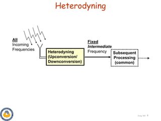
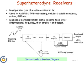
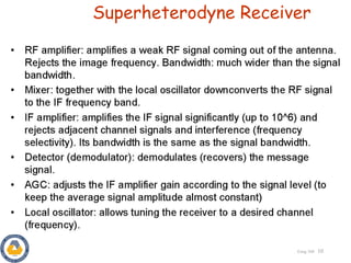
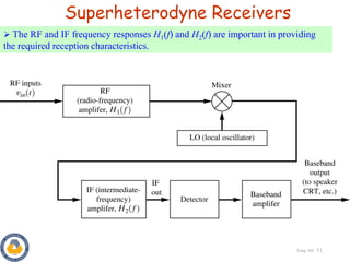
This document discusses superheterodyne receivers and their operation. It describes how a superheterodyne receiver works by downconverting the received radio frequency signal to a lower intermediate frequency using frequency mixing in the receiver mixer with a local oscillator signal. The document outlines the key components of a superheterodyne receiver including the RF amplifier, mixer, local oscillator, intermediate frequency amplifier and detector. It also discusses issues like image frequencies and how they are dealt with in superheterodyne receiver design.

![Eeng 360 2
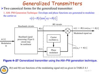
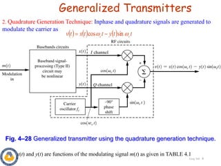
Generalized Transmitters
Re cos
cos sin
Where
c
j t
c
c c
j t
v t g t e R t t t
v t x t t y t t
g t R t e x t jy t
Any type of modulated signal can be represented by
The complex envelope g(t) is a function of the modulating signal m(t)
Transmitter
Modulating
signal
Modulated
signal
Example:
( )
Type of Modulation g(m)
AM : [1 ( )]
PM : p
c
jD m t
c
A m t
A e
](https://image.slidesharecdn.com/lecture5-superheterodynereceivers-230105175853-d0234990/85/Lecture-5-Superheterodyne-Receivers-pdf-2-320.jpg)