Downloaded 300 times


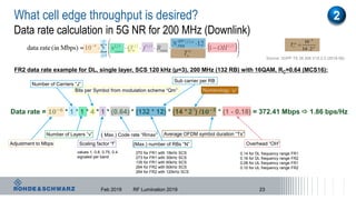
![5G NR bandwidth utilization
17
FR1
SCS
[kHz]
Channel bandwidth [MHz]
5 10 15 20 25 30 40 50 60 70 80 90 100
NRB NRB NRB NRB NRB NRB NRB NRB NRB NRB NRB NRB NRB
15 25 52 79 106 133 160 216 270 n/a n/a n/a n/a n/a
30 11 24 38 51 65 78 106 133 162 189 217 245 273
60 n/a 11 18 24 31 38 51 65 79 93 107 121 135
FR2
SCS
[kHz]
Channel bandwidth [MHz]
50 100 200 400
NRB NRB NRB NRB
60 66 132 264 n/a
120 32 66 132 264
Source: 3GPP TS 38.104 V1.0.0
ı For FR1
Most FDD bands only allow 20 MHz
of bandwidth
100 MHz bandwidth only supported
by TDD bands
19.08MHz
380.16MHz
Dec 2018 5G - A Test&Measurement perspective
COMPANY RESTRICTED](https://image.slidesharecdn.com/5gkeynoterflumination2019-190306161552/85/What-is-5G-17-320.jpg)
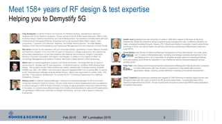
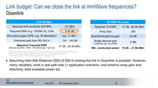
![Link budget: Can we close the link at FR2 frequencies?
ı 5G NR defines for FR2 carrier bandwidths of 50, 100, 200 and 400 MHz
ı What path loss model to use? Just Free Space Path Loss (FSPL)? ABG? 3GPP?
Depends on application scenario: Outdoor? Indoor? Outdoor-to-indoor?
What cell size is required to fulfil business case? 1000m? 500m? 250m?
ı What cell edge performance (e.g. throughput) is expected? 100 Mbps? 200 Mbps?
Feb 2019 RF Lumination 2019
Receiver sensitivity
Bandwidth [MHz] 50 100 200 400
Thermal Noise Level (k*T) -174 dBm/Hz
Bandwidth correction [dB] 77 80 83 86
Typ. UE Noise Figure*) 10 dB
Receiver limit sensitivity [dBm] -97 -94 -91 -88
*) TR38.803 V14.1.0 for co-existence simulations two sets of NF for UE, BS are used: 9 and 11 dB, but as response to ITU WP5D Noise Figure is 10 dB for UE, BS
1
2
19](https://image.slidesharecdn.com/5gkeynoterflumination2019-190306161552/85/What-is-5G-19-320.jpg)
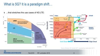
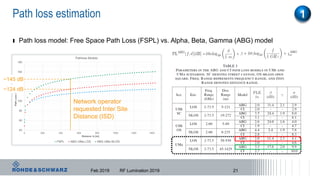
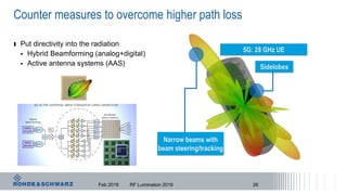
![Free space path loss
Higher frequencies = higher attenuation
Higher frequencies = smaller antennas
𝑃𝑅𝑥
𝑃 𝑇𝑥
= 𝐺 𝑎𝑛𝑡𝑒𝑛𝑛𝑎
𝑐
4𝜋𝒇𝑑
γ
Friis equation
Path Loss 28 GHz
@ d [m]
γ = 2
Free Space
γ = 2.7 to 3.5
Urban Area
1 m - 61,4 dB -92,1 dB (k = 3)
10 m - 81,4 dB -122,1 dB
100 m - 101,4 dB - 151,1 dB
1000 m - 121,4 dB - 181,1 dB
γ = path loss exponent
20Feb 2019 RF Lumination 2019](https://image.slidesharecdn.com/5gkeynoterflumination2019-190306161552/85/What-is-5G-20-320.jpg)
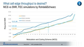
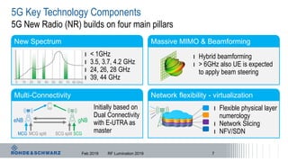
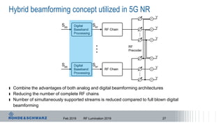
![5G RRH RX
Noise Figure (NF)***) 6 dB
Array Size 256
Beamforming/Array gain 24 dB
Single element gain
(Literature: typ. 5 to 8 dBi)
5 dBi
Let’s check on the uplink…
Feb 2019 RF Lumination 2019
Uplink Link Budget
Device type CPE Smartphone
Total TX EIRP 36 dBm 26 dBm
Path loss 124…145 dB
Bandwidth 200 MHz
Thermal Noise -91 dBm
RX NF 6 dB
Minimum detectable signal -85 dBm
Required SNR (e.g. 16QAM, RC=0.4) 5.22 dB
Total RX beamforming gain 29 dB
RX signal 200 MHz
(Thermal Noise + NF + req.SNR – RX beamforming gain)
-108.78 dBm
Link Margin [dB]
(Total TX EIRP – path loss - RX signal)
-0.22…20.78 -10.22…10.78
UE TX
Device type CPE Smartphone
Conducted power 17 dBm 17 dBm
Array Size (typ.) 32 4
Total Antenna Array gain*) ~19 dBi ~9 dBi
Total TX EIRP for UE**) 36 dBm 26 dBm
ı Closing the uplink link seems problematic for a smartphone, even a CPE
at ISD of 500m; needs a linear, high power amplifier and a high gain
antenna system. Antenna and transmitter characterization is important.
*) Considers antenna feeder losses
**) FCC allows up to +43 dBm for Mobile Stations (FCC Part 30.202)
***) More realistic 5G BTS NF using pre-LNA architecture
25](https://image.slidesharecdn.com/5gkeynoterflumination2019-190306161552/85/What-is-5G-25-320.jpg)
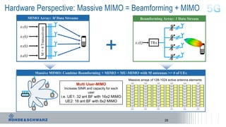
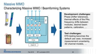
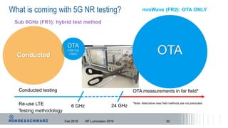


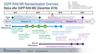


The document outlines key aspects of 5G technology discussed during the RF Lumination 2019 event, focusing on the advancements in radio frequency design and testing. It highlights the components of 5G new radio, including spectrum usage, carrier aggregation, and challenges associated with dual connectivity. The presentation also tackles the testing and measurement perspectives critical for ensuring effective deployment of 5G networks.