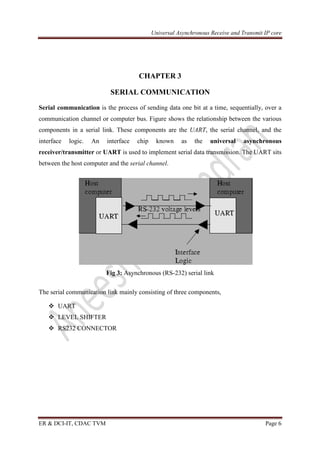
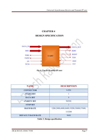
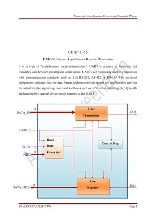
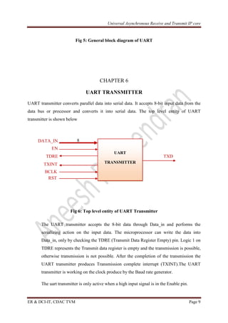
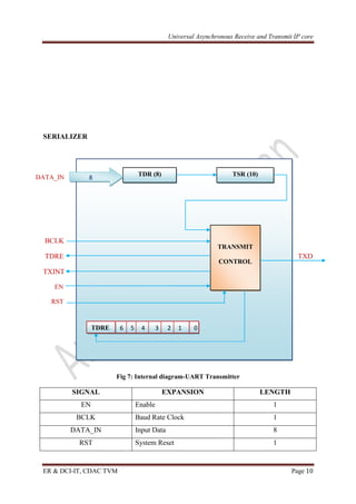
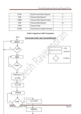
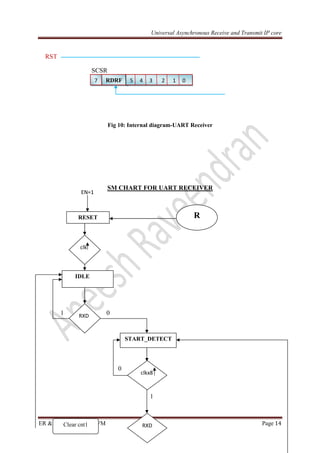
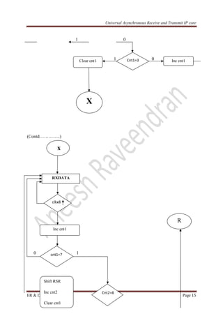
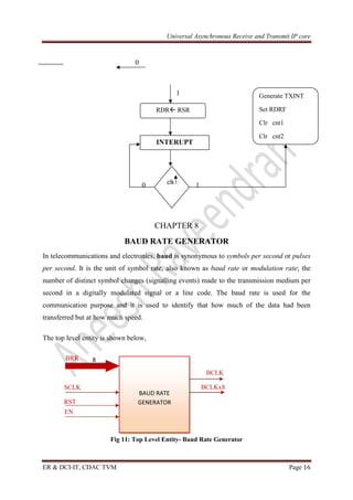
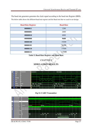
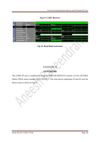
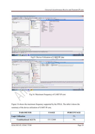
A universal asynchronous receiver-transmitter is a computer hardware device for asynchronous serial communication in which the data format and transmission speeds are configurable.
RS-232 is a popular communications interface for connecting modems and data acquisition devices (i.e. GPS receivers, electronic balances, data loggers, ...) to computers.
In telecommunication and computer science, serial communication is the process of sending data one bit at a time, sequentially, over a communication channel or computer bus. This is in contrast to parallel communication, where several bits are sent as a whole, on a link with several parallel channels.
Serial communication is used for all long-haul communication and most computer networks, where the cost of cable and synchronization difficulties make parallel communication impractical. Serial computer buses are becoming more common even at shorter distances, as improved signal integrity and transmission speeds in newer serial technologies have begun to outweigh the parallel bus's advantage of simplicity (no need for serializer and deserializer, or SerDes) and to outstrip its disadvantages (clock skew, interconnect density). The migration from PCI to PCI Express is an example.
Design and implementation of uart on socIjrdt Journal
Security is primary concern in our day-to-day life. Everyone wants to be as much as secure as possible. The UART (universal asynchronous receiver and transmitter) module provides asynchronous serial communication with external devices such as modems and other computers. The UART can be used to control the process of breaking parallel data from the PC down into serial data that can be transmitted and vice versa for receiving data. The UART allows the devices to communicate without the need to be synchronized. UART is a popular method of serial asynchronous communication. Typically, the UART is connected between a processor and a peripheral. To the processor, the UART appears as an 8-bit read-write parallel port that performs serial-to-parallel conversions for the processor, and vice versa for the peripheral. With the implementation of UART the serial communication is done in high data rate and no interrupts. Baud rate generator provides high data rate and interrupt controller handles all the interrupts. The UART serial communication interface device receives data and converts data from serial to parallel, where as the transmitter performs parallel to serial conversion.
this presentation contains all sort of information regarding USCI(Universal Serial Communication Interface)
UART, SPI, I2C etc.
this will be very helpful to the people those who are planning or starting projects or want to get idea how devices interfaced.
In telecommunications, RS-232 is a standard for serial communication transmission of data. It formally defines the signals connecting between a DTE (data terminal equipment) such as a computer terminal, and a DCE (data circuit-terminating equipment, originally defined as data communication equipment[1]), such as a modem. The RS-232 standard is commonly used in computer serial ports. The standard defines the electrical characteristics and timing of signals, the meaning of signals, and the physical size and pinout of connectors. The current version of the standard is TIA-232-F Interface Between Data Terminal Equipment and Data Circuit-Terminating Equipment Employing Serial Binary Data Interchange, issued in 1997.
IJRET : International Journal of Research in Engineering and Technology is an international peer reviewed, online journal published by eSAT Publishing House for the enhancement of research in various disciplines of Engineering and Technology. The aim and scope of the journal is to provide an academic medium and an important reference for the advancement and dissemination of research results that support high-level learning, teaching and research in the fields of Engineering and Technology. We bring together Scientists, Academician, Field Engineers, Scholars and Students of related fields of Engineering and Technology.
These 25 shareable statistics—about everything from B2B audience engagement and ROI to Facebook and Pinterest—will enhance your content marketing strategy.
Design of FPGA based 8-bit RISC Controller IP core using VHDLAneesh Raveendran
This paper describes the design, development and
implementation of an 8-bit RISC controller IP core. The
controller has been designed using Very high speed integrated circuit Hardware Description Language (VHDL). The design constraints are speed, power and area. This controller is efficient for specific applications and suitable for small applications. This non-pipelined controller has four units: - Fetch, Decode, Execute and a stage control unit. It has an in built program and data memory. Also it has four ports for communicating with other I/O devices. A hierarchical approach has been used so that basic units can be modeled using behavioral programming. The basic
units are combined using structural programming. The design
has been implemented using ALTERA STRATIX II FPGA
UART Serial Communication Module Design and Simulation Based on VHDLIJERA Editor
UART (Universal Asynchronous Receiver Transmitter) is a kind of serial communication protocol; mostly used for short-distance, low speed, low-cost data exchange between computer and peripherals. During the actual industrial production, sometimes we do not need the full functionality of UART, but simply integrate its core part. UART includes three kernel modules which are the baud rate generator, receiver and transmitter. The UART implemented with VHDL language and simulated using XILINX ISE12.1 to achieve compact, stable and reliable data transmission. It’s significant for the design of SOC. The simulation results are completely consistent.
Synthesis & FPGA Implementation of UART IP Soft Coreijsrd.com
this paper presents synthesis and hardware implementation of fully functional Universal Asynchronous Receiver Transmitter Intellectual Property core using XILINX SPARTAN-3 XC3S400 series FPGA. The UART soft core module consists of a transmitter along with baud rate generator and a receiver module with false start bit detection features. This has been implemented using VERILOG hardware description language and synthesized using XILINX ISE development tools. All behavioral simulation of UART module performed using MODELSIM simulator. After successful FPGA implementation transmitter and receiver module was tested by connecting FPGA board with Hyper Terminal software via RS232 interface at a data speed of 9.6 kbps.
Serial Communication Interface with Error Detectioniosrjce
UART is used for serial data communication. UART is a piece of computer hardware that translates
between parallel bits of data and serial bits. UART is usually an integrated circuit used for serial
communications over a computer or peripheral device serial port. Bits have to be moved from one place to
another using wires or some other medium. Over many miles, the expense of the wires becomes large. To reduce
the expense of long communication links carrying several bits in parallel, data bits are sent sequentially. Errors
may occur either internally or externally while we transmit information from source to destination. The errors
generated during the transmission would affect the performance of the overall system. In order to reduce the
errors we should incorporate any error detecting schemes like hamming decoder, check parity systems etc.
Different serial communication devices are available.
"Emblogic.com" is the best education center in India to assist you about serial port device driver and their development as well. To know more about these kind of training program, visit our professional website.
Implementation of Universal Asynchronous Receiver and TransmitterIJERA Editor
Universal Asynchronous Receiver Transmitter (UART) is the serial communication protocol that is used for data exchange between computer & peripherals. UART is a low velocity, short-distance, low-cost protocol. UART includes three modules which are received, the baud rate generator and transmitter. The UART design with Very High Description Language can be integrated into the Field Programmable Gate Array to achieve stable data transmission and to make system reliable and compact. In the result and simulation part, this project will focus on check the receive data with error free & baud rate generation at different frequencies. Before synthesizing of UART a baud rate generator is incorporated into the system. We use the frequency divider which sets itself to required frequency for the functionality at lower frequency. All modules are designed using VERILOG and implemented on Xilinx Suite development board.
Hands On Data Communications, Networking and TCP/IP TroubleshootingLiving Online
More and more people who work in plants need to understand how data from the field is transmitted to the control room and even to Manufacturing Execution Systems located in head offices situated considerable distances from the plant. It is a technological marvel and this manual helps you to understand the flow of information and the various techniques involved in it.
MORE INFORMATION: http://www.idc-online.com/content/hands-data-communications-networking-and-tcpip-troubleshooting-30?id=37
Read/Write control logic:
The Read/Write Control logic interfaces the 8251A with CPU, determines the functions of the 8251A according to the control word written into its control register.
It monitors the data flow.
This section has three registers and they are control register, status register and data buffer.
The active low signals RD, WR, CS and C/D(Low) are used for read/write operations with these three registers.
When C/D(low) is high, the control register is selected for writing control word or reading status word.
Forklift Classes Overview by Intella PartsIntella Parts
Discover the different forklift classes and their specific applications. Learn how to choose the right forklift for your needs to ensure safety, efficiency, and compliance in your operations.
For more technical information, visit our website https://intellaparts.com
Explore the innovative world of trenchless pipe repair with our comprehensive guide, "The Benefits and Techniques of Trenchless Pipe Repair." This document delves into the modern methods of repairing underground pipes without the need for extensive excavation, highlighting the numerous advantages and the latest techniques used in the industry.
Learn about the cost savings, reduced environmental impact, and minimal disruption associated with trenchless technology. Discover detailed explanations of popular techniques such as pipe bursting, cured-in-place pipe (CIPP) lining, and directional drilling. Understand how these methods can be applied to various types of infrastructure, from residential plumbing to large-scale municipal systems.
Ideal for homeowners, contractors, engineers, and anyone interested in modern plumbing solutions, this guide provides valuable insights into why trenchless pipe repair is becoming the preferred choice for pipe rehabilitation. Stay informed about the latest advancements and best practices in the field.
Welcome to WIPAC Monthly the magazine brought to you by the LinkedIn Group Water Industry Process Automation & Control.
In this month's edition, along with this month's industry news to celebrate the 13 years since the group was created we have articles including
A case study of the used of Advanced Process Control at the Wastewater Treatment works at Lleida in Spain
A look back on an article on smart wastewater networks in order to see how the industry has measured up in the interim around the adoption of Digital Transformation in the Water Industry.
Democratizing Fuzzing at Scale by Abhishek Aryaabh.arya
Presented at NUS: Fuzzing and Software Security Summer School 2024
This keynote talks about the democratization of fuzzing at scale, highlighting the collaboration between open source communities, academia, and industry to advance the field of fuzzing. It delves into the history of fuzzing, the development of scalable fuzzing platforms, and the empowerment of community-driven research. The talk will further discuss recent advancements leveraging AI/ML and offer insights into the future evolution of the fuzzing landscape.
Vaccine management system project report documentation..pdfKamal Acharya
The Division of Vaccine and Immunization is facing increasing difficulty monitoring vaccines and other commodities distribution once they have been distributed from the national stores. With the introduction of new vaccines, more challenges have been anticipated with this additions posing serious threat to the already over strained vaccine supply chain system in Kenya.
Immunizing Image Classifiers Against Localized Adversary Attacksgerogepatton
This paper addresses the vulnerability of deep learning models, particularly convolutional neural networks
(CNN)s, to adversarial attacks and presents a proactive training technique designed to counter them. We
introduce a novel volumization algorithm, which transforms 2D images into 3D volumetric representations.
When combined with 3D convolution and deep curriculum learning optimization (CLO), itsignificantly improves
the immunity of models against localized universal attacks by up to 40%. We evaluate our proposed approach
using contemporary CNN architectures and the modified Canadian Institute for Advanced Research (CIFAR-10
and CIFAR-100) and ImageNet Large Scale Visual Recognition Challenge (ILSVRC12) datasets, showcasing
accuracy improvements over previous techniques. The results indicate that the combination of the volumetric
input and curriculum learning holds significant promise for mitigating adversarial attacks without necessitating
adversary training.
Automobile Management System Project Report.pdfKamal Acharya
The proposed project is developed to manage the automobile in the automobile dealer company. The main module in this project is login, automobile management, customer management, sales, complaints and reports. The first module is the login. The automobile showroom owner should login to the project for usage. The username and password are verified and if it is correct, next form opens. If the username and password are not correct, it shows the error message.
When a customer search for a automobile, if the automobile is available, they will be taken to a page that shows the details of the automobile including automobile name, automobile ID, quantity, price etc. “Automobile Management System” is useful for maintaining automobiles, customers effectively and hence helps for establishing good relation between customer and automobile organization. It contains various customized modules for effectively maintaining automobiles and stock information accurately and safely.
When the automobile is sold to the customer, stock will be reduced automatically. When a new purchase is made, stock will be increased automatically. While selecting automobiles for sale, the proposed software will automatically check for total number of available stock of that particular item, if the total stock of that particular item is less than 5, software will notify the user to purchase the particular item.
Also when the user tries to sale items which are not in stock, the system will prompt the user that the stock is not enough. Customers of this system can search for a automobile; can purchase a automobile easily by selecting fast. On the other hand the stock of automobiles can be maintained perfectly by the automobile shop manager overcoming the drawbacks of existing system.
About
Indigenized remote control interface card suitable for MAFI system CCR equipment. Compatible for IDM8000 CCR. Backplane mounted serial and TCP/Ethernet communication module for CCR remote access. IDM 8000 CCR remote control on serial and TCP protocol.
• Remote control: Parallel or serial interface.
• Compatible with MAFI CCR system.
• Compatible with IDM8000 CCR.
• Compatible with Backplane mount serial communication.
• Compatible with commercial and Defence aviation CCR system.
• Remote control system for accessing CCR and allied system over serial or TCP.
• Indigenized local Support/presence in India.
• Easy in configuration using DIP switches.
Technical Specifications
Indigenized remote control interface card suitable for MAFI system CCR equipment. Compatible for IDM8000 CCR. Backplane mounted serial and TCP/Ethernet communication module for CCR remote access. IDM 8000 CCR remote control on serial and TCP protocol.
Key Features
Indigenized remote control interface card suitable for MAFI system CCR equipment. Compatible for IDM8000 CCR. Backplane mounted serial and TCP/Ethernet communication module for CCR remote access. IDM 8000 CCR remote control on serial and TCP protocol.
• Remote control: Parallel or serial interface
• Compatible with MAFI CCR system
• Copatiable with IDM8000 CCR
• Compatible with Backplane mount serial communication.
• Compatible with commercial and Defence aviation CCR system.
• Remote control system for accessing CCR and allied system over serial or TCP.
• Indigenized local Support/presence in India.
Application
• Remote control: Parallel or serial interface.
• Compatible with MAFI CCR system.
• Compatible with IDM8000 CCR.
• Compatible with Backplane mount serial communication.
• Compatible with commercial and Defence aviation CCR system.
• Remote control system for accessing CCR and allied system over serial or TCP.
• Indigenized local Support/presence in India.
• Easy in configuration using DIP switches.
Universal Asynchronous Receive and transmit IP core
1. Universal Asynchronous Receive and Transmit IP core
ER & DCI-IT, CDAC TVM Page 2
Universal Asynchronous Receive and transmit IP core
Aneesh Raveendran
aneeshr2020@gmail.com
ER&DCI Institute of Technology,
Centre for Development of Advanced Computing(C-DAC),
Thiruvananthapuram, Kerala
CHAPTER 2
2. Universal Asynchronous Receive and Transmit IP core
ER & DCI-IT, CDAC TVM Page 3
INTRODUCTION
The RS-232 serial communication protocol is a standard protocol used in asynchronous serial
communication. It is a primary protocol used over modem line. It is used for connecting DTE
(Data Terminal Equipment) and DCE (Data Circuit terminating Equipment).The protocol was
standardised by EIA (Electronic Industry Association). The standard defines the electrical
characteristics, timing of signals, the meaning of signals, the physical size and pin out of
connectors.
RS232 physical properties:
The RS232 standard describes a communication method capable of communicating in
different environments. This has had its impact on the maximum allowable voltages etc. on
the pins. The maximum baud rate defined for example is 20 kbps. With current devices like
the 16550A UART, maximum speeds of 1.5 Mbps are allowed.
Voltages:
The signal level of the RS232 pins can have two states. A high bit, or mark state is identified
by a negative voltage and a low bit or space state uses a positive value. This might be a bit
confusing, because in normal circumstances, high logical values are defined by high voltages
also. The voltage limits are shown below.
Level
Transmitter
capable (V)
Receiver
capable (V)
Space state (0) +5 ... +15 +3 ... +25
Mark state (1) -5 ... -15 -3 ... -25
Undefined - -3 ... +3
Table 1: RS232 voltage values
NOTE:
Despite the high voltages present, it is not possible to destroy the serial port by short circuiting. Only
applying external voltages with high currents may eventually burn out the driver chips. Still then, the
UART won't be damaged in most cases.
Maximum cable length:
3. Universal Asynchronous Receive and Transmit IP core
ER & DCI-IT, CDAC TVM Page 4
The maximum cable length is 50 feet, or the cable length equal to a capacitance of 2500 pF.
This means that using a cable with low capacitance allows you to span longer distances
without going beyond the limitations of the standard. If for example UTP CAT-5 cable is
used with a typical capacitance of 17 pF/ft, the maximum allowed cable length is 147 feet.
The cable length mentioned in the standard allows maximum communication speed to occur.
If speed is reduced by a factor 2 or 4, the maximum length increases dramatically. Texas
Instruments has done some practical experiments years ago at different baud rates to test the
maximum allowed cable lengths. Keep in mind, that the RS232 standard was originally
developed for 20 kbps. By halving the maximum communication speed, the allowed cable
length increases a factor ten.
Baud rate Maximum cable length (ft)
19200 50
9600 500
4800 1000
2400 3000
Table 2: RS232 cable length according to Texas Instruments
4. Universal Asynchronous Receive and Transmit IP core
ER & DCI-IT, CDAC TVM Page 5
FRAME FORMAT
A frame is a complete and non-divisible packet of bits. A frame includes both information
(e.g., data and characters) and overhead (e.g., start bit, error checking and stop bits). In
asynchronous serial protocols such as RS-232, the frame consists of one start bit, seven or
eight data bits, parity bits, and stop bits. A timing diagram for an RS-232 frame consisting of
one start bit, 7 data bits, one parity bits and two stop bits is shown below in figure.
Fig 2 : RS-232 Frame (1 start bit, 7 data bits, 1 parity bits, and 2 stop bits)
The start bit is used to signal the beginning of a frame and the stop bit is used to signal the
end of a frame. Parity is used to detect transmission errors. For even parity checking, the
number of 1's in the data plus the parity bit must equal an even number. For odd parity, this
sum must be an odd number. Parity bits are used to detect errors in transmitted data. Before
sending out a frame, the transmitter sets the parity bit so that the frame has either even or odd
parity. The receiver and transmitter have already agreed upon which type of parity check
(even or odd) is being used. When the frame is received, then the receiver checks the parity
of the received frame. If the parity is wrong, then the receiver knows an error occurred in
transmission and the receiver can request that the transmitter re-send the frame.
5. Universal Asynchronous Receive and Transmit IP core
ER & DCI-IT, CDAC TVM Page 6
CHAPTER 3
SERIAL COMMUNICATION
Serial communication is the process of sending data one bit at a time, sequentially, over a
communication channel or computer bus. Figure shows the relationship between the various
components in a serial link. These components are the UART, the serial channel, and the
interface logic. An interface chip known as the universal asynchronous
receiver/transmitter or UART is used to implement serial data transmission. The UART sits
between the host computer and the serial channel.
Fig 3: Asynchronous (RS-232) serial link
The serial communication link mainly consisting of three components,
UART
LEVEL SHIFTER
RS232 CONNECTOR
6. Universal Asynchronous Receive and Transmit IP core
ER & DCI-IT, CDAC TVM Page 7
CHAPTER 4
DESIGN SPECIFICATION
Fig 4: Top level entity-IP core
NAME DESCRIPTION
CONNECTOR 9-PIN
START BIT 1
DATA BIT 8
PARITY BIT NONE
STOP BIT 1
BAUD RATE 1200,2400,4800,9600,19200,38400,57600,
115200
DEFAULT BAUD RATE 9600
Table 3: Design specification
TXINT
DATA_IN
N
BRR
TDRE
EN
SCLK
UART
RXD
TXD
RXINT
RDRF
DATA_OUT
RST
7. Universal Asynchronous Receive and Transmit IP core
ER & DCI-IT, CDAC TVM Page 8
CHAPTER 5
UART-Universal Asynchronous Receiver/Transmitter
It is a type of "asynchronous receiver/transmitter". UART is a piece of hardware that
translates data between parallel and serial forms. UARTs are commonly used in conjunction
with communication standards such as EIA RS-232, RS-422 or RS-485. The universal
designation indicates that the data format and transmission speeds are configurable and that
the actual electric signalling levels and methods (such as differential signalling etc.) typically
are handled by a special driver circuit external to the UART.
8 1 TXD
ENABLE
SCLK
BRR
DA A 8 1 RXDDATA_OUT
8
8 Uart
Transmitter
Baud
Rate
Generator
Uart
Receiver
Control Reg.
DATA_IN
8
8. Universal Asynchronous Receive and Transmit IP core
ER & DCI-IT, CDAC TVM Page 9
Fig 5: General block diagram of UART
CHAPTER 6
UART TRANSMITTER
UART transmitter converts parallel data into serial data. It accepts 8-bit input data from the
data bus or processor and converts it into serial data. The top level entity of UART
transmitter is shown below
8
EN
TDRE TXD
TXINT
Fig 6: Top level entity of UART Transmitter
The UART transmitter accepts the 8-bit data through Data_in and performs the
serializing action on the input data. The microprocessor can write the data into
Data_in, only by checking the TDRE (Transmit Data Register Empty) pin. Logic 1 on
TDRE represents the Transmit data register is empty and the transmission is possible,
otherwise transmission is not possible. After the completion of the transmission the
UART transmitter produces Transmission complete interrupt (TXINT).The UART
transmitter is working on the clock produce by the Baud rate generator.
The uart transmitter is only active when a high input signal is in the Enable pin.
UART
TRANSMITTER
DATA_IN
BCLK
RST
9. Universal Asynchronous Receive and Transmit IP core
ER & DCI-IT, CDAC TVM Page 10
SERIALIZER
BCLK
TDRE TXD
TXINT
EN
RST
SCSR
SERIALIZER
Fig 7: Internal diagram-UART Transmitter
SIGNAL EXPANSION LENGTH
EN Enable 1
BCLK Baud Rate Clock 1
DATA_IN Input Data 8
RST System Reset 1
TDR (8) TSR (10)
TRANSMIT
CONTROL
6 5 4 3 2 1 0TDRE
DATA_IN 8
10. Universal Asynchronous Receive and Transmit IP core
ER & DCI-IT, CDAC TVM Page 11
SCSR Serial Control Status Register 8
TDR Transmit Data Register 8
TDRE Transmit Data Register Empty 1
TSR Transmit Shift Register 10
TXD Transmit Data 1
TXINT Transmission complete Interrupt 1
Table 4: Signals in UART Transmitter
SM CHART FOR UART TRAMSMITTER
0 -- state
--operation
1
--condition
0
1
0 1
RESET
bclk
IDLE
TDRE
TDR Data_in
set TDRE
form TSR
SYNCH
bclk clear TSR(0)
TXDATA
EN=1
11. Universal Asynchronous Receive and Transmit IP core
ER & DCI-IT, CDAC TVM Page 12
0 1
CHAPTER 7
UART RECEIVER
UART receiver converts serial data into parallel data. It performs the de-serializing action on
the input data. The top level entity of UART receiver is shown below
8
EN
RDRF
RXINT RXD
BCLK
RST
Fig 8: Top level entity-UART Receiver
It accepts set of single bits from the input and converts it into a parallel (8-bit) data. The
received data is given to the processor data bus. The processor can read the data from
Receive Data Register (RDR), only the Receive Data Register is full (RDRF). Once the
bclk
Tcnt=9Set TXINT
Clear Tcnt
Reset TDRE
TXD TSR(Tcnt)
inc Tcnt
UART
RECEIVER
DATA_OUT
BCLKx8
12. Universal Asynchronous Receive and Transmit IP core
ER & DCI-IT, CDAC TVM Page 13
RSR (10)
Receive Data register is full, the UART controller make the pin RDRF (Receive Data
Register Full) high. Once the reception is completed the UART controller generates a
Reception complete interrupt (RXINT).
The bit stream coming from the RXD pin is not synchronized with the clock (bclk). If we
attempt to read the RXD at the rising edge of bclk we would have a problem if RXD changed
near the clock edge. And also we would have a setup and hold time problems. To ensure the
start bit an oversampling procedure is used. The uart receiver is active only when a high input
signal is applied to EN pin.
RXD start bit 1st
data bit 2nd
data bit
* * *
BCLKx8
Fig 9: Oversampling
DE-SERIALIZER
EN
RDRF RXD
RXINT
BCLK
BCLKx8
RECEIVE
CONTROL
BCLK
DATA_OUT 8
RSR (10)RDR (8)
13. Universal Asynchronous Receive and Transmit IP core
ER & DCI-IT, CDAC TVM Page 14
RST
SCSR
Fig 10: Internal diagram-UART Receiver
SM CHART FOR UART RECEIVER
1 0
0
1
RDRF 5 4 3 2 1 07
RESET
clk
IDLE
RXD
START_DETECT
clkx8
RXDClear cnt1
R
EN=1
14. Universal Asynchronous Receive and Transmit IP core
ER & DCI-IT, CDAC TVM Page 15
1 0
1 0
(Contd…………..)
0 1
Cnt1=3 Inc cnt1Clear cnt1
X
x
RXDATA
clkx8
Inc cnt1
cnt1=7
Cnt2=8
Shift RSR
Inc cnt2
Clear cnt1
R
15. Universal Asynchronous Receive and Transmit IP core
ER & DCI-IT, CDAC TVM Page 16
0
1
0 1
CHAPTER 8
BAUD RATE GENERATOR
In telecommunications and electronics, baud is synonymous to symbols per second or pulses
per second. It is the unit of symbol rate, also known as baud rate or modulation rate; the
number of distinct symbol changes (signalling events) made to the transmission medium per
second in a digitally modulated signal or a line code. The baud rate is used for the
communication purpose and it is used to identify that how much of the data had been
transferred but at how much speed.
The top level entity is shown below,
BRR
BCLK
SCLK
RST
Fig 11: Top Level Entity- Baud Rate Generator
8
EN
RDR RSR
Generate TXINT
Set RDRF
Clr cnt1
Clr cnt2
clk
INTERUPT
BAUD RATE
GENERATOR
BCLKx8
16. Universal Asynchronous Receive and Transmit IP core
ER & DCI-IT, CDAC TVM Page 17
The baud rate generator generates the clock signal according to the baud rate Register (BRR).
The below table shows the different baud rate register and the Baud rate that we used in our design.
Baud Rate Register Baud Rate
00000011 1200
00000001 2400
00000010 4800
00000000 9600
00000100 19200
00000101 38400
00000110 57600
00000111 115200
Table 5: Baud Rate Register and Baud Rate
CHAPTER 9
SIMULATION RESULTS
Fig 12: UART Transmitter
17. Universal Asynchronous Receive and Transmit IP core
ER & DCI-IT, CDAC TVM Page 18
Fig 13: UART Receiver
Fig 14: Baud Rate Generator
CHAPTER 10
SYNTHESIS
The UART IP core is synthesized using ALTERA QUARTUS II version 11.0 for ALTERA
Stratix FPGA series number EP2S15F672C3. The total device utilization of uart IP core for
above series is shown in Fig15.
18. Universal Asynchronous Receive and Transmit IP core
ER & DCI-IT, CDAC TVM Page 19
Fig15: Device Utilization of UART IP core
Fig 16: Maximum Frequency of UART IP core
Figure 16 shows the maximum frequency supported by the FPGA. The table 6 shows the
summary of the device utilization of UART IP core.
PARAMETER USAGE PERCENTAGE
Logic Utilization 1%
Combinational ALUTs 151/12480 1%
19. Universal Asynchronous Receive and Transmit IP core
ER & DCI-IT, CDAC TVM Page 20
Dedicated Logic Registers 87/12480 1%
Total Registers 83 0%
Total Pins 33/367 9%
Total PLL and DLL 0 0%
Max. Frequency 396.1MHz
Table 6: Device Utilization -Summary
The figure 17 shows the Register Transfer Level (RTL) view of the UART IP core. It consists
of the RTL view of uart Transmitter, receiver and baud rate generator.
Fig 17: RTL View –Top Level entity
Figure 18 shows the hardware representation of baud rate generator, Fig 19 represents the
hardware representation of uart Receiver, and Fig 20 represents the implementation of state
diagram used for UART Receiver in ALTERA QUARTUS II.
20. Universal Asynchronous Receive and Transmit IP core
ER & DCI-IT, CDAC TVM Page 21
Fig 18: Hadware Representation-Baud Rate Generator
Fig 19: : Hadware Representation-UART Receiver
21. Universal Asynchronous Receive and Transmit IP core
ER & DCI-IT, CDAC TVM Page 22
Fig 20: State Diagram in UART Receiver by ALTERA
22. Universal Asynchronous Receive and Transmit IP core
ER & DCI-IT, CDAC TVM Page 23
Fig 21: Hadware Representation-UART Transmitter
CHAPTER 11
TESTING-UART
The UART IP core is tested using ALTERA STRATIX FPGA series number EP2S15F672C3
and a Personal Computer. The synthesised netlist is downloaded into the FPGA and ready for
testing. The testing structure of the IP core is divided into three phases.
Phase 1: Transmitter testing
The transmitter is tested by placing a random data in DATA_IN pin of the transmitter and a
baud rate generator into the FPGA. After the successful implementation of Transmitter IP
core in the FPGA, then connect the FPGA board into the personal computer. The steps for
transmitter testing are listed below.
1) Place a random data in DATA_IN pin of the UART transmitter.
2) Fix the Baud Rate for transmission
3) Synthesis and download the netlist into the FPGA
4) Connect the FPGA board into the Personal Computer
5) Establish a connection between the FPGA board and Personal Computer using a
Hyper Terminal
6) After the successful connection establishment Press RESET signal in FPGA
7) The stored data is printed in the Hyper Terminal; if this data is matched with stored
data then UART transmitter is working correctly
8) Repeat the above steps for various data and baud rates
Phase 2: Receiver testing
The UART receiver is tested by sending an 8 bit of serial data through RXD pin. The receiver
is tested by downloading uart receiver and a baud rate generator circuit. The steps used are
listed below.
1) Fix the Baud Rate for transmission
2) Synthesis and download the netlist into the FPGA
3) Connect the FPGA board into the Personal Computer
23. Universal Asynchronous Receive and Transmit IP core
ER & DCI-IT, CDAC TVM Page 24
4) Establish a connection between the FPGA board and Personal Computer using a
Hyper Terminal
5) send a character through Hyper Terminal using a key board
6) If the data is received successfully in the FPGA then a LED of FPGA will be glow
7) Repeat the above steps for various data and baud rates
Phase 3: UART IP core testing
The entire UART IP core is tested using a loop back structure. Figure 22 shows the UART
testing structure.
Fig 22: Loop Back Structure
The steps used for UART IP core testing is shown is below.
1) Fix the Baud Rate for transmission
2) Synthesis and download the netlist into the FPGA
3) Connect the FPGA board into the Personal Computer
4) Establish a connection between the FPGA board and Personal Computer using a
Hyper Terminal
5) send a character through Hyper Terminal using a key board
6) Checks the receiver section of the Hyper Terminal, if the received data is matched
with the transmitted data, then the UART IP core is working properly.
7) Repeat the above steps with different baud rates.
Fig 23 shows the test result of UART transmitter with character ‘ A’ at baud rate 115200Hz.
Fig 24 shows the test result of UART transmitter with character ‘ AF’ at baud rate 1200Hz.
Fig 25 shows the test result of entire UART IP core at baud rate 115200Hz.