Downloaded 1,225 times


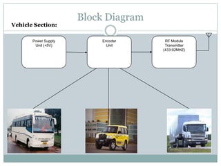
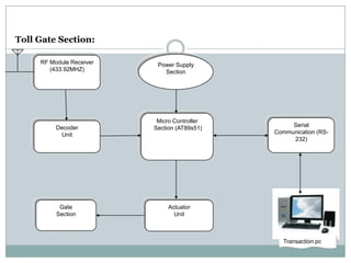
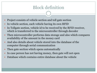

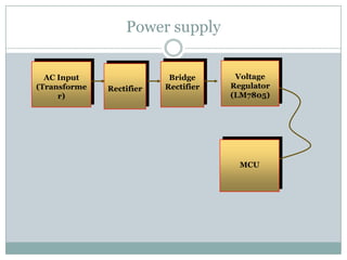


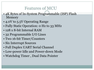


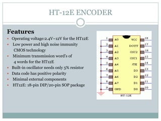


This document describes a proposed optimal integrated operation strategy for a highway toll collection system using wireless technology. The system would use RFID tags in vehicles and RF receivers at toll gates to electronically collect tolls, eliminating delays. It provides block diagrams of the vehicle and toll gate sections, including the main components like RF modules, microcontrollers, encoders/decoders, and power supplies. The document discusses the advantages of this system in reducing time spent at tolls and references sources for further information.


