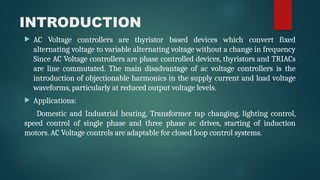
INTRODUCTION
AC Voltagecontrollers are thyristor based devices which convert fixed
alternating voltage to variable alternating voltage without a change in frequency
Since AC Voltage controllers are phase controlled devices, thyristors and TRIACs
are line commutated. The main disadvantage of ac voltage controllers is the
introduction of objectionable harmonics in the supply current and load voltage
waveforms, particularly at reduced output voltage levels.
Applications:
Domestic and Industrial heating, Transformer tap changing, lighting control,
speed control of single phase and three phase ac drives, starting of induction
motors. AC Voltage controls are adaptable for closed loop control systems.
3.
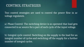
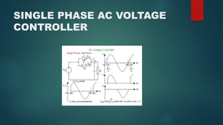
CONTROL STRATEGIES
Two controlstrategies are used to control the power flow in ac
voltage regulators.
a) Phase Control: The switching device is so operated that load gets
connected to ac source for a part of each cycle of the input voltage.
b) Integral cycle control: Switching on the supply to the load for an
integral number of cycles and switching off the supply for a further
number of integral cycles.
5.
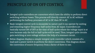
PRINCIPLE OF ONOFF CONTROL
Integral cycle controllers are converters which have the ability to perform direct
switching without losses. This process will directly convert AC to AC without
performing the halfway processes of AC to DC then DC to AC.
Basic integral control cycle is sinusoidal in nature and it can operate by uniting
and removing higher frequency half cycles from AC input. Controllers are
basically turned ON of OFF at the time of half cycles where the voltage input is at
zero because only the full or half cycles will be used. Thus, integral cycle circuits
gain switching at zero voltage without the help of a resonant circuit.
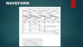
Below diagram displays a simple integral cycle controller which consists of a
load and a power switch to perform the direct conversion. This diagram shows
the conversion of source frequency from a factor of three to one.
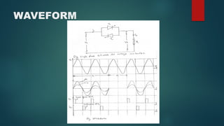
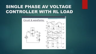
GATE SIGNAL REQUIREMENT
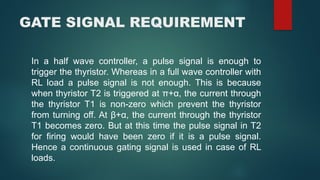
Ina half wave controller, a pulse signal is enough to
trigger the thyristor. Whereas in a full wave controller with
RL load a pulse signal is not enough. This is because
when thyristor T2 is triggered at π+α, the current through
the thyristor T1 is non-zero which prevent the thyristor
from turning off. At β+α, the current through the thyristor
T1 becomes zero. But at this time the pulse signal in T2
for firing would have been zero if it is a pulse signal.
Hence a continuous gating signal is used in case of RL
loads.
11.
PWM CONTROL
PWMAC to AC voltage controllers are widely used in UPS and high power flexible
AC transmission systems. These systems need switching elements which can bear
high voltage. AC/AC line-commutated phase angle control or integral cycle
control with thyristors technology have been widely used; however, this
technique has many drawbacks such as, reduction of power factor at the input
side, plentiful lower order harmonics in supplies, and discontinuity of power flow
to the load sides. The pulse width control using variable DC based method and
the frequency control using carrier frequency based method can theoretically
provide high quality output among all PWM methods with simple design
approach. In PWM control, the converter switches are turned on and off several
times during a half cycle and the output voltage can be controlled by varying
width of pulse.
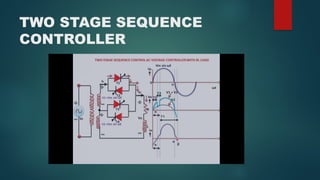
When two ormore sequence control stages are connected, it is possible to have
an improvement in power factor and further reduction in THD (total harmonic
distortion). An n-stage sequence control converter has n windings in the
transformer secondary part with each rated es
/n (the source voltage).
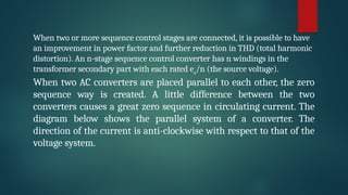
When two AC converters are placed parallel to each other, the zero
sequence way is created. A little difference between the two
converters causes a great zero sequence in circulating current. The
diagram below shows the parallel system of a converter. The
direction of the current is anti-clockwise with respect to that of the
voltage system.
The instantaneouspower flow does not have to equal poweroutput. The difference between the input
and output power must be absorbedor delivered by an energy storage element within the converter.
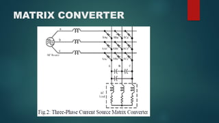
The matrix converter replaces the multiple conversion stages andand uses a matrix of
semiconductor bidirectional switches connecting inputand output terminals. With this general
arrangement of switches, the powerflow through the converter can reverse. Because of the absence of
any energystorage element, the instantaneous power input must be equal to the poweroutput,
assuming idealized zero-loss switches.
However, the reactive power input does not have to equal poweroutput. It can be said again that the
phase angle between the voltages andcurrents at the input can be controlled and does not have to be
the same as atthe output.Three phase matrix converter consists of nine bidirectionalswitches. It has
been arranged into three groups of three switches. Each groupis connected to each phase of the
output. These arrangements of switches canconnect any input phase. In the Figure 2.7 filled circle
shows a closed switch.These 3X3 arrangements can have 512 switching states. Among them only
27switching states are permitted to operate this converter. For safe operation, itshould follow the
given rules.