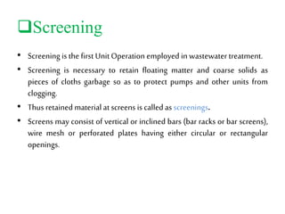
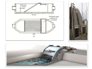
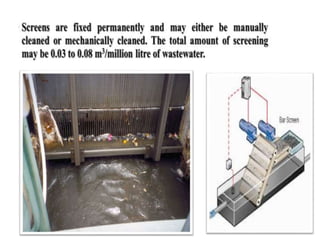
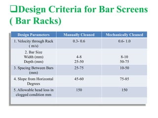
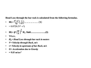
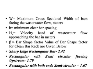
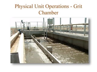
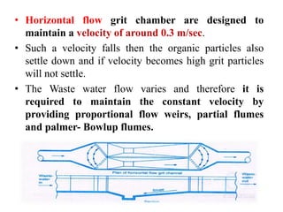
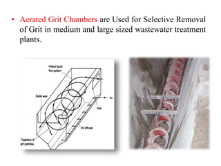
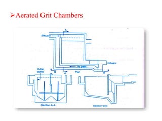
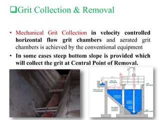
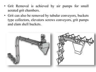
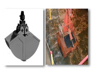
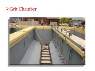
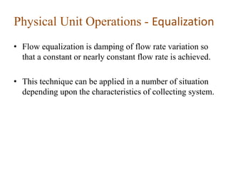
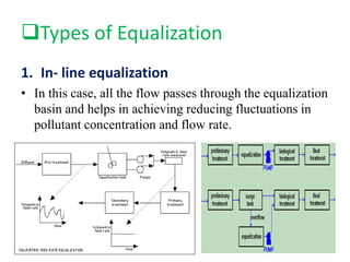
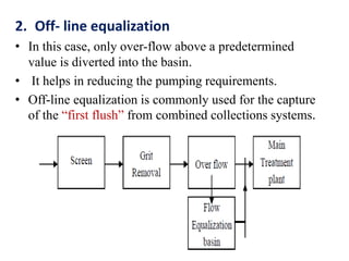
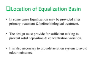
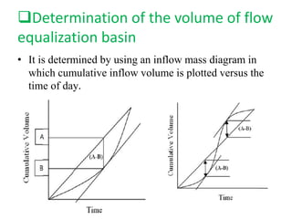
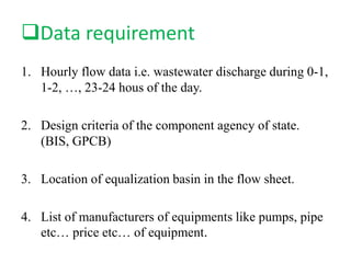
TOPIC- Physical Unit Operation-
Screening, Grit Removal,
Equalization
NAME ENROLL NO.
PATEL JIMI 131100106029
PATEL MILIND 131100106035
PATEL VIRAJ 131100106040
PATEL YASH 131100106042
SHAH ASHIT 131100106051
GUIDED BY: Prof. MANALI SHAH
Prof. UTTEJANA A. CHAUDHARY
Physical Unit Operations -
Screening
Screening
• Screening isthe first Unit Operation employed in wastewater treatment.
• Screening is necessary to retain floating matter and coarse solids as
pieces of cloths garbage so as to protect pumps and other units from
clogging.
• Thus retained material at screens is calledas screenings.
• Screens may consist of vertical or inclined bars (bar racks or bar screens),
wire mesh or perforated plates having either circular or rectangular
openings.
Design Criteria for Bar Screens
( Bar Racks)
Design Parameters Manually Cleaned Mechanically Cleaned
1. Velocity through Rack
( m/s)
0.3- 0.6 0.6- 1.0
2. Bar Size
Width (mm)
Depth (mm)
4-8
25-50
8-10
50-75
3. Spacing Between Bars
(mm)
25-75 10-50
4. Slope from Horizontal
Degrees
45-60 75-85
5. Allowable head loss in
clogged condition mm
150 150
Head Loss through the bar rack is calculated from the following formulae.
• HL=
𝑽 𝟐
−𝒗 𝟐
𝟐𝒈
𝟏
𝟎.𝟕
… … … … … … . . 𝟏
• = 0.0728 (V2- v2)
• HL= 𝜷
𝑾
𝒃
𝟒
𝟑
Hv. Sinθ………………..(2)
• Where,
• HL= Head Loss through bar rack in meters
• V= Velocity through Rack, m/s
• v= Velocity in upstream of bar Rack, m/s
• G= Acceleration due to Gravity
• = 9.81 m/sec2
• W= Maximum Cross Sectional Width of bars
facing the wastewater flow, meters
• b= minimum clear bar spacing
• Hv= Velocity head of wastewater flow
approaching the bar in meters
• β = Bar Shape factor Value of Bar Shape factor
for Clean Bar Rack are Given Below
• Sharp Edge Rectangular Bar- 2.42
• Rectangular with Semi circular faceing
Upstream- 1.79
• Rectangular with both ends Semi-circular – 1.67
Characteristics Quantity &
Composition of Screenings
• Quantity of Screenings depends upon the type of
screen, weather, & Characteristics of wastewater.
• Narrow opening will collect more screenings & hot
weather shall increase the use of water & Wastewater
formation shall be more thereby increasing screenings.
• Quantity of screenings may be 0.03 to 0.08 m3/ ML
with an average of around 0.05 m3/ML
• Screening contain approximately 80 % moisture and
has a normal wt. density of 960 kg/ m3.
• Screening are odorous and attract flies.
Design of BAR Screens
Following Information are Required for design:
• Peak Wet Weather flow.
• Peak Dry Weather flow.
• Hydraulic Design of Influent Conduit.
• Treatment Plant Design Criteria Specified by Bureau of Indian
Standards or other Recognized agency.
• Equipment Manufacturers, their specifications for equipment.
• Velocity through bars
• Information on Existing facility if plant is to be expanded.
• Bar Spacing and head loss constrained through the rack & Through
entire plant.
• Existing Site Plan with Contours.
• Velocities through Screen Chamber.
Design Example
• Design Bar Screen for a Peak flow of 50 MLD.
Assume Other data, Maximum Rate of flow in
m3/Sec
= 50 x 10 6 x 10-3 = 0.5787 m3/sec
24 x 60 x 60
•Let Us Assume the velocity through the screen as
0.8 m/sec
•Net Area of Screen= 0.5787
0.8
= 0.7234 m 2
• Let us use bars of 10 mm x 50 mm with 10 mm dimensions facing the flow, at a
spacing of 40 mm between the bars. So,
• Gross Area = s + t
Net Area s
= Clear Spacing + Bar Thickness
Clear Spacing
Therefore, Gross area in our Case
= Net Area x { Clear Spacing + Bar Thickness }
Clear Spacing
Gross Area = 0.7234 x 40 + 10
40
= 0.9043
Keep Screen at 45 0 Inclination with horizontal then Gross Area required
= 0.9043
Sin 45
= 1.2788 m 2
• Velocity in the approach Channel i.e. Slightly
Upstream of Bar Rack
• = 0.8 x 40
50
= 0.64 m/sec
Thus we have
V= 0.8 m/sec
v= 0.64 m/sec
• Therefore,
• HL=
𝑽𝟐−𝒗𝟐
𝟐𝒈
𝟏
𝟎.𝟕
• = 0.0729 ( V2- v2)
• = 0.0729 ( 0.8 2 – 0.64 2)
• = 0.017 m
• = 1.7 cm
• This will be the head-loss when the screen is
clean
• V= 2 x 0.8
= 1.6 m/sec
&
• HL= 0.0729 ( 1.6 2 – 0.64 2)
= 0.157 m
= 15.7 cm
• So to reduce the head loss frequently cleaning of screen
is required.
Physical Unit Operations - Grit
Chamber
Grit Removal in Grit Chamber
• Sand, ash, Cinder, Bone Chip, egg shells, etc., of size
less than 0.2 mm are included in grit.
• It is therefore possible to remove grit from the waste
water easily by reducing the wastewater velocity in
long channel called as grit channel.
• The velocity is reduced to about 0.3 m/sec.
• The settled grit is washed before its disposal.
• Grit Chamber is provided for the purpose of removal of
silt and sand particles mainly so that the same will not
cause, the wear and tear of vanes of pumps, clogging of
pipes, as well as, valve operation difficult.
• Cementing effects are also prevented in settling tanks
and digester by removal of grit.
• Grit Removal Unit may be a grit Channel, Grit
Chamber or a Grit Basin.
• The Word grit chamber shall be used in subsequent
discussion.
• There are two types of grit chambers
1. Horizontal flow Grit Chambers
2. Aerated Grit Chamber
• Horizontal flow grit chamber are designed to
maintain a velocity of around 0.3 m/sec.
• Such a velocity falls then the organic particles also
settle down and if velocity becomes high grit particles
will not settle.
• The Waste water flow varies and therefore it is
required to maintain the constant velocity by
providing proportional flow weirs, partial flumes
and palmer- Bowlup flumes.
• Aerated Grit Chambers are Used for Selective Removal
of Grit in medium and large sized wastewater treatment
plants.
Aerated Grit Chambers
Grit Collection & Removal
• Mechanical Grit Collection in velocity controlled
horizontal flow grit chambers and aerated grit
chambers is achieved by the conventional equipment
• In some cases steep bottom slope is provided which
will collect the grit at Central Point of Removal.
• Grit Removal is achieved by air pumps for small
aerated grit chambers.
• Grit can also be removed by tubular conveyors, buckets
type collectors, elevators screws conveyors, grit pumps
and clam shell buckets.
Quantity of Grit
• Grit Quantity varies greatly. It depends upon the
following factors:
• Type of Sewerage System i.e. Separate or Combined
Sewerage System
• Climate Condition
• Soil Type
• Sewer Grades
• Type of Industrial Wastewaters
• Relative Use of Garbage and grinders
• The grit quantity may range from 5 to 200 m3/ Million
Cubic Meter of Wastewater. The typical Value can be
Considered as 30 m3/ million Cubic meter of
wastewater.
Grit Disposal
• Various methods are Used for Grit Disposal
1. Sanitary Landfill: In low lying areas or large natural
pits the grit is disposed. Such a method of disposal is
preferred when site of disposal is far away from city
or town.
2. Land Spreading
3. Incineration with Sludge: Incineration is burning at
very high temperature in excess Oxygen. City solid
waste can be incinerated. Sludge and grit can be taken
to the incinerator for burning. Grit can also be buried
when its quantity is small.
Sanitary Landfill
Land Spreading
Incineration with Sludge
Design of Grit Chambers
Following Information should be collected for designing of the
grit chambers
• Wastewater Characteristics and Size of Grit particles to be
removed.
• Design average, peak and lowest flow.
• Information about existing plant if it is to be expanded.
• Type of Grit Chamber to be provided i.e. Horizontal flow, aerated
etc.
• Influent pipe data and static head force main and hydraulic grade
line in case grit removal preceded pumping station.
• Head loss constraints for Grit Removal Efficiency.
• Treatment plant design criteria by Bureau of Indian Standards.
• Detention time = 40 to 60 sec
• Horizontal flow velocity = 15 to 30 cm/sec
approximately
• = 4
• Where g =acceleration due to gravity =9.81
m/sec2
• Ss =Sp Gravity of Grit =2.65
• D=dia of Grit in m
g(Ss -1)d
Design Criteria for Horizontal Flow Grit
Chambers
• Surface Overflow Rate (SOR)
= 500-1500 m3/m2/day
• Length to Breadth Ratio = 6 to 15
• Length to depth Ratio = 10 to 30
• Depth= (1.5 to 2) + free board
• Free Board = 0.75 to 1.0 m
Design Example
• Design a Suitable Grit Chamber to Cater a town
of 2 Lakh population with 150 l/capita/day
Sewage Contribution
• Assume Peak Factor = 1.5
• Maximum Sewage Contribution per day
= Average Contribution x Peak factor
= 150 x 200000 x 1.5 litres
= 150 x 200000 x 1.5 m 3
1000
= 45000 m3
• 45000 m3 sewage produced daily i.e. in
• 24 x 60 x 60= 86400 Seconds
• Therefore Maximum Sewage Discharge
• = 45000 m3/ Sec
86400
= 0.52 m3/Sec
•Assume horizontal velocity 0.3 m/sec and detention time
50 sec
•Therefore Length of the tank Required
= Velocity x Detention Time
= 0.3 x 50
= 15 m
• Now Settling Velocity of Grit Particles are governed by
Hazen’s Modified Equation as Given Below:
• Vs= 60.6 (Ss-1) d (3t + 70)
100
Where, t= temp of Waste water 0 C
d= dia of particle in cm
Vs= Settling Velocity in cm/sec
Ss= Sp Gravity of Grit, 2.65
If Ss= 2.65 above equation becomes
Vs= d (3t + 70)
Taking, t= 27 0C
Vs= 3 m/sec
• We want to remove 0.2 mm particle so Settling
Velocity = 3 cm/sec
• Therefore Depth of Tank= 3.0 cm/sec x 50 sec.3
= 150 cm
= 1.5 m
• Taking Length to Width Ratio as 10 : 1
• Width of the tank = 1.5m
• Now, Check for SOR Surface Overflow Rate
• Width= 1.5 m
• Length=15 m
• Plan Area= 1.5 x 15 = 22.5 m2
• Max Sewage flow = 45000 m3/day
• Max SOR = 45000 m3/day
22.5 m2
= 2000 m3/m2/day
Which is higher than permitted as per Criteria
So, take length: Width ratio as 6:1
Therefore Width= 2.5 m
Therefore Plan Area= 2.5 x 15
= 37.5 m2
Therefore Max SOR= 45000 m3/ day
37.5 m2
= 1200 m3/m2/day
Which is less than 1500 therefore O.K.
Grit Chamber
Physical Unit Operations - Equalization
• Flow equalization is damping of flow rate variation so
that a constant or nearly constant flow rate is achieved.
• This technique can be applied in a number of situation
depending upon the characteristics of collecting system.
Types of Equalization
1. In- line equalization
• In this case, all the flow passes through the equalization
basin and helps in achieving reducing fluctuations in
pollutant concentration and flow rate.
2. Off- line equalization
• In this case, only over-flow above a predetermined
value is diverted into the basin.
• It helps in reducing the pumping requirements.
• Off-line equalization is commonly used for the capture
of the “first flush” from combined collections systems.
Location of Equalization Basin
• In some cases Equalization may be provided after
primary treatment & before biological treatment.
• The design must provide for sufficient mixing to
prevent solid deposition & concentration variation.
• It is also necessary to provide aeration system to avoid
odour nuissance.
Determination of the volume of flow
equalization basin
• It is determined by using an inflow mass diagram in
which cumulative inflow volume is plotted versus the
time of day.
Data requirement
1. Hourly flow data i.e. wastewater discharge during 0-1,
1-2, …, 23-24 hous of the day.
2. Design criteria of the component agency of state.
(BIS, GPCB)
3. Location of equalization basin in the flow sheet.
4. List of manufacturers of equipments like pumps, pipe
etc… price etc… of equipment.
References
• Water & Waste WaterEngineering By
Prof B.R.Shah
Prof A M Malek
• Google Images
Design Criteria for Horizontal Flow Grit
Chambers
• Detention Time = 40 to 60 Sec
• Horizontal flow velocity = 15 to 30 cm/sec
approximately
• = 4 𝑔 𝑆𝑠 − 1 𝑑
• Where g= Acceleration due to Gravity= 9.81
m/sec2
• Ss= Sp Gravity of Grit= 2.65
• D= dia of Grit in m.

Wwwe

  • 1.
    TOPIC- Physical UnitOperation- Screening, Grit Removal, Equalization NAME ENROLL NO. PATEL JIMI 131100106029 PATEL MILIND 131100106035 PATEL VIRAJ 131100106040 PATEL YASH 131100106042 SHAH ASHIT 131100106051 GUIDED BY: Prof. MANALI SHAH Prof. UTTEJANA A. CHAUDHARY
  • 2.
  • 3.
    Screening • Screening isthefirst Unit Operation employed in wastewater treatment. • Screening is necessary to retain floating matter and coarse solids as pieces of cloths garbage so as to protect pumps and other units from clogging. • Thus retained material at screens is calledas screenings. • Screens may consist of vertical or inclined bars (bar racks or bar screens), wire mesh or perforated plates having either circular or rectangular openings.
  • 6.
    Design Criteria forBar Screens ( Bar Racks) Design Parameters Manually Cleaned Mechanically Cleaned 1. Velocity through Rack ( m/s) 0.3- 0.6 0.6- 1.0 2. Bar Size Width (mm) Depth (mm) 4-8 25-50 8-10 50-75 3. Spacing Between Bars (mm) 25-75 10-50 4. Slope from Horizontal Degrees 45-60 75-85 5. Allowable head loss in clogged condition mm 150 150
  • 7.
    Head Loss throughthe bar rack is calculated from the following formulae. • HL= 𝑽 𝟐 −𝒗 𝟐 𝟐𝒈 𝟏 𝟎.𝟕 … … … … … … . . 𝟏 • = 0.0728 (V2- v2) • HL= 𝜷 𝑾 𝒃 𝟒 𝟑 Hv. Sinθ………………..(2) • Where, • HL= Head Loss through bar rack in meters • V= Velocity through Rack, m/s • v= Velocity in upstream of bar Rack, m/s • G= Acceleration due to Gravity • = 9.81 m/sec2
  • 8.
    • W= MaximumCross Sectional Width of bars facing the wastewater flow, meters • b= minimum clear bar spacing • Hv= Velocity head of wastewater flow approaching the bar in meters • β = Bar Shape factor Value of Bar Shape factor for Clean Bar Rack are Given Below • Sharp Edge Rectangular Bar- 2.42 • Rectangular with Semi circular faceing Upstream- 1.79 • Rectangular with both ends Semi-circular – 1.67
  • 9.
    Characteristics Quantity & Compositionof Screenings • Quantity of Screenings depends upon the type of screen, weather, & Characteristics of wastewater. • Narrow opening will collect more screenings & hot weather shall increase the use of water & Wastewater formation shall be more thereby increasing screenings.
  • 10.
    • Quantity ofscreenings may be 0.03 to 0.08 m3/ ML with an average of around 0.05 m3/ML • Screening contain approximately 80 % moisture and has a normal wt. density of 960 kg/ m3. • Screening are odorous and attract flies.
  • 11.
    Design of BARScreens Following Information are Required for design: • Peak Wet Weather flow. • Peak Dry Weather flow. • Hydraulic Design of Influent Conduit. • Treatment Plant Design Criteria Specified by Bureau of Indian Standards or other Recognized agency. • Equipment Manufacturers, their specifications for equipment. • Velocity through bars • Information on Existing facility if plant is to be expanded. • Bar Spacing and head loss constrained through the rack & Through entire plant. • Existing Site Plan with Contours. • Velocities through Screen Chamber.
  • 12.
    Design Example • DesignBar Screen for a Peak flow of 50 MLD. Assume Other data, Maximum Rate of flow in m3/Sec = 50 x 10 6 x 10-3 = 0.5787 m3/sec 24 x 60 x 60 •Let Us Assume the velocity through the screen as 0.8 m/sec •Net Area of Screen= 0.5787 0.8 = 0.7234 m 2
  • 13.
    • Let ususe bars of 10 mm x 50 mm with 10 mm dimensions facing the flow, at a spacing of 40 mm between the bars. So, • Gross Area = s + t Net Area s = Clear Spacing + Bar Thickness Clear Spacing Therefore, Gross area in our Case = Net Area x { Clear Spacing + Bar Thickness } Clear Spacing Gross Area = 0.7234 x 40 + 10 40 = 0.9043 Keep Screen at 45 0 Inclination with horizontal then Gross Area required = 0.9043 Sin 45 = 1.2788 m 2
  • 14.
    • Velocity inthe approach Channel i.e. Slightly Upstream of Bar Rack • = 0.8 x 40 50 = 0.64 m/sec Thus we have V= 0.8 m/sec v= 0.64 m/sec
  • 15.
    • Therefore, • HL= 𝑽𝟐−𝒗𝟐 𝟐𝒈 𝟏 𝟎.𝟕 •= 0.0729 ( V2- v2) • = 0.0729 ( 0.8 2 – 0.64 2) • = 0.017 m • = 1.7 cm • This will be the head-loss when the screen is clean
  • 16.
    • V= 2x 0.8 = 1.6 m/sec & • HL= 0.0729 ( 1.6 2 – 0.64 2) = 0.157 m = 15.7 cm • So to reduce the head loss frequently cleaning of screen is required.
  • 17.
  • 18.
    Grit Removal inGrit Chamber • Sand, ash, Cinder, Bone Chip, egg shells, etc., of size less than 0.2 mm are included in grit. • It is therefore possible to remove grit from the waste water easily by reducing the wastewater velocity in long channel called as grit channel. • The velocity is reduced to about 0.3 m/sec. • The settled grit is washed before its disposal.
  • 19.
    • Grit Chamberis provided for the purpose of removal of silt and sand particles mainly so that the same will not cause, the wear and tear of vanes of pumps, clogging of pipes, as well as, valve operation difficult. • Cementing effects are also prevented in settling tanks and digester by removal of grit.
  • 20.
    • Grit RemovalUnit may be a grit Channel, Grit Chamber or a Grit Basin. • The Word grit chamber shall be used in subsequent discussion. • There are two types of grit chambers 1. Horizontal flow Grit Chambers 2. Aerated Grit Chamber
  • 21.
    • Horizontal flowgrit chamber are designed to maintain a velocity of around 0.3 m/sec. • Such a velocity falls then the organic particles also settle down and if velocity becomes high grit particles will not settle. • The Waste water flow varies and therefore it is required to maintain the constant velocity by providing proportional flow weirs, partial flumes and palmer- Bowlup flumes.
  • 22.
    • Aerated GritChambers are Used for Selective Removal of Grit in medium and large sized wastewater treatment plants.
  • 23.
  • 24.
    Grit Collection &Removal • Mechanical Grit Collection in velocity controlled horizontal flow grit chambers and aerated grit chambers is achieved by the conventional equipment • In some cases steep bottom slope is provided which will collect the grit at Central Point of Removal.
  • 25.
    • Grit Removalis achieved by air pumps for small aerated grit chambers. • Grit can also be removed by tubular conveyors, buckets type collectors, elevators screws conveyors, grit pumps and clam shell buckets.
  • 27.
    Quantity of Grit •Grit Quantity varies greatly. It depends upon the following factors: • Type of Sewerage System i.e. Separate or Combined Sewerage System • Climate Condition • Soil Type • Sewer Grades • Type of Industrial Wastewaters • Relative Use of Garbage and grinders • The grit quantity may range from 5 to 200 m3/ Million Cubic Meter of Wastewater. The typical Value can be Considered as 30 m3/ million Cubic meter of wastewater.
  • 28.
    Grit Disposal • Variousmethods are Used for Grit Disposal 1. Sanitary Landfill: In low lying areas or large natural pits the grit is disposed. Such a method of disposal is preferred when site of disposal is far away from city or town. 2. Land Spreading 3. Incineration with Sludge: Incineration is burning at very high temperature in excess Oxygen. City solid waste can be incinerated. Sludge and grit can be taken to the incinerator for burning. Grit can also be buried when its quantity is small.
  • 29.
  • 30.
  • 31.
  • 32.
    Design of GritChambers Following Information should be collected for designing of the grit chambers • Wastewater Characteristics and Size of Grit particles to be removed. • Design average, peak and lowest flow. • Information about existing plant if it is to be expanded. • Type of Grit Chamber to be provided i.e. Horizontal flow, aerated etc. • Influent pipe data and static head force main and hydraulic grade line in case grit removal preceded pumping station. • Head loss constraints for Grit Removal Efficiency. • Treatment plant design criteria by Bureau of Indian Standards.
  • 33.
    • Detention time= 40 to 60 sec • Horizontal flow velocity = 15 to 30 cm/sec approximately • = 4 • Where g =acceleration due to gravity =9.81 m/sec2 • Ss =Sp Gravity of Grit =2.65 • D=dia of Grit in m g(Ss -1)d Design Criteria for Horizontal Flow Grit Chambers
  • 34.
    • Surface OverflowRate (SOR) = 500-1500 m3/m2/day • Length to Breadth Ratio = 6 to 15 • Length to depth Ratio = 10 to 30 • Depth= (1.5 to 2) + free board • Free Board = 0.75 to 1.0 m
  • 35.
    Design Example • Designa Suitable Grit Chamber to Cater a town of 2 Lakh population with 150 l/capita/day Sewage Contribution • Assume Peak Factor = 1.5 • Maximum Sewage Contribution per day = Average Contribution x Peak factor = 150 x 200000 x 1.5 litres = 150 x 200000 x 1.5 m 3 1000 = 45000 m3
  • 36.
    • 45000 m3sewage produced daily i.e. in • 24 x 60 x 60= 86400 Seconds • Therefore Maximum Sewage Discharge • = 45000 m3/ Sec 86400 = 0.52 m3/Sec •Assume horizontal velocity 0.3 m/sec and detention time 50 sec •Therefore Length of the tank Required = Velocity x Detention Time = 0.3 x 50 = 15 m
  • 37.
    • Now SettlingVelocity of Grit Particles are governed by Hazen’s Modified Equation as Given Below: • Vs= 60.6 (Ss-1) d (3t + 70) 100 Where, t= temp of Waste water 0 C d= dia of particle in cm Vs= Settling Velocity in cm/sec Ss= Sp Gravity of Grit, 2.65 If Ss= 2.65 above equation becomes Vs= d (3t + 70) Taking, t= 27 0C Vs= 3 m/sec
  • 38.
    • We wantto remove 0.2 mm particle so Settling Velocity = 3 cm/sec • Therefore Depth of Tank= 3.0 cm/sec x 50 sec.3 = 150 cm = 1.5 m • Taking Length to Width Ratio as 10 : 1 • Width of the tank = 1.5m
  • 39.
    • Now, Checkfor SOR Surface Overflow Rate • Width= 1.5 m • Length=15 m • Plan Area= 1.5 x 15 = 22.5 m2 • Max Sewage flow = 45000 m3/day • Max SOR = 45000 m3/day 22.5 m2 = 2000 m3/m2/day Which is higher than permitted as per Criteria
  • 40.
    So, take length:Width ratio as 6:1 Therefore Width= 2.5 m Therefore Plan Area= 2.5 x 15 = 37.5 m2 Therefore Max SOR= 45000 m3/ day 37.5 m2 = 1200 m3/m2/day Which is less than 1500 therefore O.K.
  • 41.
  • 42.
    Physical Unit Operations- Equalization • Flow equalization is damping of flow rate variation so that a constant or nearly constant flow rate is achieved. • This technique can be applied in a number of situation depending upon the characteristics of collecting system.
  • 43.
    Types of Equalization 1.In- line equalization • In this case, all the flow passes through the equalization basin and helps in achieving reducing fluctuations in pollutant concentration and flow rate.
  • 44.
    2. Off- lineequalization • In this case, only over-flow above a predetermined value is diverted into the basin. • It helps in reducing the pumping requirements. • Off-line equalization is commonly used for the capture of the “first flush” from combined collections systems.
  • 45.
    Location of EqualizationBasin • In some cases Equalization may be provided after primary treatment & before biological treatment. • The design must provide for sufficient mixing to prevent solid deposition & concentration variation. • It is also necessary to provide aeration system to avoid odour nuissance.
  • 46.
    Determination of thevolume of flow equalization basin • It is determined by using an inflow mass diagram in which cumulative inflow volume is plotted versus the time of day.
  • 47.
    Data requirement 1. Hourlyflow data i.e. wastewater discharge during 0-1, 1-2, …, 23-24 hous of the day. 2. Design criteria of the component agency of state. (BIS, GPCB) 3. Location of equalization basin in the flow sheet. 4. List of manufacturers of equipments like pumps, pipe etc… price etc… of equipment.
  • 48.
    References • Water &Waste WaterEngineering By Prof B.R.Shah Prof A M Malek • Google Images
  • 50.
    Design Criteria forHorizontal Flow Grit Chambers • Detention Time = 40 to 60 Sec • Horizontal flow velocity = 15 to 30 cm/sec approximately • = 4 𝑔 𝑆𝑠 − 1 𝑑 • Where g= Acceleration due to Gravity= 9.81 m/sec2 • Ss= Sp Gravity of Grit= 2.65 • D= dia of Grit in m.