Deals with primary sedimentation tanks for the primary treatment of sewage. settling column test, settling profile graph construction and use of the settling profile graph for the design of primary sedimentation tank. both circular and rectangular settling tanks are described here.
Lecture notes of Environmental Engineering-II as per Solapur university syllabus of TE CIVIL.
Prepared by
Prof S S Jahagirdar,
Associate Professor,
N K Orchid college of Engg and Technology,
Solapur
Lecture notes of Environmental Engineering-II as per Solapur university syllabus of TE CIVIL.
Prepared by
Prof S S Jahagirdar,
Associate Professor,
N K Orchid college of Engg and Technology,
Solapur
L8- Sedimentation aided with coagulation.pptxPRACHI DESSAI
Water treatment is any process that improves the quality of water to make it appropriate for a specific end-use. The end use may be drinking, industrial water supply, irrigation, river flow maintenance, water recreation or many other uses, including being safely returned to the environment. Water treatment removes contaminants and undesirable components, or reduces their concentration so that the water becomes fit for its desired end-use. This treatment is crucial to human health and allows humans to benefit from both drinking and irrigation use.
Sedimentation is an effective techniques involved for treatment of waste water . Various sedimentation techniques are employed world wide for the purpose.
Plain sedimentation is the simplest technique involving quiescent settling or storage of water, such as would take place in a reservoir, lake, or basin, without the aid of chemicals, preferably for a month or longer, particularly if the source water is a sewage-polluted river water.
This presentation covers various plain sedimentation tanks & design considerations of the same .
If you like it ,Please press the thumb up button & donot forget to give your feedback in comments section, it would be extremely valuable . Any query ? Feel free to post in comments section. All the best ! Enjoy !
WATER & WASTE WATER ENGINEERING - water treatment process & unitsEddy Ankit Gangani
This presentation is made with a view to introduce various units & processes carried out in water treatment plant with various trains or say chains of units to meet Indian Standard criteria.
This presentation envisages on theory Of Filtration, Types of Filters, Slow Sand, Rapid Sand and Pressure Filters Including Construction, Operation, Cleaning, Operational Problems In Filters, Design criteria of Slow & Rapid Sand Filter Without Under Drainage System.
Filtration unit in water treatment plantAamir Patni
This document explains deeply about the filtration unit of the water treatment plant. Here we have tried our best to give brief about the types, working, construction and comparison of different filters used in water treatment plant. Hope this will help you.
Deals with the primary treatment of sewage specially for the removal of suspended solids and also for the stabilization of the separated solids. treatment, design and performance details of primary clarifiers, anaerobic ponds, UASB reactors, UASB ponds, and baffled anaerobic reactors are covered in this presentation..
ground water hydrology of Ethiopia.
Hydrology means the science of water. The science deals with occurrence, circulation, and distribution of water of the earth and earth’s atmosphere. Practical applications of hydrology are found in such tasks as the design and operation of hydraulic structures, water supply, wastewater treatment and disposal, irrigation, drainage, hydropower generation, flood control, navigation, erosion and sediment control, salinity control, pollution abatement, recreational use of water, and fish and wildlife protection. Hydrology may be considered to encompass all the hydro-sciences, or defined more strictly as the study of the hydrologic cycle, that is, the endless circulation of water between the earth and its atmosphere. Hydrologic knowledge is applied to the use and control of water resources on the land areas of the earth.
As the branch of science, hydrology is concerned with the water in streams and lakes, rainfall and snowfall, snow and ice on the land and water accruing below the earth’s surface in the pores of the soil & rocks. In general sense, hydrology is very broad subject of on inter-disciplinary nature drawing support from allied sciences, such as meteorology, geology, statistics, chemistry, physics and fluid mechanics hydrology is basically an applied science. It can be used in irrigation, drainage, flood control, water supply, etc. To further emphasize the degree (extent) of applicability, this subject is sometimes classified as: The three important phases of the hydrologic cycle are:
Evaporation and evapotranspiration
Precipitation and
Runoff and
The globe has one-third land and two-thirds Ocean. Evaporation from the surfaces of ponds, lakes, reservoirs, Ocean surfaces, etc. and transpiration from surface vegetation i.e., from plant leaves of cropped land and forests, etc. take place. These vapors rise to the sky, are condensed at higher altitudes by condensation nuclei, and form clouds, resulting in droplet growth. The clouds melt and sometimes burst to result in precipitation of different forms like rain, snow, hail, sleet, mist, dew, and frost. A part of this precipitation flows over the land called runoff and part infilters into the soil, which builds up the groundwater table. The surface runoff joins the streams and the water is stored in reservoirs. A portion of surface runoff and groundwater flow back to the ocean. Again, evaporation starts from the surfaces of lakes, reservoirs, and ocean, and the cycle repeats.
• Of these three phases of the hydrologic cycle, namely, evaporation, precipitation, and runoff, it is the ‘runoff phase’, which is important to a civil engineer since he is concerned with the storage of surface runoff in tanks and reservoirs for the purposes of irrigation, municipal water supply hydroelectric power, etc.
COLLEGE BUS MANAGEMENT SYSTEM PROJECT REPORT.pdfKamal Acharya
The College Bus Management system is completely developed by Visual Basic .NET Version. The application is connect with most secured database language MS SQL Server. The application is develop by using best combination of front-end and back-end languages. The application is totally design like flat user interface. This flat user interface is more attractive user interface in 2017. The application is gives more important to the system functionality. The application is to manage the student’s details, driver’s details, bus details, bus route details, bus fees details and more. The application has only one unit for admin. The admin can manage the entire application. The admin can login into the application by using username and password of the admin. The application is develop for big and small colleges. It is more user friendly for non-computer person. Even they can easily learn how to manage the application within hours. The application is more secure by the admin. The system will give an effective output for the VB.Net and SQL Server given as input to the system. The compiled java program given as input to the system, after scanning the program will generate different reports. The application generates the report for users. The admin can view and download the report of the data. The application deliver the excel format reports. Because, excel formatted reports is very easy to understand the income and expense of the college bus. This application is mainly develop for windows operating system users. In 2017, 73% of people enterprises are using windows operating system. So the application will easily install for all the windows operating system users. The application-developed size is very low. The application consumes very low space in disk. Therefore, the user can allocate very minimum local disk space for this application.
Democratizing Fuzzing at Scale by Abhishek Aryaabh.arya
Presented at NUS: Fuzzing and Software Security Summer School 2024
This keynote talks about the democratization of fuzzing at scale, highlighting the collaboration between open source communities, academia, and industry to advance the field of fuzzing. It delves into the history of fuzzing, the development of scalable fuzzing platforms, and the empowerment of community-driven research. The talk will further discuss recent advancements leveraging AI/ML and offer insights into the future evolution of the fuzzing landscape.
Immunizing Image Classifiers Against Localized Adversary Attacksgerogepatton
This paper addresses the vulnerability of deep learning models, particularly convolutional neural networks
(CNN)s, to adversarial attacks and presents a proactive training technique designed to counter them. We
introduce a novel volumization algorithm, which transforms 2D images into 3D volumetric representations.
When combined with 3D convolution and deep curriculum learning optimization (CLO), itsignificantly improves
the immunity of models against localized universal attacks by up to 40%. We evaluate our proposed approach
using contemporary CNN architectures and the modified Canadian Institute for Advanced Research (CIFAR-10
and CIFAR-100) and ImageNet Large Scale Visual Recognition Challenge (ILSVRC12) datasets, showcasing
accuracy improvements over previous techniques. The results indicate that the combination of the volumetric
input and curriculum learning holds significant promise for mitigating adversarial attacks without necessitating
adversary training.
Industrial Training at Shahjalal Fertilizer Company Limited (SFCL)MdTanvirMahtab2
This presentation is about the working procedure of Shahjalal Fertilizer Company Limited (SFCL). A Govt. owned Company of Bangladesh Chemical Industries Corporation under Ministry of Industries.
Welcome to WIPAC Monthly the magazine brought to you by the LinkedIn Group Water Industry Process Automation & Control.
In this month's edition, along with this month's industry news to celebrate the 13 years since the group was created we have articles including
A case study of the used of Advanced Process Control at the Wastewater Treatment works at Lleida in Spain
A look back on an article on smart wastewater networks in order to see how the industry has measured up in the interim around the adoption of Digital Transformation in the Water Industry.
Hybrid optimization of pumped hydro system and solar- Engr. Abdul-Azeez.pdffxintegritypublishin
Advancements in technology unveil a myriad of electrical and electronic breakthroughs geared towards efficiently harnessing limited resources to meet human energy demands. The optimization of hybrid solar PV panels and pumped hydro energy supply systems plays a pivotal role in utilizing natural resources effectively. This initiative not only benefits humanity but also fosters environmental sustainability. The study investigated the design optimization of these hybrid systems, focusing on understanding solar radiation patterns, identifying geographical influences on solar radiation, formulating a mathematical model for system optimization, and determining the optimal configuration of PV panels and pumped hydro storage. Through a comparative analysis approach and eight weeks of data collection, the study addressed key research questions related to solar radiation patterns and optimal system design. The findings highlighted regions with heightened solar radiation levels, showcasing substantial potential for power generation and emphasizing the system's efficiency. Optimizing system design significantly boosted power generation, promoted renewable energy utilization, and enhanced energy storage capacity. The study underscored the benefits of optimizing hybrid solar PV panels and pumped hydro energy supply systems for sustainable energy usage. Optimizing the design of solar PV panels and pumped hydro energy supply systems as examined across diverse climatic conditions in a developing country, not only enhances power generation but also improves the integration of renewable energy sources and boosts energy storage capacities, particularly beneficial for less economically prosperous regions. Additionally, the study provides valuable insights for advancing energy research in economically viable areas. Recommendations included conducting site-specific assessments, utilizing advanced modeling tools, implementing regular maintenance protocols, and enhancing communication among system components.
Cosmetic shop management system project report.pdfKamal Acharya
Buying new cosmetic products is difficult. It can even be scary for those who have sensitive skin and are prone to skin trouble. The information needed to alleviate this problem is on the back of each product, but it's thought to interpret those ingredient lists unless you have a background in chemistry.
Instead of buying and hoping for the best, we can use data science to help us predict which products may be good fits for us. It includes various function programs to do the above mentioned tasks.
Data file handling has been effectively used in the program.
The automated cosmetic shop management system should deal with the automation of general workflow and administration process of the shop. The main processes of the system focus on customer's request where the system is able to search the most appropriate products and deliver it to the customers. It should help the employees to quickly identify the list of cosmetic product that have reached the minimum quantity and also keep a track of expired date for each cosmetic product. It should help the employees to find the rack number in which the product is placed.It is also Faster and more efficient way.
About
Indigenized remote control interface card suitable for MAFI system CCR equipment. Compatible for IDM8000 CCR. Backplane mounted serial and TCP/Ethernet communication module for CCR remote access. IDM 8000 CCR remote control on serial and TCP protocol.
• Remote control: Parallel or serial interface.
• Compatible with MAFI CCR system.
• Compatible with IDM8000 CCR.
• Compatible with Backplane mount serial communication.
• Compatible with commercial and Defence aviation CCR system.
• Remote control system for accessing CCR and allied system over serial or TCP.
• Indigenized local Support/presence in India.
• Easy in configuration using DIP switches.
Technical Specifications
Indigenized remote control interface card suitable for MAFI system CCR equipment. Compatible for IDM8000 CCR. Backplane mounted serial and TCP/Ethernet communication module for CCR remote access. IDM 8000 CCR remote control on serial and TCP protocol.
Key Features
Indigenized remote control interface card suitable for MAFI system CCR equipment. Compatible for IDM8000 CCR. Backplane mounted serial and TCP/Ethernet communication module for CCR remote access. IDM 8000 CCR remote control on serial and TCP protocol.
• Remote control: Parallel or serial interface
• Compatible with MAFI CCR system
• Copatiable with IDM8000 CCR
• Compatible with Backplane mount serial communication.
• Compatible with commercial and Defence aviation CCR system.
• Remote control system for accessing CCR and allied system over serial or TCP.
• Indigenized local Support/presence in India.
Application
• Remote control: Parallel or serial interface.
• Compatible with MAFI CCR system.
• Compatible with IDM8000 CCR.
• Compatible with Backplane mount serial communication.
• Compatible with commercial and Defence aviation CCR system.
• Remote control system for accessing CCR and allied system over serial or TCP.
• Indigenized local Support/presence in India.
• Easy in configuration using DIP switches.
TECHNICAL TRAINING MANUAL GENERAL FAMILIARIZATION COURSEDuvanRamosGarzon1
AIRCRAFT GENERAL
The Single Aisle is the most advanced family aircraft in service today, with fly-by-wire flight controls.
The A318, A319, A320 and A321 are twin-engine subsonic medium range aircraft.
The family offers a choice of engines
Courier management system project report.pdfKamal Acharya
It is now-a-days very important for the people to send or receive articles like imported furniture, electronic items, gifts, business goods and the like. People depend vastly on different transport systems which mostly use the manual way of receiving and delivering the articles. There is no way to track the articles till they are received and there is no way to let the customer know what happened in transit, once he booked some articles. In such a situation, we need a system which completely computerizes the cargo activities including time to time tracking of the articles sent. This need is fulfilled by Courier Management System software which is online software for the cargo management people that enables them to receive the goods from a source and send them to a required destination and track their status from time to time.
Vaccine management system project report documentation..pdfKamal Acharya
The Division of Vaccine and Immunization is facing increasing difficulty monitoring vaccines and other commodities distribution once they have been distributed from the national stores. With the introduction of new vaccines, more challenges have been anticipated with this additions posing serious threat to the already over strained vaccine supply chain system in Kenya.
2. Introduction
• The extent of treatment required to be given to a
perticular waterdepends upon the characteristics
& quality of the available water & also upon the
quality requirements for intended use.
• In general public water supplies are designed
from the view point of the quality requirements
for drinking water, & simultaneously, they should
be made resonably suitable for industrial
purposes like steam generation, dying, brewing,
etc
• Available water must be made safe, good in
apperance, & attractive to human taste &
tounge.
3. Treatment of Water
• The complete process of removal of
undesirable matter, in order to make the
water acceptable for domestic or Industrial
use, is commonly termed as treatment or
purification of water.
• The object of water treatment is to remove
or reduce these impurities upto acceptable
standards, before water is supplied to the
public.
4. Objectives of Treatment of Water
• To make water odour & taste free
• To make it colourless
• To make the water safe & sparkling for
drinking & domestic purposes
• To remove dissolved gases & turbidity
• To make it free from all objectionable
impurities present in suspension, colloidal
or dissolved form
• to remove harmful bacteria
• To remove hardness
• To make water suitable for a wide variety
of industrial purposes.
5. Various Process & Impurities Removed
Process Impurities Removed
1 Screening Adopted to remove floating matter
2 Aeration
Removes objectionable tastes, odour & dissolved gases
like CO2, H2S. DO is increased. Removes Fe,Mn.
3 Plain Sedimentation
Removes settlebale suspended impurities heavier than
water
4 Sedimentation with Coagulation
Used to cause the sedimentation of colloidal & very fine
suspended particles. some bacteria are also removed
5 Fitration
colloidal & very fine particles escaped from
sendimentation are removed. Micro-organisms are
removed to large extent.
6 Disinfection
All remaining organisms including pathogens are
destroyed
7 Miscellaneous
a) Softening
b) Activated Carbon treatment
a) Hardness is removed
b) Taste & Odour are removed.
6. The purpose of screening process
• Restrict the entry of suspended solids such
as garbage in the water treatment plant.
• Prevent pump, pipe and equipment from
clogging or damage.
• Launched a water course for the next process.
7. Screening
• Screens are generally provided in front of the pumps or
intake works, so as to exclude the large sized particles,
such as debris, animals, trees, branches, bushes, ice,
etc.
• Coarse Screens(trash screens): Are sometimes placed
infront of fine screens. They consist of parallel iron rods
placed vertically or at slight slope, at about 2.5 to 5 cm
apart. The course screens are also now normally kept
inclined at about 450
-600
to the horizontal, so as to
increase the opening area to reduce the flow velocity, &
thus, making screens more effective. While designing
screens, clear opening should have sufficient total area,
so that velocity through them is not more than 0.8 to
1 m/s. The material collected on upstream side is
removed either mannually or mechanically.
14. Screens
• Fine screens: They are usually made of woven
wire mesh with opening not more than 6 mm
square. Fine screens normally get clogged, and
are to be cleaned frequently, hence avoded
these days.
• Movable bar type or Travelling bar screens:
1) Stationary Fine screen- Cleaned by raising it
out of water, & washing off the collected
material. 2) Movable fine screen- they are
endless belts of fine screening or series of
panels of fine wire meshmounted on a chain.
The debris collected on it are discharged into a
trough, usually with the aid of water spray or a
jet.
15.
16. Plain Sedimentation
1. Most of suspended impurities present in water do have
specific gravity greater than that of water.
2. In still water, these impurities will tend to settle down
under gravity, although in normal raw supplies, they
remain in suspension, because of terbulence in water.
• Hence as soon as terbulence is retarded by
offering storage to the water, these impurities tend
to settle down at the bottom of the tank, offering
such storage. This is the principle behind
sedimentation.
• The basin in which the flow of the water is retarded is
called the settling tank or sedimentation tank or
sedimentation basin or clarifier & theoretical average
time for which the water is detained in the tank is
called the detention time.
17. Types of Sedimentation Tank
Sedimentation Tank
Horizontal Flow Tank Vertical/Up flow tank
Cirular/ square/
rectangular in plan
Rectangular Circular
Continuous
flow
type
Intermittant type
(Fill & draw type/Batch-process
Radial Flow with
Central feed
Periferal Feed
31. Design Concepts in Plain Sedimentation
Tank
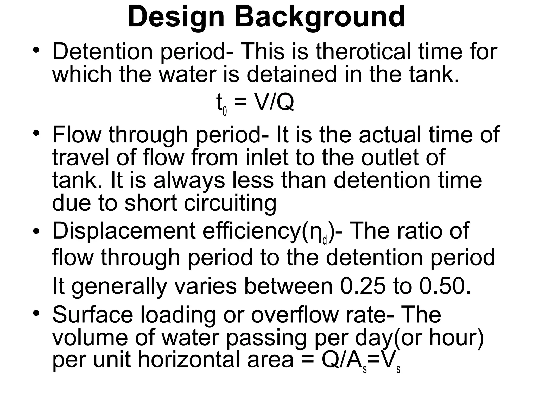
• overflow velocity/overflow rate/surface
overflow rate(SOR)/surface loading
rate(v0) - It is that flow velocity at which
tank is designed to operate.
• vo = Q/As = (volume/time)/ As
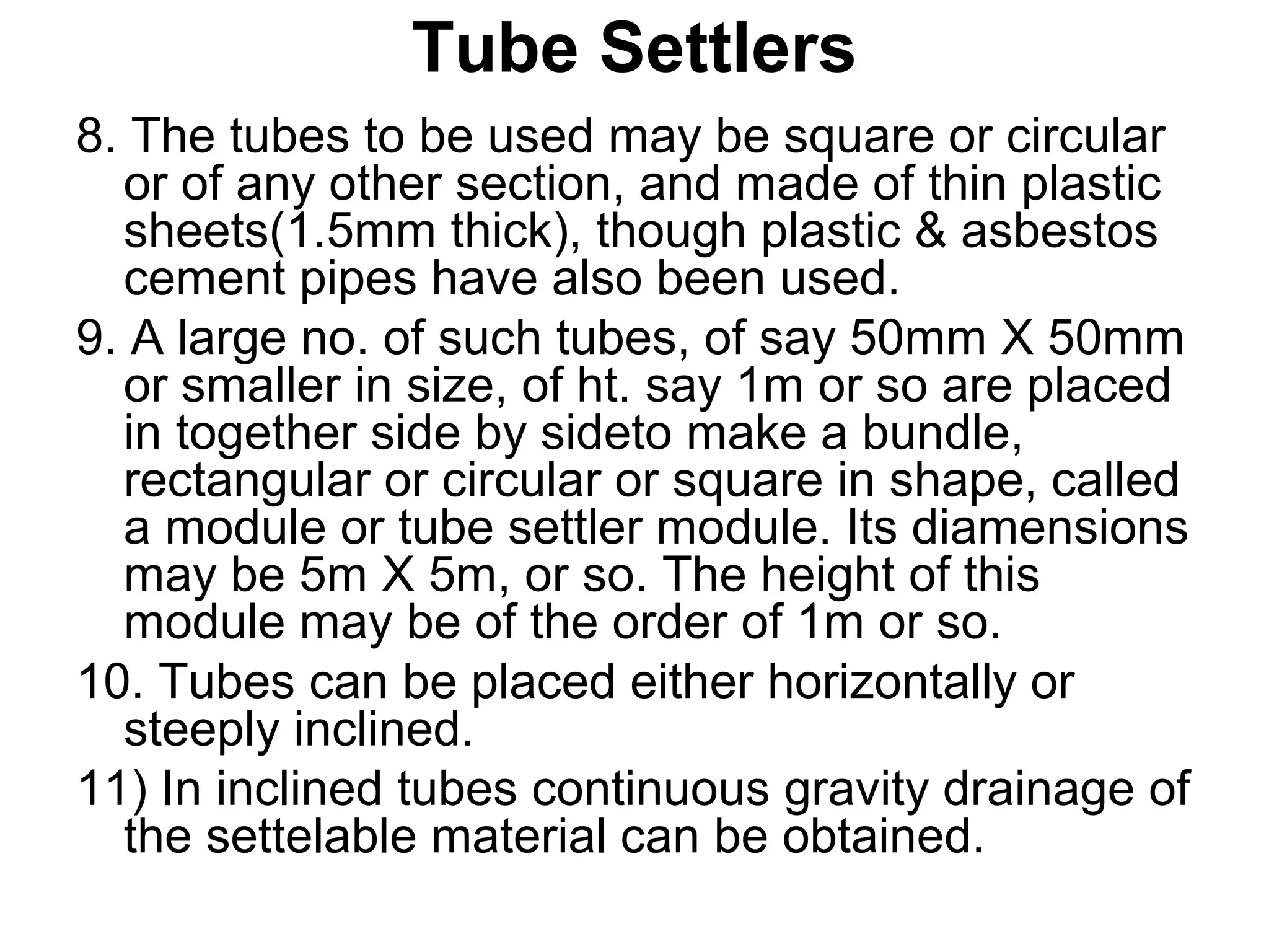
= [(As X Depth)/time]/As = Depth/Time
= Liquid velocity
( The particle removal is independent of
depth of sedimentation tank.)
32. Design Concepts in Plain Sedimentation Tank
• Horizontal sedimentation tank is designed
based on following three assumptions.
1Particles & their velocity vectors are evenly
distributed across the tank cross-section.
2The liquid moves as ideal slug, down the
length of tanlk.
3Any particle hitting the bottom of the tank is
removed.
33. Design Background
• Detention period- This is therotical time for
which the water is detained in the tank.
t0 = V/Q
• Flow through period- It is the actual time of
travel of flow from inlet to the outlet of
tank. It is always less than detention time
due to short circuiting
• Displacement efficiency(ƞd)- The ratio of
flow through period to the detention period
It generally varies between 0.25 to 0.50.
• Surface loading or overflow rate- The
volume of water passing per day(or hour)
per unit horizontal area = Q/As=Vs
34. Design Background
• Weir Loading- Clear water is withdrawn at
the other end through some outlet
arrangement. If it is in the form of weir,
water falling over the weir is called as weir
loading. It is expressed as Kl/day/m
35.
36.
37.
38.
39. Design Criterian for sedimentation tank
• Overflow rates- 12-18 m3
/day/m2
- Type I
24-30 m3
/day/m2
- Type II
• Usual values of depth- 3.0 to 4.5m, with
1.8m as minimum & 6m as maximum.
• Detention period-
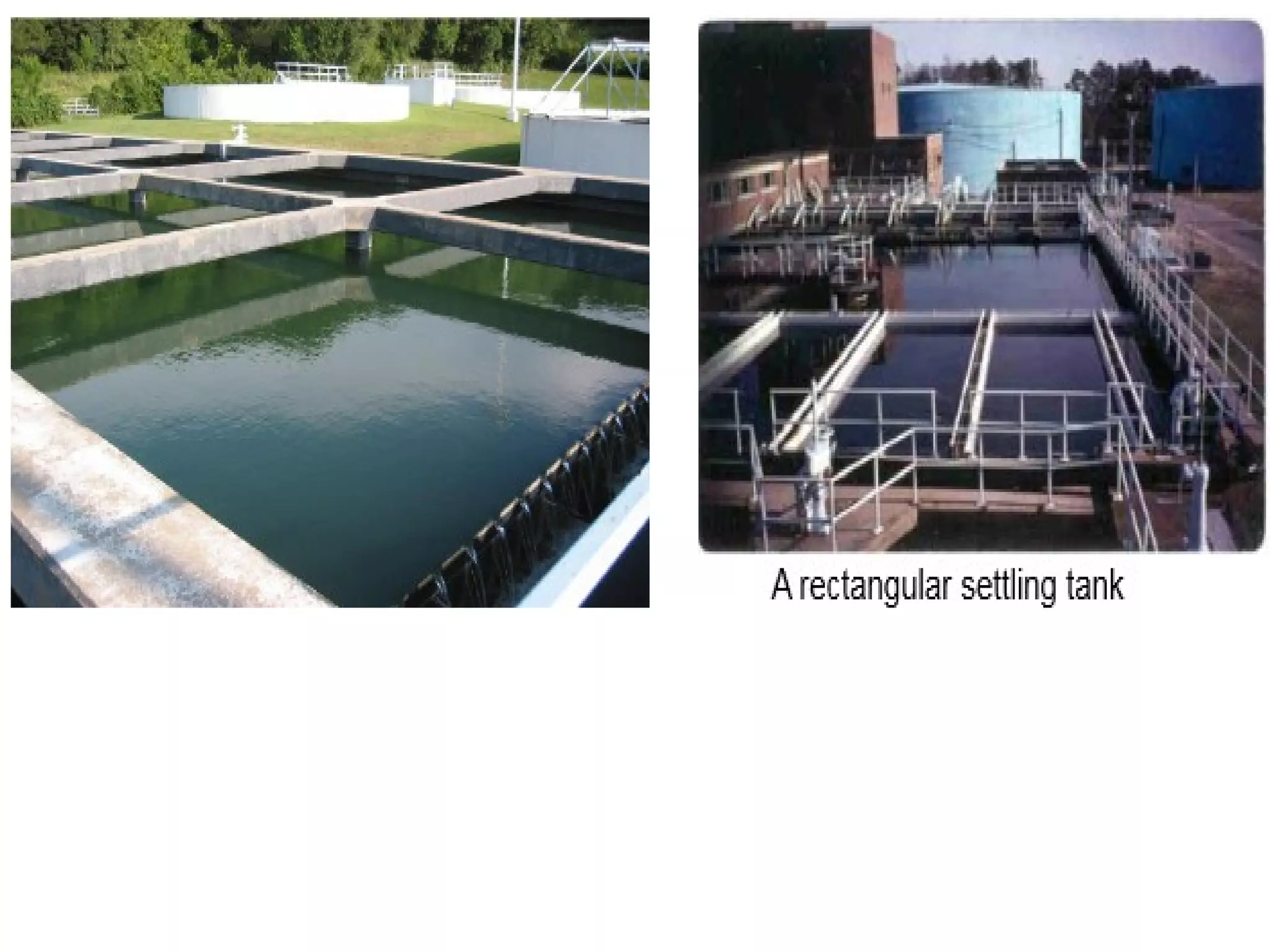
Rectangular Tank= BLH/Q
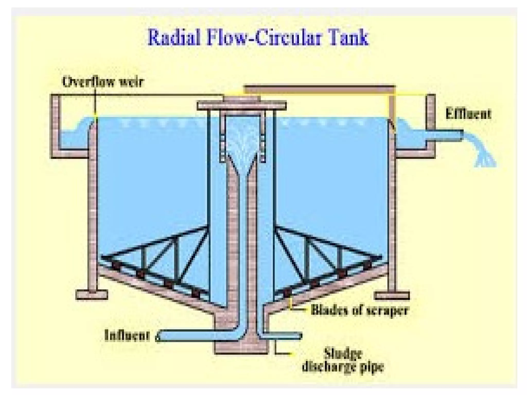
Circular tank= [d2
(0.011d + 0.785H)]/Q
Detension time ranges bet- 4-8hrs - TypeI
2-4hrs - TypeII
Horizontal flow velocity- 0.15 to 0.9 m/min
normally kept as 0.3m/min
L= 1 to 6 times width, usually not allowed to
exceed four time width.
40.
41.
42. Tube Settlers
1.Settling efficiency is primarily dependent
on surface area of tank & is independent
of its depth.
2.Hence sedimentation basin should be
made as shallow as possible.
3.Due to land constrictions, the surface area
has to be limited, & the tank volume is
made up by providing sufficient water
depth in the tank (3 to 5 meters).
4.To reduce depth & to provide multiple
surface areas, horozontal trays are to be
placed in tank, which will divide tank
height into compartments.
43. Tube Settlers
5. Such arrangement increases surface area,
thereby reducing the SOR(v0), hence causing
more particle settlement.
6. Placement of such wide shallow trays,not been
very sucessfull, as they developed problems,
like clogging & odour due to biological growth,
build up of oil & greases.
7. However, very small diameter tubes having high
wetted perimeter relative to wetted area,
providing laminar flow conditins & low surface
loadind rate , have shown good promise. Such
settling devices, called tube settlers, provide
excellent clarification with detention time equal
to or less than 10 minutes.
44. Tube Settlers
8. The tubes to be used may be square or circular
or of any other section, and made of thin plastic
sheets(1.5mm thick), though plastic & asbestos
cement pipes have also been used.
9. A large no. of such tubes, of say 50mm X 50mm
or smaller in size, of ht. say 1m or so are placed
in together side by sideto make a bundle,
rectangular or circular or square in shape, called
a module or tube settler module. Its diamensions
may be 5m X 5m, or so. The height of this
module may be of the order of 1m or so.
10. Tubes can be placed either horizontally or
steeply inclined.
11) In inclined tubes continuous gravity drainage of
the settelable material can be obtained.
45. Tube Settlers
12. In horizontal tubes( Inclined at 50
) auxillary
scouring of settled solids is necessary.
13. The advantage achieved decreases with
increase in angle of inclination(θ) of tubes with
horizontal. Efficiency decreases rapiddly at
angles greater than 400
, but sludge will not slide
automatically with angles less than 600
.
14. Hence 600
inclined tube settlers are prefferd.
15. If one-fifth of outlet end of the basin is coverd
with tube settlers, the effective surface loading of
the basin is halved, or flow through the tank can
be doubled without impairing the effluent quality.
16
50. Assignment No.4
1. What do you mean by treatment of water? State the
objectives of treatment of water.
2. Write short notes on: I) Bar screen II) Tube settlers ( MU-
DEC.-2011, MAY-2010,12)
3. Draw a layout plan for a typical water treatment plant.(MU-
Dec-13)
4. Prove by deriving suitable expression that in an ideal
sedimentation tank the efficiency of removal of discrete
suspended particles is solely dependent on the surface
area.(MU-May-2011,dec 11, may12)
5. Explain the theory of sedimentation.( MU-Dec13)
6. Explain with sketches any two types of sedimentation tank.
7. Solve any three Problems on design of sedimentation tank.
51.
52. Sedimentation Aided With Coagulation
The primary purpose of the
coagulation/flocculation
process is the removal
of turbidity from the
water.
• Turbidity is a cloudy
appearance of water
caused by small
particles suspended
therein.
• Water with little or no
turbidity will be clear.
• Water with a high turbidity
can be very difficult to
properly disinfect.
54. Coagulant aided sedimentation required
to remove following impurities
1. Miscellaneous fragments of animal and
vegetable matter
2. plankton mainly phytoplankton (microscopic
plants).
3. Finely divided colloidal matter and clay.
4. Organic colouring matter partly in solution
and partly in colloidal form.
5. Bacteria and viruses in small extent
6. Complex mixture of organic compounds
55. Coagulation-Flocculation
• In conventional coagulation-flocculation-
sedimentation, a coagulant is added to the
source water to create a attraction among
the suspended particles.
• The mixture is slowly stirred to induce
particles to clump together into “flocs.”
• The water is then moved into a quiet
sedimentation basin to settle out the
solids.
56. Coagulation & Flocculation
• Coagulation is a chemical technique which
is directed towards the destabilisation of
charged colloidal particles.
• Flocculation is the slow mixing technique
which promotes the agglomeration of the
destabilised particles.
57. Coagulation Is
• The addition and rapid mixing of coagulants
• The destabilization of colloidal and fine particles
• The initial aggregation of destabilized particles
Flocculation Is
• The gentle agitation to aggregate destabilized
particles to form rapid-settling floc
58.
59.
60.
61.
62. Theory of Coagulation
Destabilization of colloidal particles
takes place by following ways
Coagulation and flocculation can be
caused by any of the following:
1.Double layer compression
2.Charge neutralization
3.Bridging
4.Colloid entrapment
64. An Electric Double Layer consists
of three parts:
• Surface charge - charged ions (commonly
negative) adsorbed on the particle surface.
• Stern layer - counter ions (charged opposite to the
surface charge) attracted to the particle surface and
closely attached to it by the electrostatic force.
• Diffuse layer - a film of the dispersion medium
(solvent) adjacent to the particle. Diffuse layer
contains free ions with a higher concentration of the
counter ions. The ions of the diffuse layer are
affected by the electrostatic force of the charged
particle.
65. •The amount of coagulant which should
be added to the water will depend on the
zeta potential, a measurement of the
magnitude of electrical charge
surrounding the colloidal particles.
•The zeta potential as the amount of
repulsive force which keeps the particles
in the suspension.
•If the zeta potential is large, then more
coagulants will be needed.
66. •When coagulants(Electrolytes) are
added into the water it changes ionic
concentration.
•Which compresses double layer and
weakens repulsive forces.
•The basic goal of coagulation is to
reduce the net repulsive force.
71. •Bridging occurs when a coagulant
forms threads or fibers which attach
to several colloids, capturing and
binding them together.
•Inorganic primary coagulants and
organic polyelectrolytes both have
then capability of bridging.
•Higher molecular weights mean
longer molecules and more
effective bridging.
74. 1. Aluminum Sulfate or Alum
•To produce the hydroxide floc, enough alkalinity should
present in the water
If alkalinity is not enough, then it should be added. Usually
hydrated lime is used for that purpose (optimum pH is 6.5 –
8.5)
75.
76. Under normal circumstances Dose of Alum varies from 10
to 30 mg/lit of water.
Advantages
1.Alum reduces taste and odour
2.Cheap
3.Easily available
4.Soluble in water
Disadvantages
1. Difficult to dewater the sludge
77. 2. Ferrous Sulfate (Chlorinated Copperas)
•The optimum pH range is 3.5 to 6.5
•At higher pH i.e. 9.5 it removes manganese
•More expensive than alum
•Effective in colour removal.
•Low solubility in water
78.
79. 3. Ferrous Sulfate and lime
•Ferrous sulphate can react with natural calcium
bicarbonate alkalinity in water, but its slow process.
•Hence Lime is added in water.
•Ferric hydroxide is gelatinous floc, which is heavier than
floc formed by alum.
•Optimum pH range is below 7
80.
81. 4. Magnesium carbonate and lime
Byproducts of above reaction forms soluble sludge, so not
commonly used
83. Comparison of Alum and Iron salt
1. Iron salts forms heavy floc as compared to alum, hence
more Solids are removed
2. time of reaction and floc formation is less for iron salts,
hence ‘t’ reduces.
3. Iron salts can work efficiently over wider pH range
4. Iron salts can remove taste and odour.
5. Less mud ball formation as compared to alum
84. 6. Under some cases iron salts are more economical.
7. Iron salts cause staining and promotes growth of iron
bacteria.
8. Iron salts make water more corrosive as compared to alum
9. Handling of iron salts requires skill.
10. More CO2 is formed so water becomes corrosive.
11. Alum Coagulation may not be proper if K or Na are present
in water
88. Mixing devices: Hydraulic mixing in
water flow
a. Channel with baffles
b. Overflow weir
c. Hydraulic jump mixing
89.
90.
91.
92. Mixing devices : Hydraulic mixing in
flocculation tank
A. Vertical flow
B. Horizontal
flow
93.
94. • Horizontally baffled tank
•The water flows horizontally.
•The baffle walls help to create turbulence and thus
facilitate mixing
• Vertically baffled tank
•The water flows vertically. The baffle walls help to create
turbulence and thus facilitate mixing
104. Paddle blade flocculator
•The Main design parameters of flocculator units are:
• mixing time, t
• volume of flocculator V,
• velocity gradient, G
105. Coagulant Aids
•Are used to produce quick-forming, dense and rapid-
settling flocs
•Polyelectrolytes
•pH adjustment
•Alkalinity addition
•Turbidity addition
106. Polyelectrolytes
•Anionic (-vely charged)
•Cationic (+vely charged)
•Polyampholites (both +vely and –vely charged
groups)
•Natural such as starch
•Synthetic (more common in coagulation)
•They aid in coagulation by:
•Chemical bridging
•Interaction between reactive groups on the
polyelectrolyte and the floc
107.
108. pH Adjustment
•Is used if pH of water to be treated is not within the
optimum pH of the coagulant
•pH is increased using lime
•pH is reduced using sulfuric acid
109. Alkalinity Addition
•Is used when natural alkalinity is not enough to produce
good floc
•Hydrated or slaked lime is used
•Soda ash (Na2CO3) is also used (expensive)
110. Turbidity Addition
•Is used to provide sufficient particulate concentration
to achieve rapid coagulation through sufficient inter-
particle collision
•Is done by recycling chemically precipitated sludge
•Bentonite Clays are also used for that purpose
111.
112.
113. Aeration
• Aeration is an operation in which principal of gas
transfer is used.
• Henry's Law states that the amount of a
gas that dissolves in liquid is directly
proportional to the partial pressure of that
gas.
• The process of exposing large surface
of water to the atmosphere & thus
bringing water in intimate contact with
air so as to absorb oxygen is called as
aeration.
114. Objectives of Aeration
• To increase the Oxygen content in water
for imparting freshness.
• To remove CO2 from water.
• To remove volatile substances & gases
like H2S causing bad taste & odour.
• To oxidise iron & manganese so that
these can be precipitated & removed.
• Aeration helps to destroy bacteria.
115. Methods of Aeration
1) Using Fountains,Spray Nozzles: In this
method water is srinkled in air or
atmosphere through special nozzles which
breaks the water into droplets, thus
permitting the escape of dissolved gases
• CO2 is considerably removed ( upto 90%)
• Considerable head of water of the order of
10 to 14m is required.
• Spray nozzles may be either fixed or
movable type
116.
117.
118.
119.
120. Methods of Aeration
2) Gravity or Free fall Aerators
i) Cascade Aerator: In its simplest form it
consists of a series of 3 or 4 steps, either
circular or straight.
Water is allowed to fall through a height of 1
to 3 meters with a fall of about 0.15 to
0.3meters in each step.
This is widely used.
Efficient in raising dissolved O2, but not for
CO2 removal. ( removes 60 to 70% CO2)
Weirs & waterfalls of any kind are cascade
aerators.
126. Aeration by Air Diffusion
• In this method compressed air is bubbled
through the water, so as to throughly
mixed with water.
• Perforated pipes are installed at the
bottom of tank & compressed air is blown
through them.
• The air bubbles travel upward through
water, causes terbulence bring about
aeration.
• Tank has detention period of 15 min. &
depth of 3 to 5m & is continuous flow type.
127. Aeration by Air Diffusion
• Limitations: 1)Inefficient to remove or reduce
tastes & odours caused by I) Non-volatile
substances like oils & algae. II) Chemical
discharge in Industrial waste.
2) Water become corrosive due to over
oxygenation & de-aeration is may be required.
3) It is economical in warmer climate months.
4) Possibility of air-borne contamination
5) Fe & Mn can be precipitated only when organic
matter is absent.
132. Aeration by Trickling Beds or Multiple Trays
• In this method water is allowed to tricke
down the beds of coke supported over
perforated bottom trays & arranged
vertically in series.
• Generally three beds are used, the depth
of each being about 0.6m with a clear
distance of about 0.45m. in between . The
water is applied from top through
perforated disturibution pipes & allowed to
trickle down upto bottom bed.
137. Filteration
• It is a process of removing fine suspended
particles & bacterial impurities from water
by passing it through a porous medium.
Objects:
• To remove suspended, colloidal & other
impurities untrapped by previous process.
• To reduce bacterial load by about 90%
• To produce sparkling & aesthetically
attractive water
• To reduce colour & odour
• To alter the chemical characteristics of
water.
139. Filters
Based on
rate of
Filtration
Based on
material of
filter media
Based on
depth of
filter media
1 Gravity filters
a) Slow sand
filters
b) Rapid sand
Filter
2) Pressure filters
a) Sand filters
b) Anthracite filters
c) Metal fabric filters
d) Diatomaceous earth
filters
a) Deep granular
filters
( dual media &
multimedia granular
filters)
b) Precoat filters
140. Theory of Filteration
• Filteration basically involves
a) Transport Mechanism: Brings small
particles from the solution to the surface of
media. Actions like diffusion, interception,
gravitational settling & hydrodynamic
actions takes place.
b) Attach Mechanism: It assumes the
adhering or retaining of particles over the
grains of filter media. It is occuring due to
electrostatic interactions & specific
adsorption or chemical bridging.
141. Theory of Filteration
• Filters in fact purify the water in
four different process as follows:
1) Mechanical Straining
2) Flocculation & sedimentation
3) Biological metabolism
4) Eletrolytic changes
142. Filter Materials
Sand either fine or course is generally
used as filter media
Sand: Obtained from rocks like
quartzite.
1) It should be free from dirt & other
impurities
2) It should be uniform in nature & size
3) It should be hard & resistant
4) It should not loose more than 5% of
its weight after being placed in HCl for
24 hrs.
143. Filter Materials
Gravel: Gravel used below the sand should be
hard, durable, free from impurities, properly
rounded & have a density of 1600kg/m3
Gravels of different sizes are usually placed in 3-4
layers each of 15-20 cm Depth, with the corsest
size (20 to 60 mm) placed in the bottom-most
layer, & finest size (3-6mm) in the top most
layer.
Effective Size: Is the sieve size in mm through
which 10% of sand by weight passes. It is called
effective diameter D10.(0.2 to 0.4 0.35 to 0.55mm)
Unoformity Coefficient(D60/D10): This is the ratio of
sieve size through which 60% of the sand
passes to the effective size of sand.(1.8-12.5 &
1.3-1.7)
148. Slow Sand Filter
• The various parts of filter are
1) Enclosure tank
2) Filter media
3) Base Material
4) Under-drainage system
5) Inlet & outlet arrangement
6) other appurtenances
149. Slow Sand Filter
Enclosure tank
• Open water-tight rectangular tank, made
of masonry or concrete.
• Bed slope 1 in 100 towards central drain
• Depth- 2.5 to 3.5m
• Plan area 100 to 2000sq. m.
150. Slow Sand Filter
Filter Media:
• sand layers of 90 to 110 cm in depth over
gravel
• D10- 0.2 to 0.4 & D10/D60- 1.8 to 2.5 or3.
• Top 15 cm layer is finer sand.
Base material:
• Consists of 30 to 75 cm thick gravels of
different sizes placed in layers
• Generally 3 to 4 layers each of 15-20 cm
depth are used. Bottom layer- 40-65mm,
intermediate layer- 20 to 40mm & 6 to 20mm,
Top layer 3 to 6mm.
151. Slow Sand Filter
Under-drainage system:
The gravel support is laid on the top of under-drainage
system.
• Under-drainage system consists of central drain &
lateral drains.
• Laterals are open jointed pipe drains or some other
kind of porous drains placed 3 to 5m apart on the
bottom floor & sloping towards main covered drain.
• Laterals collect the filtered water & discharge it into
main drain, which leads the water to filtered water
well.
• Sometimes main drain is placed along one side of
tank, & laterals slope towads it.
155. Rapid Sand Filter
Various parts of this filter are
• Enclosure tank
• Filter media
• Base material
• Under-drainage system
• Other appertenances
156. 1)Enclosure tank
• Open water-tight rectangular tank, made
of masonry or concrete.
• Depth- 2.5 to 3.5m
• In order to achieve uniform distribution of
water, area of filter unit is not kept larger &
is limited to about 10 to 80m2
for each unit.
• N= 1.22 Q N= no. of filter units
Q= Plant capacity in MLD.
157. 2)Filter Media
• Depth of sand layers- 60 to 90cm
• D10- 0.35 to 0.55
• D60/D10- 1.3 to 1.7
3)Base Material
• Base material in addition to supporting
the sand, it distributes the wash water.
• Gravel layers( five to six)- 60 to 90cm
each layer 10 to 15 cm in depth.
• Size of gravel in bottom most layer-20 to
40mm; in intermediate layersbetween 12
to 20 mm, 6 to 12mm & in top most
layerbetween 3 to 6mm.
158. • Careful grading & careful placing of the
material is important as distribution of
wash water is critical function of the gravel
layers.
4) Under-drainage system
• Under-drainage system serves two
purposes
i) to receive & collect the filtered water
ii) to allow the back washing for cleaning
• It should be capable of passing wash
water upward at sufficiently high velocity.
159. • Back washing consists of passing filtered
water upward through the bed at such a
velocity that it causes sand bed to expand
until its thickness is 25 to 40% greater.
• Wash water moves at ahigh rate of 300-
900 lit/min/m2
of filter area.
• various forms of under-drainage systems
are
1)Manifold & lateral system a) perforated
pipe b) pipe & strainer type system
2) Wheeler bottom
3) Porous plate bottom
160. • Other Appurtenances
Wash water troughs
Air compressor
Rate controller
Miscellaneous accessories.
Operational troubles in RSF
Formation of mud balls
Cracking of Filters.