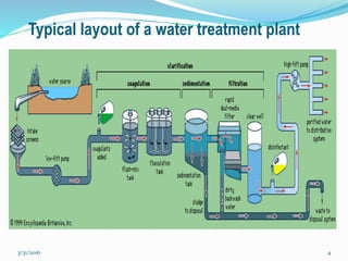
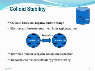
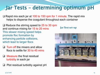
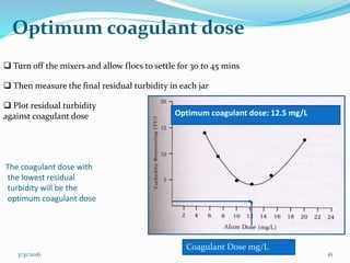
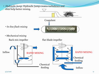
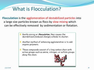
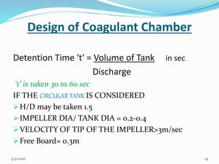
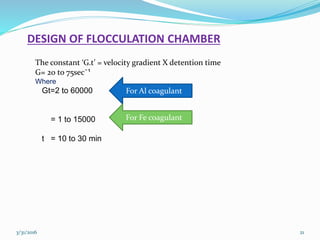
Coagulation and Flocculation
LOKESH SAINI
M.Tech-I´st Semester
Student ID 2015PCE5271
3/31/2016 1
3/31/2016 2
Why coagulation and flocculation?
Various sizes of particles in raw water
Particle diameter (mm) Type Settling velocity
10 Pebble 0.73 m/s
1 Course sand 0.23 m/s
0.1 Fine sand 0.6 m/min
0.01 Silt 8.6 m/d
0.0001 (10 micron) Large colloids 0.3 m/y
0.000001 (1 nano) Small colloids 3 m/million y
Colloids – so small: gravity settling not possible
GravItysettlIng
COAGULATION AND FLOCCULATION
3/31/2016 3
2TYPE SETTLING
3/31/2016 4
Typical layout of a water treatment plant
3/31/2016 5
What is Coagulation?
 Coagulation is the destabilization of colloids by addition of
chemicals that neutralize the negative charges by rapid
mixing.
 The chemicals are known as coagulants, usually higher valence
cationic salts (Al3+, Fe3+ etc.)
 Coagulation is essentially a chemical process
--
-
-
--- --
-
----
--
-
---- --
-
----
The net resultant force is a result of:
1. attractive potential energy (mostly vander Waals forces), Va.
These forces are very strong at short separation distances
2. repulsion potential energy (electrostatic forces), VR.
(by Coulomb’s law).
a 6
1V
r

R 2
1V
r

3/31/2016 8
Colloid Stability
------ ------
Repulsion
Colloid - A Colloid - B
 Colloids have a net negative surface charge
 Electrostatic force prevents them from agglomeration
 Brownian motion keeps the colloids in suspension
H2O
Colloid
 Impossible to remove colloids by gravity settling
Colloidal interaction
3/31/2016 9
Charge reduction
3/31/2016 10
3/31/2016 11
 Typical coagulants
Aluminum sulfate: Al2(SO4)3.14 H2O
Iron salt- Ferric sulfate: Fe2(SO4)3
Iron salt- Ferric chloride: Fe2Cl3
Poly aluminum chloride (PAC): Al2(OH)3Cl3
3/31/2016 12
Jar Tests
Determination of optimum pH
 The jar test – a laboratory procedure to determine the optimum pH
and the optimum coagulant dose
 A jar test simulates the coagulation and flocculation processes
 Fill the jars with raw water sample
(500 or 1000 mL) – usually 6 jars
 Adjust pH of the jars while mixing
using H2SO4 or NaOH/lime
(pH: 5.0; 5.5; 6.0; 6.5; 7.0; 7.5)
 Add same dose of the selected
coagulant (alum or iron) to each jar
(Coagulant dose: 5 or 10 mg/L)
Jar Test
3/31/2016 13
Jar Test set-up
 Rapid mix each jar at 100 to 150 rpm for 1 minute. The rapid mix
helps to disperse the coagulant throughout each container
 Reduce the stirring speed to 25 to 30 rpm
and continue mixing for 15 to 20 mins
This slower mixing speed helps
promote floc formation by
enhancing particle collisions,
which lead to larger flocs
 Turn off the mixers and allow
flocs to settle for 30 to 45 mins
 Measure the final residual
turbidity in each jar
 Plot residual turbidity against pH
Jar Tests – determining optimum pH
3/31/2016 water treatment 14
Optimum pH: 6.3
Jar Tests – optimum pH
3/31/2016 15
Optimum coagulant dose
 Repeat all the previous steps
 This time adjust pH of all jars at
optimum (6.3 found from first test)
while mixing using H2SO4 or
NaOH/lime
 Add different doses of the selected
coagulant (alum or iron) to each jar
(Coagulant dose: 5; 7; 10; 12; 15; 20 mg/L)
 Rapid mix each jar at 100 to 150 rpm for 1 minute. The rapid
mix helps to disperse the coagulant throughout each container
 Reduce the stirring speed to 25 to 30 rpm for 15 to 20 mins
3/31/2016 16
 Turn off the mixers and allow flocs to settle for 30 to 45 mins
 Then measure the final residual turbidity in each jar
 Plot residual turbidity
against coagulant dose
Coagulant Dose mg/L
Optimum coagulant dose: 12.5 mg/L
The coagulant dose with
the lowest residual
turbidity will be the
optimum coagulant dose
Optimum coagulant dose
3/31/2016 17
• Hydraulic Jump: Hydraulic Jump creates turbulence and
thus help better mixing.
• Mechanical mixing
• In-line flash mixing
Inflow
Chemical
feeding
Chemical
feeding
Inflow
Back mix impeller flat-blade impeller
Coagulant
RAPID MIXING RAPID MIXING
3/31/2016 18
What is Flocculation?
Flocculation is the agglomeration of destabilized particles into
a large size particles known as flocs by slow mixing which
can be effectively removed by sedimentation or flotation.
Design of Coagulant Chamber
Detention Time 't' = Volume of Tank in sec
Discharge
‘t’ is taken 30 to 60 sec
IF THE CIRCULAR TANK IS CONSIDERED
H/D may be taken 1.5
IMPELLER DIA/ TANK DIA = 0.2-0.4
VELOCITY OF TIP OF THE IMPELLER>3m/sec
Free Board= 0.3m
3/31/2016 19
3/31/2016 20
3/31/2016 21
DESIGN OF FLOCCULATION CHAMBER
The constant ‘G.t’ = velocity gradient X detention time
G= 20 to 75sec¯¹
Where
Gt=2 to 60000
= 1 to 15000
t = 10 to 30 min
For Al coagulant
For Fe coagulant
3/31/2016 22
MECHANICAL FLOCCULATOR DESIGN
Inlet pipe & Tank Sizing
Depth of the tank = 3 to 4.5m
Detention time ‘t” = 20 to 40 min
Total area of paddles = 10 to 25% of the cross sectional area of the tank
Velocity of flow = 0.2-0.6m/s
Peripheral velocity of blades = 0.2 to 0.6m/s
Outlet velocity = 0.15 to 0.25m/s
Water loss in de sledging = 2%
Velocity in inlet pipe = 1m/s
Free board= 0.5m
Paddle Sizing
Power input ‘P’=G².μ X vol. of tank= ½.Cd.ρ.Ap.(V-v)³
Where,
Cd= Drag coefficient, 1.8
ρ = Density of water at 25̊ c, 997Kg/m³
V = Velocity at the tip blades= 0.4m/s
v = Velocity of the water at tip of blades is 25% of V
V=2π.r.n/60 where r is the paddle length
3/31/2016 23
Clarifier sizing
SoR= 40m³/m²/day
π/4{(Dia of clf)² - (Dia of flocculator)²}= Design flow/SoR
Length of Weir= π.Dia of clf< 300 m³/day
3/31/2016 24
Hydraulic flocculators: simple
technology
3/31/2016 25
Hydraulic Flocculation: Pipe
3/31/2016 26
Hydraulic Flocculation: Pipe
3/31/2016 27
Mechanical
flocculators
3/31/2016 28
Mechanical
flocculators
3/31/2016 29
Mechanical
flocculators
3/31/2016 30
3/31/2016 31
References
1. Manual on water supply and treatment, CPHEEO, Ministry of MOUD, New
Delhi, 1999;201-232:621-625
2. Peavy S. Howard, Rowe, Tchobanoglous, Environmental Engineering, 2014;
120-150
3. Weikipedia on coagulation and flocculation
4. Water treatment: Principlea and design, MWH(2005), (ISBN 04710110183)
5. Unit process in drinking water treatment W. Masschelein(1992), (ISBN
082478678 5)(635 pgs)
6. IS 3025
3/31/2016 32
THANKS

Ppt coagulation and flocculation

  • 1.
    Coagulation and Flocculation LOKESHSAINI M.Tech-I´st Semester Student ID 2015PCE5271 3/31/2016 1
  • 2.
    3/31/2016 2 Why coagulationand flocculation? Various sizes of particles in raw water Particle diameter (mm) Type Settling velocity 10 Pebble 0.73 m/s 1 Course sand 0.23 m/s 0.1 Fine sand 0.6 m/min 0.01 Silt 8.6 m/d 0.0001 (10 micron) Large colloids 0.3 m/y 0.000001 (1 nano) Small colloids 3 m/million y Colloids – so small: gravity settling not possible GravItysettlIng
  • 3.
  • 4.
    3/31/2016 4 Typical layoutof a water treatment plant
  • 5.
    3/31/2016 5 What isCoagulation?  Coagulation is the destabilization of colloids by addition of chemicals that neutralize the negative charges by rapid mixing.  The chemicals are known as coagulants, usually higher valence cationic salts (Al3+, Fe3+ etc.)  Coagulation is essentially a chemical process -- - - --- -- - ---- -- - ---- -- - ----
  • 6.
    The net resultantforce is a result of: 1. attractive potential energy (mostly vander Waals forces), Va. These forces are very strong at short separation distances 2. repulsion potential energy (electrostatic forces), VR. (by Coulomb’s law). a 6 1V r  R 2 1V r 
  • 8.
    3/31/2016 8 Colloid Stability ------------ Repulsion Colloid - A Colloid - B  Colloids have a net negative surface charge  Electrostatic force prevents them from agglomeration  Brownian motion keeps the colloids in suspension H2O Colloid  Impossible to remove colloids by gravity settling
  • 9.
  • 10.
  • 11.
    3/31/2016 11  Typicalcoagulants Aluminum sulfate: Al2(SO4)3.14 H2O Iron salt- Ferric sulfate: Fe2(SO4)3 Iron salt- Ferric chloride: Fe2Cl3 Poly aluminum chloride (PAC): Al2(OH)3Cl3
  • 12.
    3/31/2016 12 Jar Tests Determinationof optimum pH  The jar test – a laboratory procedure to determine the optimum pH and the optimum coagulant dose  A jar test simulates the coagulation and flocculation processes  Fill the jars with raw water sample (500 or 1000 mL) – usually 6 jars  Adjust pH of the jars while mixing using H2SO4 or NaOH/lime (pH: 5.0; 5.5; 6.0; 6.5; 7.0; 7.5)  Add same dose of the selected coagulant (alum or iron) to each jar (Coagulant dose: 5 or 10 mg/L) Jar Test
  • 13.
    3/31/2016 13 Jar Testset-up  Rapid mix each jar at 100 to 150 rpm for 1 minute. The rapid mix helps to disperse the coagulant throughout each container  Reduce the stirring speed to 25 to 30 rpm and continue mixing for 15 to 20 mins This slower mixing speed helps promote floc formation by enhancing particle collisions, which lead to larger flocs  Turn off the mixers and allow flocs to settle for 30 to 45 mins  Measure the final residual turbidity in each jar  Plot residual turbidity against pH Jar Tests – determining optimum pH
  • 14.
    3/31/2016 water treatment14 Optimum pH: 6.3 Jar Tests – optimum pH
  • 15.
    3/31/2016 15 Optimum coagulantdose  Repeat all the previous steps  This time adjust pH of all jars at optimum (6.3 found from first test) while mixing using H2SO4 or NaOH/lime  Add different doses of the selected coagulant (alum or iron) to each jar (Coagulant dose: 5; 7; 10; 12; 15; 20 mg/L)  Rapid mix each jar at 100 to 150 rpm for 1 minute. The rapid mix helps to disperse the coagulant throughout each container  Reduce the stirring speed to 25 to 30 rpm for 15 to 20 mins
  • 16.
    3/31/2016 16  Turnoff the mixers and allow flocs to settle for 30 to 45 mins  Then measure the final residual turbidity in each jar  Plot residual turbidity against coagulant dose Coagulant Dose mg/L Optimum coagulant dose: 12.5 mg/L The coagulant dose with the lowest residual turbidity will be the optimum coagulant dose Optimum coagulant dose
  • 17.
    3/31/2016 17 • HydraulicJump: Hydraulic Jump creates turbulence and thus help better mixing. • Mechanical mixing • In-line flash mixing Inflow Chemical feeding Chemical feeding Inflow Back mix impeller flat-blade impeller Coagulant RAPID MIXING RAPID MIXING
  • 18.
    3/31/2016 18 What isFlocculation? Flocculation is the agglomeration of destabilized particles into a large size particles known as flocs by slow mixing which can be effectively removed by sedimentation or flotation.
  • 19.
    Design of CoagulantChamber Detention Time 't' = Volume of Tank in sec Discharge ‘t’ is taken 30 to 60 sec IF THE CIRCULAR TANK IS CONSIDERED H/D may be taken 1.5 IMPELLER DIA/ TANK DIA = 0.2-0.4 VELOCITY OF TIP OF THE IMPELLER>3m/sec Free Board= 0.3m 3/31/2016 19
  • 20.
  • 21.
    3/31/2016 21 DESIGN OFFLOCCULATION CHAMBER The constant ‘G.t’ = velocity gradient X detention time G= 20 to 75sec¯¹ Where Gt=2 to 60000 = 1 to 15000 t = 10 to 30 min For Al coagulant For Fe coagulant
  • 22.
    3/31/2016 22 MECHANICAL FLOCCULATORDESIGN Inlet pipe & Tank Sizing Depth of the tank = 3 to 4.5m Detention time ‘t” = 20 to 40 min Total area of paddles = 10 to 25% of the cross sectional area of the tank Velocity of flow = 0.2-0.6m/s Peripheral velocity of blades = 0.2 to 0.6m/s Outlet velocity = 0.15 to 0.25m/s Water loss in de sledging = 2% Velocity in inlet pipe = 1m/s Free board= 0.5m Paddle Sizing Power input ‘P’=G².μ X vol. of tank= ½.Cd.ρ.Ap.(V-v)³ Where, Cd= Drag coefficient, 1.8 ρ = Density of water at 25̊ c, 997Kg/m³ V = Velocity at the tip blades= 0.4m/s v = Velocity of the water at tip of blades is 25% of V V=2π.r.n/60 where r is the paddle length
  • 23.
    3/31/2016 23 Clarifier sizing SoR=40m³/m²/day π/4{(Dia of clf)² - (Dia of flocculator)²}= Design flow/SoR Length of Weir= π.Dia of clf< 300 m³/day
  • 24.
  • 25.
  • 26.
  • 27.
  • 28.
  • 29.
  • 30.
  • 31.
    3/31/2016 31 References 1. Manualon water supply and treatment, CPHEEO, Ministry of MOUD, New Delhi, 1999;201-232:621-625 2. Peavy S. Howard, Rowe, Tchobanoglous, Environmental Engineering, 2014; 120-150 3. Weikipedia on coagulation and flocculation 4. Water treatment: Principlea and design, MWH(2005), (ISBN 04710110183) 5. Unit process in drinking water treatment W. Masschelein(1992), (ISBN 082478678 5)(635 pgs) 6. IS 3025
  • 32.