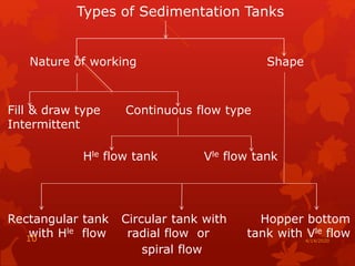
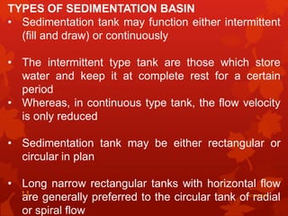
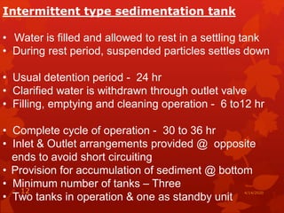
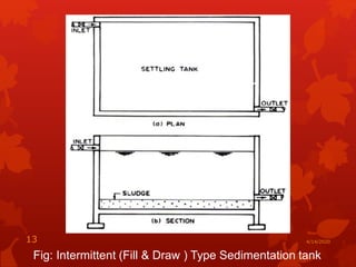
Sedimentation
Theory, settling tanks, types, design, concept
of plate and tube settlers.
Dr. Dayananda H S
Professor & Head
Department of Civil Engineering
VVCE, Mysore
4/14/20201
Sedimentation Defined
The process of separating the suspended particles from
water by gravitational settling is known as
“Sedimentation”
In other words, under the influence of gravity, the
particles with mass density higher than that of water
starts moving down
Principle involved
• The specific gravity of suspended particles in water
ranges between 1.03 for flocculated mud particles
and 2.65 for discrete particles
• These particles remain in suspension and when the
velocity of water flow is reduced or retarded, they
tend to settle down at the bottom
• The basin in which flow of water is retarded is known
as sedimentation tank or settling tank or clarifier
4/14/20202
• Sedimentation is usually employed as a preliminary
process to reduce heavy sediment loads for
subsequent treatment process such as coagulation
and filtration
• Sedimentation is the most common separation
technique falling under the unit operation “Solids
transfer”
• Sedimentation tanks are also known as settling tank
or clarifier
• Sedimentation tanks are designed to reduce the
velocity of flow of water so as to permit the
suspended solids to settle out of water by gravity
4/14/20203
TYPES OF SEDIMENTATION
1. Plain sedimentation (Unit operation) and
2. Chemically assisted sedimentation or
clarification (Unit process)
• Plain sedimentation is a process of settling
down of solids and impurities in the raw
water to the bottom of sedimentation basin
by natural gravity force alone (physical force
predominates), no chemical is added
• Sedimentation falls under the category- Type
I settling or Discrete settling
• This method - cheaper and commonly used
in all filtration and purification system of
water
4/14/20204
2. Chemically assisted sedimentation or
clarification
• In this unit process, chemicals are added to
water and thoroughly mixed
• After mixing, the suspended solids and other
impurities stick together and form flocs
• On slow agitation, microflocs get
agglomerated to macro flocs and settles
down at bottom of the basin
• In general, this type of sedimentation is
mostly adopted
4/14/20205
Factors influencing sedimentation
• Velocity of flow: more length and less velocity
- more efficiency
• Viscosity, density & temperature of water
- inversely proportional
• Size, shape, & density nature of particle –
discrete or flocculent
• Inlet and outlet arrangements – short
circuiting
• Detention period and
• Effective depth of settling zone
4/14/20206
Terminology
Detention period: It is defined as the average
theoretical time required for the water to pass
between the inlet and outlet of a settling tank
Or
In other words, it is the average time for which
the water is detained in the tank
4/14/20207
• If ‘V’ is the volume of the tank
Q is the discharge rate and
to is the detention period,
• We have, to = V/Q = LBH/Q
• Detention period depends upon the type of
suspended impurities in water
• Varies between 4-8 hours for plain
sedimentation tank
• Unless otherwise specified, it is based on
average flow 4/14/20208
Surface Overflow rate or Overflow rate or
Surface loading
• The quantity of water passing per hour (or
per day) per unit horizontal area is known as
the Surface overflow rate or overflow
rate or surface loading
• Surface loading rate or tank loading and the
settling velocity are numerically equal
(provided adjustment for units is made)
• Vs = Q/A = Surface loading
4/14/20209
Types of Sedimentation Tanks
Nature of working Shape
Fill & draw type Continuous flow type
Intermittent
Hle flow tank Vle flow tank
Rectangular tank Circular tank with Hopper bottom
with Hle flow radial flow or tank with Vle flow
spiral flow
4/14/202010
TYPES OF SEDIMENTATION BASIN
• Sedimentation tank may function either intermittent
(fill and draw) or continuously
• The intermittent type tank are those which store
water and keep it at complete rest for a certain
period
• Whereas, in continuous type tank, the flow velocity
is only reduced
• Sedimentation tank may be either rectangular or
circular in plan
• Long narrow rectangular tanks with horizontal flow
are generally preferred to the circular tank of radial
or spiral flow
4/14/202011
Intermittent type sedimentation tank
• Water is filled and allowed to rest in a settling tank
• During rest period, suspended particles settles down
• Usual detention period - 24 hr
• Clarified water is withdrawn through outlet valve
• Filling, emptying and cleaning operation - 6 to12 hr
• Complete cycle of operation - 30 to 36 hr
• Inlet & Outlet arrangements provided @ opposite
ends to avoid short circuiting
• Provision for accumulation of sediment @ bottom
• Minimum number of tanks – Three
• Two tanks in operation & one as standby unit
4/14/202012
Fig: Intermittent (Fill & Draw ) Type Sedimentation tank
4/14/202013
Continuous flow type Sedimentation
Tank
• Water keeps continuously moving through the tank
• Flow velocity is reduced by providing baffle walls &
increasing length of travel
• This enables suspended particles to settle down @
bottom before it reaches the outlet
• Velocity is so adjusted that time taken by particle to
travel from one end to other end of tank is slightly
more than that required for settlement of particle
• Permissible maximum velocity - 0.30m/sec
• Flush valve provided for cleaning and removal of silt
@ regular intervals
4/14/202014
‘Up and down’ Baffle tank
Fig: ‘Around the end’ Baffle tank
4/14/202015
Inlet & Outlet arrangements
• Inlet & Outlet arrangements are so designed to cause
minimum disturbance at inlet and outlet of the tank
• As far as possible, the water is uniformly distributed across
the width and depth of tank
• Fresh water is mixed with water already in the tank to
prevent density currents
• Minimize large scale turbulence
• Initiate longitudinal or radial flow so as to achieve high
removal efficiency
• Each inlet opening must face a baffle
• Velocity of flow through slots - 0.2 – 0.3 m/sec 4/14/202016
4/14/202017
Types of Inlet arrangement
a. Perforated Baffle
b. Submerged orifice
c. Influent channel with bottom openings and
d. Overflow weir with Baffle
Fig: Inlet arrangements
4/14/202018
Outlet arrangements
• Consists of i) Weirs, notches or orifices
ii) Effluent trough or launder and outlet
pipe
• Weir loading rates limited to prevent high approach
velocity near the outlet
• Weirs consists of V- notches 50mm in depth &
placed 150 – 300 mm c/c with baffle provided in
front of weir to avoid floating matter escaping into
outlet
• Proper design of inlets and outlets is necessary to
avoid short circuiting through basin
4/14/202019
Fig: Outlet arrangements
4/14/202020
Design elements of continuous flow Sedimentation
tank
i) Detention time and displacement efficiency
ii) Overflow rate and surface loading
iii) Basin dimensions
iv) Inlet and outlet arrangements and
v) Sludge removal devices
4/14/202021
Design criteria for sedimentation tanks
• Detention time - 3 to 4 hr ( based on depth &
overflow rate
• Depth of water in basin - 3 to 4.5 m
• Displacement velocity of water - 0.3m/sec
• Surface loading rate - 24 to 36 m3/m 2/ day
• Weir loading rate - 200 to 300 m3/m 2/ day
• Sludge storage capacity - 25% of total volume
• Floor slope - 1 in 12 for mechanical scraper
• Time taken for one revolution – 45 to 80 min
• Velocity of water in outlet - ≤ 0.4m/s
• V-notch: 50mm deep and 150 - 300mm c/c
• Diameter of circular tank - ≤ 30 m
• Length to Breadth ratio for rectangular tank- 4:1
4/14/202022
Short Circuiting
Short circuiting is caused due to
• Eddy currents set up by the inertia of the incoming
fluid
• Surface currents induced due to wind in open tanks
• Vertical convection currents due to thermal gradient
along the depth of the tank
• Density currents causing cold & heavy water to
under run the basin & warm or light water to flow
across it’s surface
• Due to difference in velocity, higher inlet level,
difference in density due to change in temperature
and salt concentration
4/14/202023
• In ideal Settling basin, displacement is steady
& uniform
• Each unit volume of fluid is retained for time,
to = C/Q
• Even in well designed tank, however some of
the inflow reaches the outlet in less than the
theoretical detention time & sometimes much
longer also
4/14/202024
RECTANGULAR v/s CIRCULAR SEDIMENTATION
BASIN
• Rectangular basins are the simplest design &
usually found in large-scale water treatment plants
• Rectangular basins have of advantages -
predictability, cost-effectiveness & low maintenance
• It is the least likely to short-circuit, especially if the
length is at least twice the width
• Only disadvantage - large extent of land area
required
• Circular sedimentation basins with horizontal flow
are often known as clarifiers
• Circular basin disadvantage- short-circuiting
problems 4/14/202025
Plate settler (Shallow depth sedimentation)
• The plate and tube settler technology was
developed to improve the settling efficiency of
smaller particles
• It is clear from Hazen’s theory that the
removal of settleable solids is primarily a
function of the surface area of the basin and
not dependent on depth
• Shallow depth sedimentation - introducing
false bottoms or horizontal trays in the
sedimentation tank, dividing the tank height
into compartments
• It is done to reduce the depth and to provide
multiple surface areas
4/14/202026
• Such an arrangement increases the surface
area, thereby reducing the surface overflow
rate (VH) and resulting in more particle
settlement
Drawbacks
• The introduction of wide shallow trays at
regular intervals gives rise to problems of
unstable hydraulic conditions and
• Difficulties in operation of mechanical sludge
removal equipment
4/14/202027
Tube settlers
• Tube settlers use tubes of 25-50mm
diameter, having large wetted perimeter
relative to the wetted area
• It provides laminar flow conditions and low
surface loading rate for sedimentation
• Two configurations of tube settlers are used
i) Horizontal tube settler and
ii) Steeply inclined tube settler
4/14/202028
Fig: Horizontal and inclined Tube settler 4/14/202029
Horizontal tube settler
• Black colored, 1.5mm thick A C pipes or
plastic tubes of square, rectangular, circular
or hexagonal shapes are used
• A large number of such tubes of 50mm x
50mm or smaller in size of height 1m are
placed together side by side to make a
bundle of rectangular or circular or square
shape to form a module
• The height of the module may be of the
order of 1m
• Figure in the previous slide shows a
horizontal tube settler in which the tubes
are inclined slightly by 5° in the direction of
flow
4/14/202030
• The sludge settled in the tube is drained by the last
portion of the filter back wash
• Second configuration shows deeply inclined tube
settler made of plastic baffles inclined at 60° to the
horizontal located between thin sheets of plastics
• The 60° angle inclination permits accumulated sludge
to slide down the tubes
• The settled sludge is conveyed to a sludge collector
zone
• Tube settlers provide excellent clarification with
detention period of ≤ 10 minutes
4/14/202031
4/14/202032
FAQ
1. Define overflow rate and detention period for
plain sedimentation tank.
2. Explain the sedimentation process in water
treatment.
3. Show mathematically that the surface loading
and not the depth is a measure of the efficiency
of a settling basin.
4. Sketch the various types of inlets and outlets
adopted in sedimentation basins.
5. Mention the design criteria for continuous flow
sedimentation tanks.
6. Write a note on plate settlers and tube settlers.

Plain sedimentation

  • 1.
    Sedimentation Theory, settling tanks,types, design, concept of plate and tube settlers. Dr. Dayananda H S Professor & Head Department of Civil Engineering VVCE, Mysore 4/14/20201
  • 2.
    Sedimentation Defined The processof separating the suspended particles from water by gravitational settling is known as “Sedimentation” In other words, under the influence of gravity, the particles with mass density higher than that of water starts moving down Principle involved • The specific gravity of suspended particles in water ranges between 1.03 for flocculated mud particles and 2.65 for discrete particles • These particles remain in suspension and when the velocity of water flow is reduced or retarded, they tend to settle down at the bottom • The basin in which flow of water is retarded is known as sedimentation tank or settling tank or clarifier 4/14/20202
  • 3.
    • Sedimentation isusually employed as a preliminary process to reduce heavy sediment loads for subsequent treatment process such as coagulation and filtration • Sedimentation is the most common separation technique falling under the unit operation “Solids transfer” • Sedimentation tanks are also known as settling tank or clarifier • Sedimentation tanks are designed to reduce the velocity of flow of water so as to permit the suspended solids to settle out of water by gravity 4/14/20203
  • 4.
    TYPES OF SEDIMENTATION 1.Plain sedimentation (Unit operation) and 2. Chemically assisted sedimentation or clarification (Unit process) • Plain sedimentation is a process of settling down of solids and impurities in the raw water to the bottom of sedimentation basin by natural gravity force alone (physical force predominates), no chemical is added • Sedimentation falls under the category- Type I settling or Discrete settling • This method - cheaper and commonly used in all filtration and purification system of water 4/14/20204
  • 5.
    2. Chemically assistedsedimentation or clarification • In this unit process, chemicals are added to water and thoroughly mixed • After mixing, the suspended solids and other impurities stick together and form flocs • On slow agitation, microflocs get agglomerated to macro flocs and settles down at bottom of the basin • In general, this type of sedimentation is mostly adopted 4/14/20205
  • 6.
    Factors influencing sedimentation •Velocity of flow: more length and less velocity - more efficiency • Viscosity, density & temperature of water - inversely proportional • Size, shape, & density nature of particle – discrete or flocculent • Inlet and outlet arrangements – short circuiting • Detention period and • Effective depth of settling zone 4/14/20206
  • 7.
    Terminology Detention period: Itis defined as the average theoretical time required for the water to pass between the inlet and outlet of a settling tank Or In other words, it is the average time for which the water is detained in the tank 4/14/20207
  • 8.
    • If ‘V’is the volume of the tank Q is the discharge rate and to is the detention period, • We have, to = V/Q = LBH/Q • Detention period depends upon the type of suspended impurities in water • Varies between 4-8 hours for plain sedimentation tank • Unless otherwise specified, it is based on average flow 4/14/20208
  • 9.
    Surface Overflow rateor Overflow rate or Surface loading • The quantity of water passing per hour (or per day) per unit horizontal area is known as the Surface overflow rate or overflow rate or surface loading • Surface loading rate or tank loading and the settling velocity are numerically equal (provided adjustment for units is made) • Vs = Q/A = Surface loading 4/14/20209
  • 10.
    Types of SedimentationTanks Nature of working Shape Fill & draw type Continuous flow type Intermittent Hle flow tank Vle flow tank Rectangular tank Circular tank with Hopper bottom with Hle flow radial flow or tank with Vle flow spiral flow 4/14/202010
  • 11.
    TYPES OF SEDIMENTATIONBASIN • Sedimentation tank may function either intermittent (fill and draw) or continuously • The intermittent type tank are those which store water and keep it at complete rest for a certain period • Whereas, in continuous type tank, the flow velocity is only reduced • Sedimentation tank may be either rectangular or circular in plan • Long narrow rectangular tanks with horizontal flow are generally preferred to the circular tank of radial or spiral flow 4/14/202011
  • 12.
    Intermittent type sedimentationtank • Water is filled and allowed to rest in a settling tank • During rest period, suspended particles settles down • Usual detention period - 24 hr • Clarified water is withdrawn through outlet valve • Filling, emptying and cleaning operation - 6 to12 hr • Complete cycle of operation - 30 to 36 hr • Inlet & Outlet arrangements provided @ opposite ends to avoid short circuiting • Provision for accumulation of sediment @ bottom • Minimum number of tanks – Three • Two tanks in operation & one as standby unit 4/14/202012
  • 13.
    Fig: Intermittent (Fill& Draw ) Type Sedimentation tank 4/14/202013
  • 14.
    Continuous flow typeSedimentation Tank • Water keeps continuously moving through the tank • Flow velocity is reduced by providing baffle walls & increasing length of travel • This enables suspended particles to settle down @ bottom before it reaches the outlet • Velocity is so adjusted that time taken by particle to travel from one end to other end of tank is slightly more than that required for settlement of particle • Permissible maximum velocity - 0.30m/sec • Flush valve provided for cleaning and removal of silt @ regular intervals 4/14/202014
  • 15.
    ‘Up and down’Baffle tank Fig: ‘Around the end’ Baffle tank 4/14/202015
  • 16.
    Inlet & Outletarrangements • Inlet & Outlet arrangements are so designed to cause minimum disturbance at inlet and outlet of the tank • As far as possible, the water is uniformly distributed across the width and depth of tank • Fresh water is mixed with water already in the tank to prevent density currents • Minimize large scale turbulence • Initiate longitudinal or radial flow so as to achieve high removal efficiency • Each inlet opening must face a baffle • Velocity of flow through slots - 0.2 – 0.3 m/sec 4/14/202016
  • 17.
    4/14/202017 Types of Inletarrangement a. Perforated Baffle b. Submerged orifice c. Influent channel with bottom openings and d. Overflow weir with Baffle
  • 18.
  • 19.
    Outlet arrangements • Consistsof i) Weirs, notches or orifices ii) Effluent trough or launder and outlet pipe • Weir loading rates limited to prevent high approach velocity near the outlet • Weirs consists of V- notches 50mm in depth & placed 150 – 300 mm c/c with baffle provided in front of weir to avoid floating matter escaping into outlet • Proper design of inlets and outlets is necessary to avoid short circuiting through basin 4/14/202019
  • 20.
  • 21.
    Design elements ofcontinuous flow Sedimentation tank i) Detention time and displacement efficiency ii) Overflow rate and surface loading iii) Basin dimensions iv) Inlet and outlet arrangements and v) Sludge removal devices 4/14/202021
  • 22.
    Design criteria forsedimentation tanks • Detention time - 3 to 4 hr ( based on depth & overflow rate • Depth of water in basin - 3 to 4.5 m • Displacement velocity of water - 0.3m/sec • Surface loading rate - 24 to 36 m3/m 2/ day • Weir loading rate - 200 to 300 m3/m 2/ day • Sludge storage capacity - 25% of total volume • Floor slope - 1 in 12 for mechanical scraper • Time taken for one revolution – 45 to 80 min • Velocity of water in outlet - ≤ 0.4m/s • V-notch: 50mm deep and 150 - 300mm c/c • Diameter of circular tank - ≤ 30 m • Length to Breadth ratio for rectangular tank- 4:1 4/14/202022
  • 23.
    Short Circuiting Short circuitingis caused due to • Eddy currents set up by the inertia of the incoming fluid • Surface currents induced due to wind in open tanks • Vertical convection currents due to thermal gradient along the depth of the tank • Density currents causing cold & heavy water to under run the basin & warm or light water to flow across it’s surface • Due to difference in velocity, higher inlet level, difference in density due to change in temperature and salt concentration 4/14/202023
  • 24.
    • In idealSettling basin, displacement is steady & uniform • Each unit volume of fluid is retained for time, to = C/Q • Even in well designed tank, however some of the inflow reaches the outlet in less than the theoretical detention time & sometimes much longer also 4/14/202024
  • 25.
    RECTANGULAR v/s CIRCULARSEDIMENTATION BASIN • Rectangular basins are the simplest design & usually found in large-scale water treatment plants • Rectangular basins have of advantages - predictability, cost-effectiveness & low maintenance • It is the least likely to short-circuit, especially if the length is at least twice the width • Only disadvantage - large extent of land area required • Circular sedimentation basins with horizontal flow are often known as clarifiers • Circular basin disadvantage- short-circuiting problems 4/14/202025
  • 26.
    Plate settler (Shallowdepth sedimentation) • The plate and tube settler technology was developed to improve the settling efficiency of smaller particles • It is clear from Hazen’s theory that the removal of settleable solids is primarily a function of the surface area of the basin and not dependent on depth • Shallow depth sedimentation - introducing false bottoms or horizontal trays in the sedimentation tank, dividing the tank height into compartments • It is done to reduce the depth and to provide multiple surface areas 4/14/202026
  • 27.
    • Such anarrangement increases the surface area, thereby reducing the surface overflow rate (VH) and resulting in more particle settlement Drawbacks • The introduction of wide shallow trays at regular intervals gives rise to problems of unstable hydraulic conditions and • Difficulties in operation of mechanical sludge removal equipment 4/14/202027
  • 28.
    Tube settlers • Tubesettlers use tubes of 25-50mm diameter, having large wetted perimeter relative to the wetted area • It provides laminar flow conditions and low surface loading rate for sedimentation • Two configurations of tube settlers are used i) Horizontal tube settler and ii) Steeply inclined tube settler 4/14/202028
  • 29.
    Fig: Horizontal andinclined Tube settler 4/14/202029
  • 30.
    Horizontal tube settler •Black colored, 1.5mm thick A C pipes or plastic tubes of square, rectangular, circular or hexagonal shapes are used • A large number of such tubes of 50mm x 50mm or smaller in size of height 1m are placed together side by side to make a bundle of rectangular or circular or square shape to form a module • The height of the module may be of the order of 1m • Figure in the previous slide shows a horizontal tube settler in which the tubes are inclined slightly by 5° in the direction of flow 4/14/202030
  • 31.
    • The sludgesettled in the tube is drained by the last portion of the filter back wash • Second configuration shows deeply inclined tube settler made of plastic baffles inclined at 60° to the horizontal located between thin sheets of plastics • The 60° angle inclination permits accumulated sludge to slide down the tubes • The settled sludge is conveyed to a sludge collector zone • Tube settlers provide excellent clarification with detention period of ≤ 10 minutes 4/14/202031
  • 32.
    4/14/202032 FAQ 1. Define overflowrate and detention period for plain sedimentation tank. 2. Explain the sedimentation process in water treatment. 3. Show mathematically that the surface loading and not the depth is a measure of the efficiency of a settling basin. 4. Sketch the various types of inlets and outlets adopted in sedimentation basins. 5. Mention the design criteria for continuous flow sedimentation tanks. 6. Write a note on plate settlers and tube settlers.