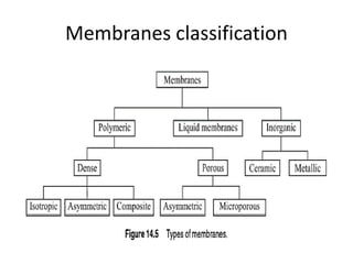
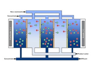
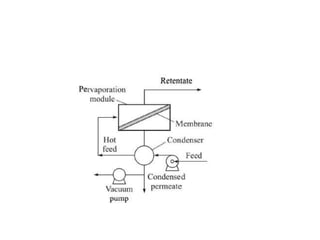
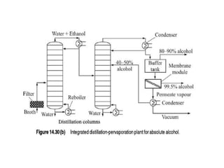
Membrane Separation Process
Mass Transfer 2
B.Tech. 3rd Year
Instructor
U. K. Arun Kumar
Introduction
• Membrane: is a thin barrier, placed between
two phases or mediums,
• It allows one or more species to selectively pass
from one medium to the other while retaining
the rest.
• It is done by a driving force.
• Membranes used for separation of mixtures are
called semi-permeable.
Classification - Membrane Separation Processes
Driving force for MSP
– Pressure difference
– Concentration difference
• Pressure Driven Processes
– Reverse Osmosis (RO)
– Nanofiltration (NF)
– Ultrafiltration (UF)
– Microfiltration (MF)
• Concentration Gradient Driven Membrane
process:
– Dialysis
– Membrane Extraction
– Electrodialysis
– Pervaporation
MSP – Advantages & Disadvantages
• Advantages
– Inherently simple
– Moderate operating temperature for high value
heat sensitive substances
– No change of phase occurs (except in
pervaporation)
– Same basic principles apply to most MSP
MSP - Disadvantages
• Membrane fouling and resultant flux decline
• Polymeric membranes have limited chemical
resistance to organic solvents
• A high degree of separation may not be
possible for many mixtures.
Desired properties of a membrane
• A good membrane should have
– Good permeability
– High selectivity
– Chemical stability and compatibility
– Mechanical strength
– Resistance to fouling and adsorption
– Amenability to casting of a thin film
– Suitability for fabrication of a module
Membranes classification
• Polymeric membrane
– Dense or non porous membrane and Porous
membrane
• Dense or Non porous Membrane
– Isotropic or symmetric membrane
– Asymmetric membrane
– Composite membrane
• Porous Membrane
– Asymmetric membrane
– Microporous membrane
Dense Membranes
• A dense or non-porous membrane is a thin film
that allows selective passage of one or more
components of a mixture.
• No pores are present in the physical sense
• Permeating compound - dissolves at the
membrane surface
• Diffuses through the intermolecular space or free
volume within membrane
• Leaves at the opposite surface as permeate or
product
• Used – RO, gas separation process, pervoporation
• A dense membrane may have an asymmetric
or a composite structure.
• Asymmetric Membrane
– An asymmetric dense membrane has a thin dense
or non-porous permselective layer on a porous
substructure.
– The dense layer allows selective permeation (i.e.
perm-selective)
– The porous substructure offers necessary
mechanical strength to the membrane
• Allows high permeate flux
Symmetric or Isotropic Microporous
Membrane
• Symmetric microporous membranes are
functionally similar to conventional filters.
• In symmetric membrane the materials are
same
• But differ in their pore size and thickness
• Filters – separate relatively coarse particles in
suspension
• Microporous membranes: separate very fine
particles or colloids or even dissolved solutes
• Membranes are thinner than filters
• Microporous symmetric membranes
• have interconnected pores
• High porosity
• Used for microfiltration
• Pore size range from 0.1 – 10 μm.
• Particles >10 μm are rejected completely.
• Those smaller than <0.1 μm smallest pore size
freely pass through the pores.
Asymmetric Membranes
• Membrane should be as thin as possible for
high permeation flux
• Should have reasonable mechanical strength
and defect free.
• If membranes are too thin and mechanical
weak –
– Difficult to handle
– Develop pin-holes
• Practically impossible to have membrane <20
μm
• To overcome this problem
• Asymmetric membranes are made to contain
– A thin permselective layer (0.1 to 1.0 μm)
– Supported on a highly porous substructure
• The thin layer may be non-porous (RO
membrane) or with very fine pores (UF
membrane)
• Entire material is an integral part of same
material
Composite Membrane
• Composite membranes are functionally similar
to asymmetric membranes
• It contains
– A porous or dense, thin permselective upper layer
– Cast on a thick mechanically strong support.
• The thin layer and the support are made up
of different materials
Electrically Charged Membranes
• They have ionic groups attached to the
membrane
• Forming fixed charged sites.
• In PEM fuel cell, the Nafion membrane is used
• Perfluoro ion exchange membrane has SO3
-
groups on a PTFE backbone
• This group give negatively charged fixed sites
• The cation can move freely within the
membrane matrix
• If the membrane contains a negative group
attached - conducts the cations freely
• The fixed charges repel the negative charges
and does not allow anions.
• Hence the name cation exchange membrane
• If the fixed charges are positive ,
• The membrane is called anion-exchange-
membrane.
• Pressure driven membrane processes for
liquid separation
• Micro-Filtration
• Ultra-Filtration
• Nano-Filtration
• Reverse Osmosis
Microfiltration
• Microfiltration refers to separation of fine
particles and colloids from a liquid or
particulates from a gas
• It uses porous membrane having pore sizes
range 100 to 104 nm or (0.1 to 10 μm) .
• Traditionally used for separation of
microorganisms.
• Separation of yeast from fermentation broth
• 1G – MF membranes were made from
nitrocellulose.
• Separation occurs by sieving mechanism
• low pressure difference about 2 bar.
• Two types of flow and filtration arrangements
are –
– Cross flow filtration
– Dead-end filtration.
• Cross-flow filtration.
– Feed flows parallel to membrane surface
– Most of particles or solute are swept away with
the flowing feed liquid
– A part of liquid is re-circulated if required.
• Dead-end filtration
– Feed flow is normal to membrane surface
– Retained particles or solute form a cake on
membrane surface.
– Cake growth offers filtration resistance
Applications
• 1. Making small-scale lab separations for
microbiological analysis – of soft drinks,
wines, pharmaceutical products.
• Sterilization and clarification in food and
beverage, clarification of cheese etc.
• Harvesting of cells from a fermentation broth
• Detection and analysis of particulate
contaminants in air.
Theoretical principles
• In MF, the objective is to concentrate a
suspension - by forcing the liquid through
the pores
• Calculating solvent flux in membrane module
is essential for design of MF device
• The flux may be expressed by Darcys law
• K’ – is a constant
• If the flow of the fluid through the pore is
laminar,
• Hagen-Poiseulle equation can be used
• Sometime the membrane structure
resembles like a very thin packed bed (with
void spaces)
• The pressure drop relation for such a
membrane is give by Kozeny-Karman
equation
Ultra Filtration (UF)
• Separation or concentration of a large molecular
weight solute or a colloidal suspension
• Approximate mol. wt. range 1000 to 80,000
Dalton (unit of mass equivalent to H atom)
• Membrane pores size - range 1 to 100 nm.
• Driving force for UF is - ΔP
• Separation occurs by sieving mechanism.
• Separates larger molecules from smaller ones
which pass through the membrane
• Application of Ultra Filtration
Application of UF
Paint
Recovery
Latex
Recovery
Water
treatment
Separation of
oil – water
Paper
industry
Configuration of a UF unit
• Since a single membrane module does not
provide large area,
• A number of modules are used in parallels
depending on feed rate.
• Two configurations are used
– Recycle configuration
– Tapered configuration
Recycle configuration
• A part of the retentate is reclycled back to the inlet
of the module
• To achieve higher concentration of rententate
• Increases cross flow velocity
• Reduces membrane
fouling
Tapered Configuration
• Modules are arranged in a parallel-series
pattern
• Retentate volume decreases after liquid
passes through a module
• Therefore, a lesser number of modules are
provided in successive stages.
Reverse Osmosis
• When aqueous solution is kept separated
from water by a semi-permeable membrane
in two compartment cell,
• Water diffuses through the membrane into
higher concentration compartment.
• This is due to the difference in chemical
potential of water in two compartments.
• Chemical potential of pure water is larger
than water containing a dissolved solute.
• When the level of solution is maintained at a
certain elevated position, the flow of solute to
higher concentration side stops.
• This condition is called osmotic equilibrium.
• The extra pressure due to the elevated level of
solution is –osmotic pressure (π)
• The chemical potential of water in a solution
increases if it is maintained at an elevated
pressure.
• When an extra pressure higher than the osmotic
pressure is applied, the chemical potential of
water in solution becomes larger than pure
water.
• So that , water flows from solution to the pure
water side.
• This is reverse osmosis.
• Driving force: difference in chemical potential of
water on both sides.
• RO is most important technique for desalination
of brackish (1000 – 5000 ppm salt)
• Or sea water (35,000 ppm or 3.5 % salt)
• Commercial exploitation was not possible
until the 1960s
• The development of high flux, asymmetric
cellulose acetate membrane by (Loeb and
Sourirajan, 1963) made it commercially
possible.
• Over 12,500 industrial scale desalination
plants are operating worldwide.
• With an average production of 23 milliion m3
per day of drinking water
Models for water/solute transport in RO –
Solution-Diffusion Model
• This model assumes that sorption of both the
solute and the solvent occurs at the upstream
section of the membrane
• Followed by diffusion through the non-porous
and homogeneous permselective layer
• And exits the membrane at the other side of
membrane
• Diffusion flux of solvent is given by
• The change in chemical potential of the
solvent is given by
• Substituting equation 2, in equation 1. gives
• Δμm - is the difference in chemical potential
across the homogeneous membrane layer of
thickness, lm
• Expressing the above equation in terms of
measurable quantities
• The overall equation, after substitution
becomes,
• For the salt (flux), - i.e., solute flux
• Contribution of pressure towards chemical
potential difference is negligible,
• So the salt flux is viewed as diffusive and is
expressed as
• Maximum rejection of NaCl is about 70 %
• Permeation flux: 0.1 to 1 m3/m2.day
• Application:
• Water reclamation
• Food industries – concentration of dextrose
syrup
• Chemical: metal recovery, recovery of textile
dyes, cleaning paper mill efflueents
Concentration Driven Process
• Dialysis - is diffusional transport of one or
more dissolved species – through a thin
permselective barrier.
• The membrane is place between two aqueous
solutions at different concentrations
• Separation is by concentration driving force
• No bulk flow of solvent or solution through
membrane
• Since smaller molecules diffuse faster than
larger ones,
• Dialysis separate such molecules from
solution.
• NaOH (17-20 %) in the viscose liquor can be
recovered as 9-10 % solutions by dialysis
• A dialysis unit is called dialyser.
• The feed-side liquid leaving the unit is called
dialysate (rententate)
• And that leaving the permeate side is
diffusate (permeate)
• A membrane that swells substantially in
contact with the solvent is selected,
• Because the process involves diffusion
through dense membranes
• Swelling of a polymer increases the spaces
between the polymer chains and facilitates
diffusional motion of molecules through it.
• Applications
• In medical purposes-haemodialysis
• Dialysis offers a passive envirionment for
transport solutions are not in direct contact
• No pressure is applied as in RO
• Many breweries use dialysis to reduce alchol
content of beer
Electrodialysis
• Electrodialysis (ED) is a process of removal of
salts from an aqueous solution
• By transport through an electrically charged
membrane.
• Cell is divided into a number of
compartments by placing pieces of a cation
exchange membrane and an anion exchange
membrane alternatively
• At the two ends are placed a cathode and an
anode connected to a DC power supply
• Example NaCl,
• Na+ ions pass through the cation-exchange
membrane that has a fixed negative charges
• But anions are rejected
• Anion exchange membrane allows Cl- ions to
pass through.
• Thus the solution passing through the
compartment are depleted of the salt.
• The adjacent compartments get enriched in
the salt.
• Desalinated water and concentrated brine
leave from adjacent compartments.
• Applied electrical potential is the driving force
of the process.
• It is widely used for desalination of brackish
water as an alternative to RO.
Pervaporation
• Pervaporation combines - permeation of one or
more species and its subsequent vaporization.
• Pervaporation: permeation + vaporization
• A component in the feed, that has large affinity
for the membrane gets sorbed (dissolved) on
the feed-side membrane
• The solute then – diffused through the
membrane
• Vaporizes at the product side of the membrane
• Vaporization occurs at the product side under
vacuum
• The vapour product – having a target
compound at a much larger conc. than in the
feed is condensed and recovered as liquid.
• Pervaporation cannot be an alternative for
the conventional processes
• Like distillation and liquid extraction
• The diffusional flux through a membrane is
generally low
• Also right membrane that would provide high
flux and satisfactory separation factor is not
always available.
• Industrial application:
– Preparation of absolute alcohol
– Dehydration of solvents
Salt and Light
• “You are the salt of the earth.
• But if the salt loses its saltiness, how can it be
made salty again? It is no longer good for
anything, except to be thrown out and trampled
underfoot.
• You are the light of the world.
• A town built on a hill cannot be hidden. Neither
do people light a lamp and put it under a bowl.
Instead they put it on its stand, and it gives light
to everyone in the house

Membrane separation process

  • 1.
    Membrane Separation Process MassTransfer 2 B.Tech. 3rd Year Instructor U. K. Arun Kumar
  • 2.
    Introduction • Membrane: isa thin barrier, placed between two phases or mediums, • It allows one or more species to selectively pass from one medium to the other while retaining the rest. • It is done by a driving force. • Membranes used for separation of mixtures are called semi-permeable.
  • 4.
    Classification - MembraneSeparation Processes Driving force for MSP – Pressure difference – Concentration difference • Pressure Driven Processes – Reverse Osmosis (RO) – Nanofiltration (NF) – Ultrafiltration (UF) – Microfiltration (MF)
  • 5.
    • Concentration GradientDriven Membrane process: – Dialysis – Membrane Extraction – Electrodialysis – Pervaporation
  • 6.
    MSP – Advantages& Disadvantages • Advantages – Inherently simple – Moderate operating temperature for high value heat sensitive substances – No change of phase occurs (except in pervaporation) – Same basic principles apply to most MSP
  • 7.
    MSP - Disadvantages •Membrane fouling and resultant flux decline • Polymeric membranes have limited chemical resistance to organic solvents • A high degree of separation may not be possible for many mixtures.
  • 8.
    Desired properties ofa membrane • A good membrane should have – Good permeability – High selectivity – Chemical stability and compatibility – Mechanical strength – Resistance to fouling and adsorption – Amenability to casting of a thin film – Suitability for fabrication of a module
  • 9.
  • 10.
    • Polymeric membrane –Dense or non porous membrane and Porous membrane • Dense or Non porous Membrane – Isotropic or symmetric membrane – Asymmetric membrane – Composite membrane • Porous Membrane – Asymmetric membrane – Microporous membrane
  • 11.
    Dense Membranes • Adense or non-porous membrane is a thin film that allows selective passage of one or more components of a mixture. • No pores are present in the physical sense • Permeating compound - dissolves at the membrane surface • Diffuses through the intermolecular space or free volume within membrane • Leaves at the opposite surface as permeate or product • Used – RO, gas separation process, pervoporation
  • 12.
    • A densemembrane may have an asymmetric or a composite structure. • Asymmetric Membrane – An asymmetric dense membrane has a thin dense or non-porous permselective layer on a porous substructure. – The dense layer allows selective permeation (i.e. perm-selective) – The porous substructure offers necessary mechanical strength to the membrane • Allows high permeate flux
  • 13.
    Symmetric or IsotropicMicroporous Membrane • Symmetric microporous membranes are functionally similar to conventional filters. • In symmetric membrane the materials are same • But differ in their pore size and thickness • Filters – separate relatively coarse particles in suspension
  • 14.
    • Microporous membranes:separate very fine particles or colloids or even dissolved solutes • Membranes are thinner than filters • Microporous symmetric membranes • have interconnected pores • High porosity • Used for microfiltration • Pore size range from 0.1 – 10 μm. • Particles >10 μm are rejected completely. • Those smaller than <0.1 μm smallest pore size freely pass through the pores.
  • 15.
    Asymmetric Membranes • Membraneshould be as thin as possible for high permeation flux • Should have reasonable mechanical strength and defect free. • If membranes are too thin and mechanical weak – – Difficult to handle – Develop pin-holes • Practically impossible to have membrane <20 μm
  • 16.
    • To overcomethis problem • Asymmetric membranes are made to contain – A thin permselective layer (0.1 to 1.0 μm) – Supported on a highly porous substructure • The thin layer may be non-porous (RO membrane) or with very fine pores (UF membrane) • Entire material is an integral part of same material
  • 17.
    Composite Membrane • Compositemembranes are functionally similar to asymmetric membranes • It contains – A porous or dense, thin permselective upper layer – Cast on a thick mechanically strong support. • The thin layer and the support are made up of different materials
  • 19.
    Electrically Charged Membranes •They have ionic groups attached to the membrane • Forming fixed charged sites. • In PEM fuel cell, the Nafion membrane is used • Perfluoro ion exchange membrane has SO3 - groups on a PTFE backbone • This group give negatively charged fixed sites • The cation can move freely within the membrane matrix
  • 20.
    • If themembrane contains a negative group attached - conducts the cations freely • The fixed charges repel the negative charges and does not allow anions. • Hence the name cation exchange membrane • If the fixed charges are positive , • The membrane is called anion-exchange- membrane.
  • 21.
    • Pressure drivenmembrane processes for liquid separation • Micro-Filtration • Ultra-Filtration • Nano-Filtration • Reverse Osmosis
  • 22.
    Microfiltration • Microfiltration refersto separation of fine particles and colloids from a liquid or particulates from a gas • It uses porous membrane having pore sizes range 100 to 104 nm or (0.1 to 10 μm) . • Traditionally used for separation of microorganisms. • Separation of yeast from fermentation broth
  • 24.
    • 1G –MF membranes were made from nitrocellulose. • Separation occurs by sieving mechanism • low pressure difference about 2 bar. • Two types of flow and filtration arrangements are – – Cross flow filtration – Dead-end filtration.
  • 25.
    • Cross-flow filtration. –Feed flows parallel to membrane surface – Most of particles or solute are swept away with the flowing feed liquid – A part of liquid is re-circulated if required. • Dead-end filtration – Feed flow is normal to membrane surface – Retained particles or solute form a cake on membrane surface. – Cake growth offers filtration resistance
  • 28.
    Applications • 1. Makingsmall-scale lab separations for microbiological analysis – of soft drinks, wines, pharmaceutical products. • Sterilization and clarification in food and beverage, clarification of cheese etc. • Harvesting of cells from a fermentation broth • Detection and analysis of particulate contaminants in air.
  • 29.
    Theoretical principles • InMF, the objective is to concentrate a suspension - by forcing the liquid through the pores • Calculating solvent flux in membrane module is essential for design of MF device • The flux may be expressed by Darcys law • K’ – is a constant
  • 30.
    • If theflow of the fluid through the pore is laminar, • Hagen-Poiseulle equation can be used
  • 31.
    • Sometime themembrane structure resembles like a very thin packed bed (with void spaces) • The pressure drop relation for such a membrane is give by Kozeny-Karman equation
  • 32.
    Ultra Filtration (UF) •Separation or concentration of a large molecular weight solute or a colloidal suspension • Approximate mol. wt. range 1000 to 80,000 Dalton (unit of mass equivalent to H atom) • Membrane pores size - range 1 to 100 nm. • Driving force for UF is - ΔP • Separation occurs by sieving mechanism. • Separates larger molecules from smaller ones which pass through the membrane
  • 34.
    • Application ofUltra Filtration Application of UF Paint Recovery Latex Recovery Water treatment Separation of oil – water Paper industry
  • 35.
    Configuration of aUF unit • Since a single membrane module does not provide large area, • A number of modules are used in parallels depending on feed rate. • Two configurations are used – Recycle configuration – Tapered configuration
  • 36.
    Recycle configuration • Apart of the retentate is reclycled back to the inlet of the module • To achieve higher concentration of rententate • Increases cross flow velocity • Reduces membrane fouling
  • 37.
    Tapered Configuration • Modulesare arranged in a parallel-series pattern • Retentate volume decreases after liquid passes through a module • Therefore, a lesser number of modules are provided in successive stages.
  • 39.
    Reverse Osmosis • Whenaqueous solution is kept separated from water by a semi-permeable membrane in two compartment cell, • Water diffuses through the membrane into higher concentration compartment. • This is due to the difference in chemical potential of water in two compartments. • Chemical potential of pure water is larger than water containing a dissolved solute.
  • 41.
    • When thelevel of solution is maintained at a certain elevated position, the flow of solute to higher concentration side stops. • This condition is called osmotic equilibrium. • The extra pressure due to the elevated level of solution is –osmotic pressure (π) • The chemical potential of water in a solution increases if it is maintained at an elevated pressure.
  • 42.
    • When anextra pressure higher than the osmotic pressure is applied, the chemical potential of water in solution becomes larger than pure water. • So that , water flows from solution to the pure water side. • This is reverse osmosis. • Driving force: difference in chemical potential of water on both sides. • RO is most important technique for desalination of brackish (1000 – 5000 ppm salt)
  • 43.
    • Or seawater (35,000 ppm or 3.5 % salt) • Commercial exploitation was not possible until the 1960s • The development of high flux, asymmetric cellulose acetate membrane by (Loeb and Sourirajan, 1963) made it commercially possible. • Over 12,500 industrial scale desalination plants are operating worldwide. • With an average production of 23 milliion m3 per day of drinking water
  • 45.
    Models for water/solutetransport in RO – Solution-Diffusion Model • This model assumes that sorption of both the solute and the solvent occurs at the upstream section of the membrane • Followed by diffusion through the non-porous and homogeneous permselective layer • And exits the membrane at the other side of membrane
  • 46.
    • Diffusion fluxof solvent is given by • The change in chemical potential of the solvent is given by • Substituting equation 2, in equation 1. gives
  • 47.
    • Δμm -is the difference in chemical potential across the homogeneous membrane layer of thickness, lm • Expressing the above equation in terms of measurable quantities
  • 48.
    • The overallequation, after substitution becomes,
  • 49.
    • For thesalt (flux), - i.e., solute flux • Contribution of pressure towards chemical potential difference is negligible, • So the salt flux is viewed as diffusive and is expressed as
  • 50.
    • Maximum rejectionof NaCl is about 70 % • Permeation flux: 0.1 to 1 m3/m2.day • Application: • Water reclamation • Food industries – concentration of dextrose syrup • Chemical: metal recovery, recovery of textile dyes, cleaning paper mill efflueents
  • 51.
    Concentration Driven Process •Dialysis - is diffusional transport of one or more dissolved species – through a thin permselective barrier. • The membrane is place between two aqueous solutions at different concentrations • Separation is by concentration driving force • No bulk flow of solvent or solution through membrane
  • 52.
    • Since smallermolecules diffuse faster than larger ones, • Dialysis separate such molecules from solution. • NaOH (17-20 %) in the viscose liquor can be recovered as 9-10 % solutions by dialysis • A dialysis unit is called dialyser. • The feed-side liquid leaving the unit is called dialysate (rententate)
  • 53.
    • And thatleaving the permeate side is diffusate (permeate) • A membrane that swells substantially in contact with the solvent is selected, • Because the process involves diffusion through dense membranes • Swelling of a polymer increases the spaces between the polymer chains and facilitates diffusional motion of molecules through it.
  • 54.
    • Applications • Inmedical purposes-haemodialysis • Dialysis offers a passive envirionment for transport solutions are not in direct contact • No pressure is applied as in RO • Many breweries use dialysis to reduce alchol content of beer
  • 55.
    Electrodialysis • Electrodialysis (ED)is a process of removal of salts from an aqueous solution • By transport through an electrically charged membrane. • Cell is divided into a number of compartments by placing pieces of a cation exchange membrane and an anion exchange membrane alternatively
  • 56.
    • At thetwo ends are placed a cathode and an anode connected to a DC power supply • Example NaCl, • Na+ ions pass through the cation-exchange membrane that has a fixed negative charges • But anions are rejected • Anion exchange membrane allows Cl- ions to pass through. • Thus the solution passing through the compartment are depleted of the salt.
  • 57.
    • The adjacentcompartments get enriched in the salt. • Desalinated water and concentrated brine leave from adjacent compartments. • Applied electrical potential is the driving force of the process. • It is widely used for desalination of brackish water as an alternative to RO.
  • 59.
    Pervaporation • Pervaporation combines- permeation of one or more species and its subsequent vaporization. • Pervaporation: permeation + vaporization • A component in the feed, that has large affinity for the membrane gets sorbed (dissolved) on the feed-side membrane • The solute then – diffused through the membrane • Vaporizes at the product side of the membrane
  • 60.
    • Vaporization occursat the product side under vacuum • The vapour product – having a target compound at a much larger conc. than in the feed is condensed and recovered as liquid. • Pervaporation cannot be an alternative for the conventional processes • Like distillation and liquid extraction • The diffusional flux through a membrane is generally low
  • 61.
    • Also rightmembrane that would provide high flux and satisfactory separation factor is not always available. • Industrial application: – Preparation of absolute alcohol – Dehydration of solvents
  • 64.
    Salt and Light •“You are the salt of the earth. • But if the salt loses its saltiness, how can it be made salty again? It is no longer good for anything, except to be thrown out and trampled underfoot. • You are the light of the world. • A town built on a hill cannot be hidden. Neither do people light a lamp and put it under a bowl. Instead they put it on its stand, and it gives light to everyone in the house