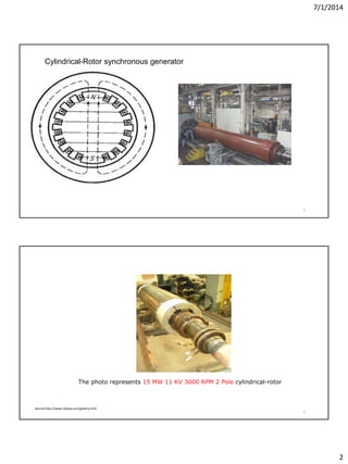
This document provides an overview of synchronous generator models for power system analysis. It discusses the steady-state model of synchronous generators, including their cylindrical and salient pole rotor constructions. Equivalent circuits are presented showing the generator internal voltage and synchronous reactance. Per-unit calculations and phasor diagrams are used to explain generator operation at different power factors and reactive power control via field excitation.

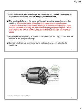
![7/1/2014
10
19
Source: http://www.youtube.com/watch?v=tiKH48EMgKE
How does alternator (synchronous generator) work ?
How does Alternator Work.mp4 (5:19 mins)
20
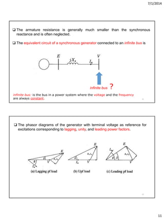
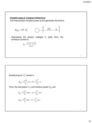
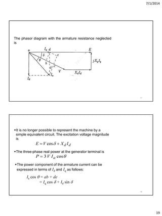
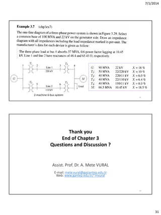
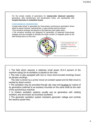
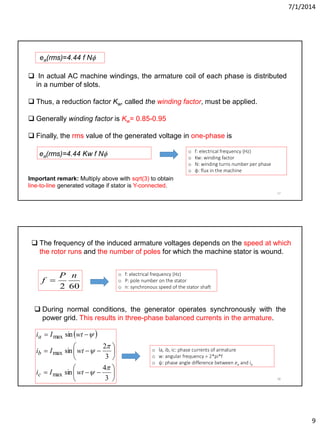
A simple per-phase model for a cylindrical rotor generator is
E=V + [Ra+ j Xs ]Ia
o V: per-phase syn. gen. Voltage after its impedance
o Ia: Per-phase armature current
o E: Per-phase internal generated voltage
o Ra: per-phase armature resistance
o Xs: Synchronous reactance](https://image.slidesharecdn.com/eee471ch36559-150528203003-lva1-app6891/85/POWER-SYSTEM-ANALYSIS-3-10-320.jpg)