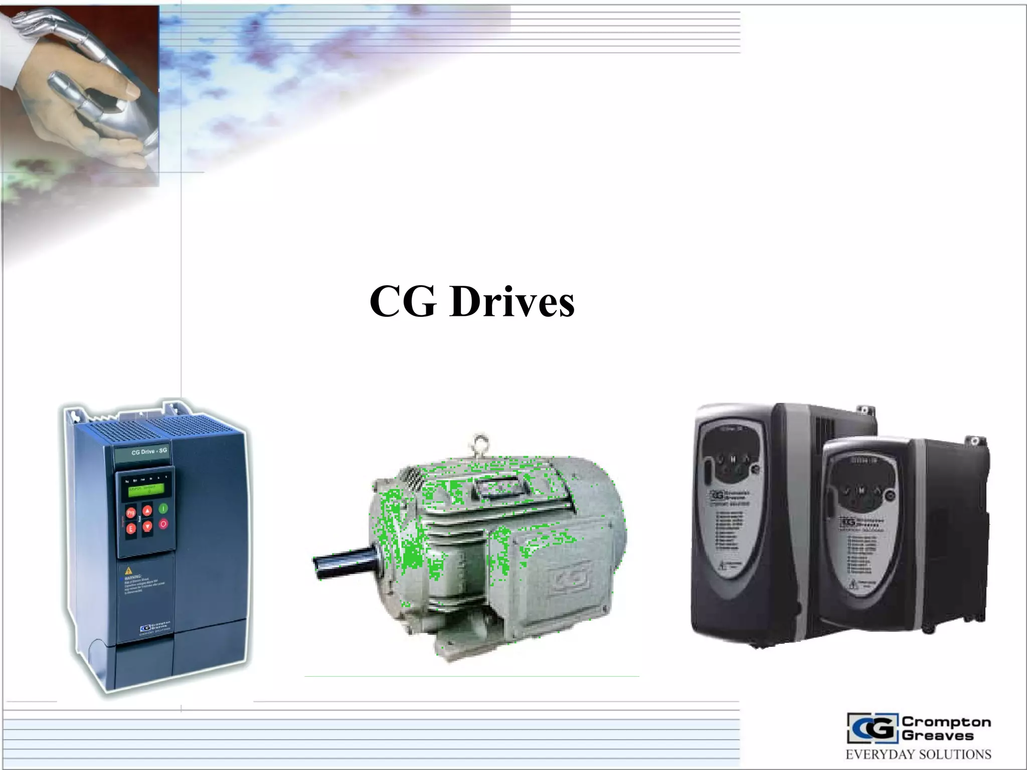
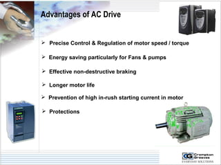
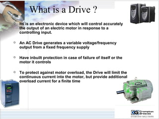
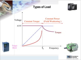
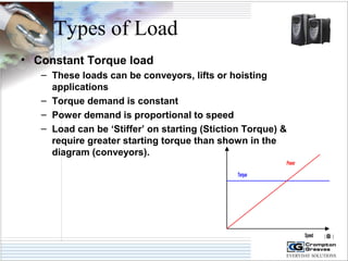
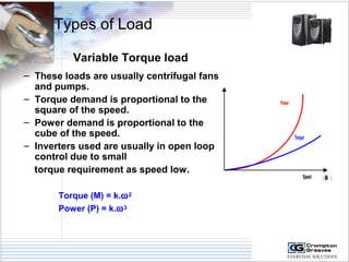
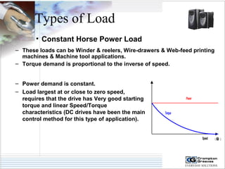
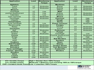
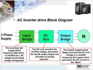
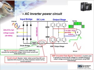
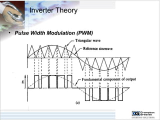
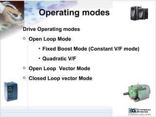
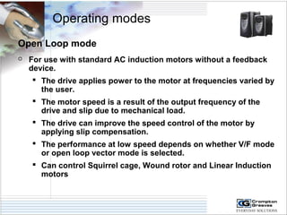
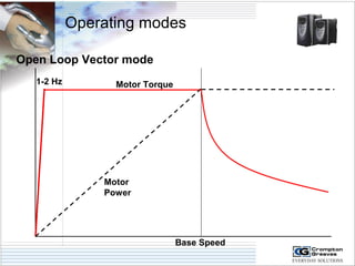
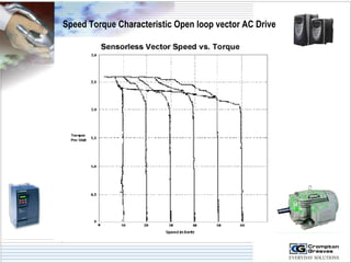
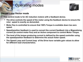
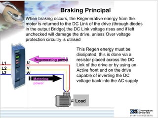
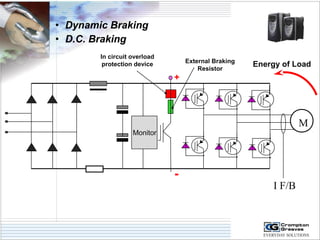
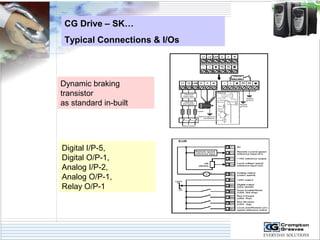
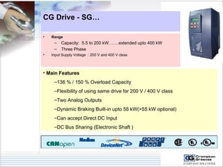
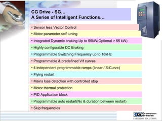
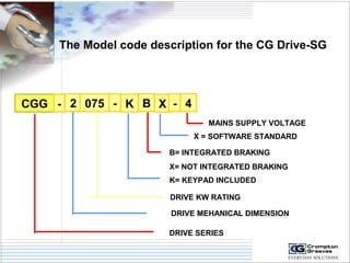
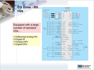
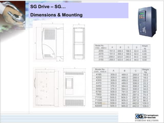
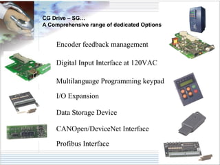
CG Drives
General Theory
Advantages of AC Drive 
 Precise Control & Regulation of motor speed / torque 
 Energy saving particularly for Fans & pumps 
 Effective non-destructive braking 
 Longer motor life 
 Prevention of high in-rush starting current in motor 
 Protections
What is a Drive ? 
 Its is an electronic device which will control accurately 
the output of an electric motor in response to a 
controlling input. 
 An AC Drive generates a variable voltage/frequency 
output from a fixed frequency supply 
 Have inbuilt protection in case of failure of itself or the 
motor it controls 
 To protect against motor overload, the Drive will limit the 
continuous current into the motor, but provide additional 
overload current for a finite time
What is a Drive ? 
 The motor output will be totally variable within the 
performance of the drive and motor. 
 Drives can be called:- 
• Inverters, 
• VSD’s (Variable Speed Drives) 
• VFD’s (Variable Frequency Drives) 
• ASD’s (Adjustable Speed Drives) 
• AFD’s (Adjustable Frequency Drives) 
• Motor controllers 
 Although these products have different names, the 
hardware used is very similar (Input stage / DC Link / 
Output stage), only the Drives internal software 
(fimware) algorithm is different.
AC Drive Working Principle 
N = (120 X f ) / P 
T µ F X I 
F µ V / f 
P = (T X N) / 9550
Basic Principles of 
Modes of operations 
Frequency 
Voltage 
415V 
fb 
Constant Torque 
Constant Power 
(Field Weakening ) 
Torque 
Torque 
Boost
Types of Load
Types of Load 
Frequency 
Voltage 
415V 
fb 
Constant Torque 
Constant Power 
(Field Weakening ) 
Torque 
Torque 
Boost
Types of Load 
• Constant Torque load 
– These loads can be conveyors, lifts or hoisting 
applications 
– Torque demand is constant 
– Power demand is proportional to speed 
– Load can be ‘Stiffer’ on starting (Stiction Torque) & 
require greater starting torque than shown in the 
diagram (conveyors). 
Speed (w ) 
Torque 
Power
Types of Load 
Variable Torque load 
– These loads are usually centrifugal fans 
and pumps. 
– Torque demand is proportional to the 
square of the speed. 
– Power demand is proportional to the 
cube of the speed. 
– Inverters used are usually in open loop 
control due to small 
torque requirement as speed low. 
Torque (M) = k.w2 
Power (P) = k.w3 
Power 
Torque 
Speed ( w )
Types of Load 
• Constant Horse Power Load 
– These loads can be Winder & reelers, Wire-drawers & Web-feed printing 
machines & Machine tool applications. 
– Torque demand is proportional to the inverse of speed. 
– Power demand is constant. 
– Load largest at or close to zero speed, 
requires that the drive has Very good starting 
torque and linear Speed/Torque 
characteristics (DC drives have been the main 
control method for this type of application). 
Torque 
Speed (w ) 
Power
Application Load Breakaway Application Load Breakaway 
Torque Torque 
Agitators Machines 
Liquid VT Moderates Boring CT Moderates 
Slurry VT Moderates Botting CT Moderates 
Blowers Milling CHP Moderates 
Centrifugal VT Low Mills 
positive displacement CT Low Rolling CT Moderates 
Calenders CT Low Rubbers CT Moderates 
Card machines CT Moderates Mixers 
Centrifuges CT Moderates Chemical CT High 
chippers CT Dough CT High 
Compressors Slurry CT High 
Axial centrifugal VT Low Plows- conveyor CT Moderates 
Reciprocating CT Moderates Presses 
Rotary CT Moderates Printing CT Moderates 
Conveyors Punch CT Moderates 
Belt CT Moderates Pullers-car CT Moderates 
SCREW CT High Pumps 
Shaker CT Moderates Centrifugal VT Low 
Cranes Positive displacement CT Moderates 
Bridge CT Moderates Slurry CT High 
Trolly CT Moderates Roll Benders CT Moderates 
Hoist CT Moderates Sanders CT Low 
Crushers CT High Saws CT Moderates 
Drill Presses CHP Moderates Shears CT Low 
Elevators CT Moderates Tension Drives CHP Moderates 
Extruders CT Moderates Tool Machines CHP Moderates 
Fans- centrifugal VT Low Trademills CT Low 
Frames - spinning CHP Low Winders CHP Moderates 
Grinders CHP Moderates 
Kilns CT High 
Looms CT Moderates 
Lathes CHP Moderates 
VT= Varable Torque 
CT= Constat Torque 
CHP= Constant Horse Power 
High = Greater than 150% Torque 
Moderate = Between and including 100% to 150% torque 
Low = Less than 100% Torque
• AC Inverter drive Block Diagram 
3 Phase 
Supply M 
Input 
Bridge 
DC 
Bus 
Output 
Bridge 
The incoming 3ph 
supply (fixed 
frequency 220v/415v) 
is rectified to a DC 
voltage by the diode 
bridge arrangement 
The DC Link smooths the 
rectified voltage, decouples 
the input& output stages and 
provides an energy 
reservoir. 
The Output stage(inverter 
Stage) converts the DC Link 
voltage to a variable 
frequency AC supply which 
generates the AC current in 
the Motor
» AC Inverter power circuit 
M 
3ph Input supply Output Voltage 
U 
V 
W 
Motor current 
220v/415v 3ph 
voltage supply 
(50~60Hz) 
Input Bridge DC Link Output Stage 
Diode Bridge DC Link IGBT Output Stage 
The DC Link Inductance (used on units >4kW only) 
smooths the rectified DC voltage, limits inrush current and 
limits fault current 
Inrush circuit. Resistor limits initial current flow (DC Link 
capacitors S/C at power-up), Relay bypasses resistor during 
normal operation. 
IGBT (Insulated Gate Bipolar Transistor). A switch used 
in groups to convert the DC voltage to a variable frequency 
output voltage (controlled via microprocessor using PWM 
methodology) 
600~800vDC 
0~220 / 415v 
variable F 
output
Inverter Theory 
• Pulse Width Modulation (PWM)
AC Drive 
Operating modes
Operating modes 
Drive Operating modes 
 Open Loop Mode 
• Fixed Boost Mode (Constant V/F mode) 
• Quadratic V/F 
 Open Loop Vector Mode 
 Closed Loop vector Mode
V/F Mode
Operating modes 
Open Loop mode 
 For use with standard AC induction motors without a feedback 
device. 
 The drive applies power to the motor at frequencies varied by 
the user. 
 The motor speed is a result of the output frequency of the 
drive and slip due to mechanical load. 
 The drive can improve the speed control of the motor by 
applying slip compensation. 
 The performance at low speed depends on whether V/F mode 
or open loop vector mode is selected. 
 Can control Squirrel cage, Wound rotor and Linear Induction 
motors
Operating modes 
Open Loop - Constant V/F 
 A versatile control mode for single or multi -motor control 
 The voltage applied to the machine is proportional to the frequency 
 At low frequencies a fixed boost is added to compensate for the voltage drop due to 
the machines resistance (Boost voltage 0 ~25% of maximum motor voltage). 
 The drive output frequency is defined by the selected frequency reference (up to a 
maximum of 1500Hz). 
 The drive includes slip compensation so that speed can be held constant with 
varying load 
 Can be used with other types of motors or variable frequency supply applications 
 If the machine load current exceeds the drive limit, the frequency is modified to 
reduce the load.
Operating modes 
Open Loop - Constant V/F 
100% Rated F 
2 
Output voltage 
100% Motor 
Rated Voltage 
Motor Rated Voltage 
2 
Boost Voltage (%) 
Output frequency 
100% Motor Rated F
Operating modes 
Open Loop – Quadratic V/F 
 A control mode for single motors operating fans or pumps with 
Quadratic load characteristics 
 The voltage applied to the motor is directly proportional to the 
square of the frequency applied to the motor. 
 At low frequencies a fixed boost is added to compensate for the voltage 
drop due to the machines resistance (Boost voltage 0 ~25% of maximum 
motor voltage). 
 The drive output frequency is defined by the selected frequency reference 
(up to a maximum of 1500Hz). 
 The drive includes slip compensation so that speed can be held constant 
with varying load 
 This operating mode is not suitable if a high starting torque is required.
Operating modes 
Open Loop – Quadratic V/F 
100% Motor 
Rated Voltage (V) 
Boost Voltage (%) 
Output frequency 
100% Motor Rated F (Hz)
Speed Torque characteristic V F AC Drive
Open Loop Vector mode
Operating modes 
Open Loop Vector mode 
 This is the default operating mode in Open loop 
 The voltage applied to the machine is proportional to the frequency 
 At low frequencies (below half motor rated frequency), stator resistance compensation is 
applied to give optimum starting torque, the information for this is provided via an auto-tune of 
the motor characteristics. 
 An auto-tune function can be carried via the drive to calculate the stator resistance and 
voltage offset value for the motor equivalent circuit. 
 An Autotune can also be carried out to accurately calculate the motor power factor. 
 Typically, 100% load Torque is available down 1Hz from a 50Hz motor. 
 Differing modes of operation compensate for resistance changes due to temperature changes.
Operating modes 
Open Loop Vector mode 
 This is the default operating mode in Open loop 
 The Information provided is used to control the motor flux to 
provide optimum Torque. 
 Slip compensation can also be applied via parameter settings in the 
Drive.
Operating modes 
Open Loop Vector mode 
Motor 
Power 
Base Speed 
1-2 Hz Motor Torque
Speed Torque Characteristic Open loop vector AC Drive
Closed Loop Vector mode
Operating modes 
Closed Loop Vector mode 
 This control mode is for AC induction motors with a feedback device. 
 The drive controls the speed of the motor using the feedback device to ensure the 
rotor speed is exactly as demanded. 
 Motor flux is controlled to ensure that 100% Torque is available down too zero 
speed. 
 Speed/position feedback is used to convert the current feedback into a Magnetising 
current (to control motor flux) and an Active component to control Motor Torque. 
 The level of the torque producing current is defined by the speed controller using 
the speed/position feedback to determine the actual motor speed. 
 The Speed Loop and Current loop of the Drive have variable gain values to allow 
for different load characteristics.
Operating modes 
Closed Loop Vector mode 
 This control mode is for AC induction motors with a feedback device. 
 Inertia measurement of the Combined motor/load inertia can be 
carried out to aid setting of speed loop PID gains. 
 Current Loop gain values are calculated when an autotune function 
is carried out .
Operating modes 
100% 
Closed Loop Vector mode 
Motor 
Power 
Motor Speed 
Base Speed 
Motor Torque
Operating modes 
Closed Loop Vector mode 
I Loop 
gains 
Speed error 
Speed 
Loop gains 
IFb 
Position Fb 
Speed Loop Output / 
Current reference 
Current error 
Speed reference 
E
AC Drives Braking
Types of Braking 
- Dynamic Braking 
- D.C. Injection Braking 
- Regenerative Braking
Braking Principal 
When braking occurs, the Regenerative energy from the 
motor is returned to the DC Link of the drive (through diodes 
in the output Bridge),the DC Link voltage rises and if left 
unchecked will damage the drive, unless Over voltage 
protection circuitry is utilised 
Regenerating power 
Motoring 
power 
U 
Load 
L1 
L2 
L3 
VW 
This Regen energy must be 
dissipated, this is done via a 
resistor placed across the DC 
Link of the drive or by using an 
Active front end on the drive 
capable of inverting the DC 
voltage back into the AC supply
• Dynamic Braking 
• D.C. Braking 
Monitor 
+ 
- 
M 
I F/B 
In circuit overload 
protection device External Braking 
Resistor Energy of Load
CG Drives
Crompton Greaves… 
CG Drives 
Benefits of Choosing AC Drives from CG….. 
• Single Point Reference for both ,Motor & AC Drive 
• Package Performance guaranteed by CG. 
• Perfect Selection of Motor and Drives ,together. 
• CG’s Technical team extensively tests CG Motors and CG Drives,together. 
• CG Understands applications and package solution can be tailored 
according to the need of your application. 
Just tell us your application…… 
.…..And CG offers you Packaged solution ! 
………..And Standalone Drives too!
CG Drive-SK
Over View of CG Drive-SK
CG Drive - SK… 
• Range 
– Single Phase : 0.25 kW upto 0.75 kW 
– Dual Phase : 1.1 kW upto 2.2 kW 
– Three Phase : 0.37 kW upto 45 kW 
• Input Voltage Supply : 200V and 400V class 
• Main Features 
– Sensorless Vector Drive 
– Very Compact,Simple to use and Flexible range 
– Dynamic Braking Built-in for entire range 
– PLC functionality built-in with lot of Input/Outputs 
– Built-in EMC Filter 
– Communication Port (RS 485) as standard 
Approvals - UL, CUL, CE, ISO14001, ISO9001:2000
The Model code description for the CG Drive-SK 
CGK 4 3 XXXXX 
Drive kilowatt rating: 00025 = 0.25kW 
Number of input phases: 1 = 1phase, 
3 = 3phase, D = 1 and 3phase 
Drive voltage rating: 2 = 230V, 4 = 
400V 
Model: CG DRIVE-SK
Model Number wise ratings for entire range
CG Drive – SK… 
Dimensions (Upto 4kW) 
0.95-1.0kG 1.2-1.4kG 2.1kG
CG Drive – SK… 
Dimensions (7.5kW to 45kW) 
7 kG 15 kG 
30 kG
CG Drive – SK… 
Typical Connections & I/Os 
Dynamic braking 
transistor 
as standard in-built 
Digital I/P-5, 
Digital O/P-1, 
Analog I/P-2, 
Analog O/P-1, 
Relay O/P-1
CG Drive - SG
CG Drive - SG… 
• Range 
– Capacity: 5.5 to 200 kW…….extended upto 400 kW 
– Three Phase 
• Input Supply Voltage : 200 V and 400 V class 
• Main Features 
–136 % / 150 % Overload Capacity 
–Flexibility of using same drive for 200 V / 400 V class 
–Two Analog Outputs 
–Dynamic Braking Built-in upto 55 kW(>55 kW optional) 
–Can accept Direct DC Input 
–DC Bus Sharing (Electronic Shaft )
CG Drive - SG… 
A Series of Intelligent Functions… 
• Sensor less Vector Control 
• Motor parameter self tuning 
• Integrated Dynamic braking Up to 55kW(Optional > 55 kW) 
• Highly configurable DC Braking 
• Programmable Switching Frequency up to 16kHz 
• Programmable & predefined V/f curves 
• 4 independent programmable ramps (linear / S-Curve) 
• Flying restart 
• Mains loss detection with controlled stop 
• Motor thermal protection 
• PID Application block 
• Programmable auto restart(No & duration between restart) 
• Skip frequencies
The Model code description for the CG Drive-SG 
CGG - 
2 075 - K B X - 4 
MAINS SUPPLY VOLTAGE 
X = SOFTWARE STANDARD 
B= INTEGRATED BRAKING 
X= NOT INTEGRATED BRAKING 
K= KEYPAD INCLUDED 
DRIVE KW RATING 
DRIVE MEHANICAL DIMENSION 
DRIVE SERIES
CG Drive - SG… 
I/Os 
Equipped with a large 
number of standard 
I/Os… 
• 3 Differential Analog I/Ps 
• 8 Digital I/P 
• 2 Analog O/Ps 
• 4 Digital O/Ps
SG Drive – SG… 
Dimensions & Mounting
CG Drive – SG… 
A Comprehensive range of dedicated Options 
Encoder feedback management 
Digital Input Interface at 120VAC 
Multilanguage Programming keypad 
I/O Expansion 
Data Storage Device 
CANOpen/DeviceNet Interface 
Profibus Interface
Selection of Inverter
Motor rated current 
MACHINE NO. NADWN 30425 BT TOP FRAME NDW225S 
KW(HP) 20(27) RPM 970 EFF(FL) 86 % 
VOLT 415 A 37 DUTY S4 (60%) 
IP 55 CONN. DIAG. 3MS HZ 50 
REF FEAM3296 INS . CL. F AMB 45 C 
GREASE MADE IN 
INDIA 
LITHIUM BASE 2 3 PHASE INDUCTION MOTOR REF . IS 329 
Motor rated Voltage 
(Pr08) 
Rated full-load speed (Rpm) 
(Pr07) 
kW Output power 
(Pr06) 
Getting Started
Inputs to be taken from User… 
while selecting the Inverter 
 Types of load driven 
 Load Requirements 
1. Constant Torque 
2. Variable Torque 
3. Constant power 
 Existing motor Name plate details 
 Load speed Requirements . 
 One,Two or Four Quadrants. 
 Accuracy and response time. 
 Control with speed sensor or sensorless control. 
 Environmental consideration(Ambient temp,Humidity,Altitude) 
 System interfacing requirement
Major Customers 
Fans & Pumps 
Applications
SL. No. Customer Rating QTY. Application Y.O.S 
1 Durgapur Steel 160KW 3 Gas Booster Fan 2006 
2 Veda Engg. 
Pvt. Ltd. - Pune 
75KW 6 CT Fan 2006 
3 GMDC-Ahmedabad 
200KW 1 ID Fan 2006 
4 BILT-Chandrapur 
250KW 2 Feed Pump 2007 
5 BILT-Chandrapur 
160KW 3 ID Fan 2007 
6 BILT-Jaypure, 
Orissa 
90KW 2 Pump 2007 
7 IFFCO-Paradip 
Orissa 
75KW,45K 
W,37KW 
2 each Pump 2007 
6 BILT-Yamunanagar 
250KW 1 ID Fan 2007 
7 Trivista Steel & 
Power Ltd.- 
Karnataka 
200KW 1 ID Fan 2008
Energy Saving CG Drives
SL. No. Application VFD 
Rating 
KW W/O 
VFD 
KW 
With 
VFD 
KW 
Saving 
1 Fan 160KW 124KW 116KW 8KW 
2 Blow Tank 
Pumps 
75KW 50KW 25KW 25KW 
3 Pump 37KW 29KW 22KW 7KW 
4 ID Fan 110KW 74KW 36KW 38KW 
5 White Liquid 
Supply Pumps 
18.5KW 14KW 10.5KW 3.5KW 
6 Ash Mixing 
Pumps 
37KW 32KW 20KW 12KW 
Data provided by M/s BILT-Chandrapur
SL. 
No. 
Customer Rating QTY. Applicatio 
n 
Y.O.S 
8 Wacker Metroarc 
Chemicals Pvt. Ltd. 
2.2KW to 
90KW 
>15 Pump 2006-09 
9 Ruchira Paper Mills 
Ltd.-Baddi(HP) 
132KW, 
45KW,37KW 
1 
each 
ID/PA/SA 
Fans 
2008 
10 Anvil Cables Ltd.- 
Jamshedpur 
110KW,45KW 1 Wire Drawing 2006 
11 DSPL-Jajpur(Orissa) 75KW 2 DRI Kiln, 
SAF 
2009 
12 Jindal India Ltd. 75KW 1 Fan 2009 
14 Rupa & Company 
Ltd.-Kolkata 
45KW,37KW & 
1.5KW 
2 
each 
Boiler 
Applications 
2008 
13 Presales Pvt. Ltd. 
(OEM Boiler)- 
Cuttack(Orissa) 
0.75KW to 
200KW 
>30 Boiler 
applications 
2006-09

Drives training

  • 1.
  • 2.
  • 3.
    Advantages of ACDrive  Precise Control & Regulation of motor speed / torque  Energy saving particularly for Fans & pumps  Effective non-destructive braking  Longer motor life  Prevention of high in-rush starting current in motor  Protections
  • 4.
    What is aDrive ?  Its is an electronic device which will control accurately the output of an electric motor in response to a controlling input.  An AC Drive generates a variable voltage/frequency output from a fixed frequency supply  Have inbuilt protection in case of failure of itself or the motor it controls  To protect against motor overload, the Drive will limit the continuous current into the motor, but provide additional overload current for a finite time
  • 5.
    What is aDrive ?  The motor output will be totally variable within the performance of the drive and motor.  Drives can be called:- • Inverters, • VSD’s (Variable Speed Drives) • VFD’s (Variable Frequency Drives) • ASD’s (Adjustable Speed Drives) • AFD’s (Adjustable Frequency Drives) • Motor controllers  Although these products have different names, the hardware used is very similar (Input stage / DC Link / Output stage), only the Drives internal software (fimware) algorithm is different.
  • 6.
    AC Drive WorkingPrinciple N = (120 X f ) / P T µ F X I F µ V / f P = (T X N) / 9550
  • 7.
    Basic Principles of Modes of operations Frequency Voltage 415V fb Constant Torque Constant Power (Field Weakening ) Torque Torque Boost
  • 8.
  • 9.
    Types of Load Frequency Voltage 415V fb Constant Torque Constant Power (Field Weakening ) Torque Torque Boost
  • 10.
    Types of Load • Constant Torque load – These loads can be conveyors, lifts or hoisting applications – Torque demand is constant – Power demand is proportional to speed – Load can be ‘Stiffer’ on starting (Stiction Torque) & require greater starting torque than shown in the diagram (conveyors). Speed (w ) Torque Power
  • 11.
    Types of Load Variable Torque load – These loads are usually centrifugal fans and pumps. – Torque demand is proportional to the square of the speed. – Power demand is proportional to the cube of the speed. – Inverters used are usually in open loop control due to small torque requirement as speed low. Torque (M) = k.w2 Power (P) = k.w3 Power Torque Speed ( w )
  • 12.
    Types of Load • Constant Horse Power Load – These loads can be Winder & reelers, Wire-drawers & Web-feed printing machines & Machine tool applications. – Torque demand is proportional to the inverse of speed. – Power demand is constant. – Load largest at or close to zero speed, requires that the drive has Very good starting torque and linear Speed/Torque characteristics (DC drives have been the main control method for this type of application). Torque Speed (w ) Power
  • 13.
    Application Load BreakawayApplication Load Breakaway Torque Torque Agitators Machines Liquid VT Moderates Boring CT Moderates Slurry VT Moderates Botting CT Moderates Blowers Milling CHP Moderates Centrifugal VT Low Mills positive displacement CT Low Rolling CT Moderates Calenders CT Low Rubbers CT Moderates Card machines CT Moderates Mixers Centrifuges CT Moderates Chemical CT High chippers CT Dough CT High Compressors Slurry CT High Axial centrifugal VT Low Plows- conveyor CT Moderates Reciprocating CT Moderates Presses Rotary CT Moderates Printing CT Moderates Conveyors Punch CT Moderates Belt CT Moderates Pullers-car CT Moderates SCREW CT High Pumps Shaker CT Moderates Centrifugal VT Low Cranes Positive displacement CT Moderates Bridge CT Moderates Slurry CT High Trolly CT Moderates Roll Benders CT Moderates Hoist CT Moderates Sanders CT Low Crushers CT High Saws CT Moderates Drill Presses CHP Moderates Shears CT Low Elevators CT Moderates Tension Drives CHP Moderates Extruders CT Moderates Tool Machines CHP Moderates Fans- centrifugal VT Low Trademills CT Low Frames - spinning CHP Low Winders CHP Moderates Grinders CHP Moderates Kilns CT High Looms CT Moderates Lathes CHP Moderates VT= Varable Torque CT= Constat Torque CHP= Constant Horse Power High = Greater than 150% Torque Moderate = Between and including 100% to 150% torque Low = Less than 100% Torque
  • 14.
    • AC Inverterdrive Block Diagram 3 Phase Supply M Input Bridge DC Bus Output Bridge The incoming 3ph supply (fixed frequency 220v/415v) is rectified to a DC voltage by the diode bridge arrangement The DC Link smooths the rectified voltage, decouples the input& output stages and provides an energy reservoir. The Output stage(inverter Stage) converts the DC Link voltage to a variable frequency AC supply which generates the AC current in the Motor
  • 15.
    » AC Inverterpower circuit M 3ph Input supply Output Voltage U V W Motor current 220v/415v 3ph voltage supply (50~60Hz) Input Bridge DC Link Output Stage Diode Bridge DC Link IGBT Output Stage The DC Link Inductance (used on units >4kW only) smooths the rectified DC voltage, limits inrush current and limits fault current Inrush circuit. Resistor limits initial current flow (DC Link capacitors S/C at power-up), Relay bypasses resistor during normal operation. IGBT (Insulated Gate Bipolar Transistor). A switch used in groups to convert the DC voltage to a variable frequency output voltage (controlled via microprocessor using PWM methodology) 600~800vDC 0~220 / 415v variable F output
  • 16.
    Inverter Theory •Pulse Width Modulation (PWM)
  • 17.
  • 18.
    Operating modes DriveOperating modes  Open Loop Mode • Fixed Boost Mode (Constant V/F mode) • Quadratic V/F  Open Loop Vector Mode  Closed Loop vector Mode
  • 19.
  • 20.
    Operating modes OpenLoop mode  For use with standard AC induction motors without a feedback device.  The drive applies power to the motor at frequencies varied by the user.  The motor speed is a result of the output frequency of the drive and slip due to mechanical load.  The drive can improve the speed control of the motor by applying slip compensation.  The performance at low speed depends on whether V/F mode or open loop vector mode is selected.  Can control Squirrel cage, Wound rotor and Linear Induction motors
  • 21.
    Operating modes OpenLoop - Constant V/F  A versatile control mode for single or multi -motor control  The voltage applied to the machine is proportional to the frequency  At low frequencies a fixed boost is added to compensate for the voltage drop due to the machines resistance (Boost voltage 0 ~25% of maximum motor voltage).  The drive output frequency is defined by the selected frequency reference (up to a maximum of 1500Hz).  The drive includes slip compensation so that speed can be held constant with varying load  Can be used with other types of motors or variable frequency supply applications  If the machine load current exceeds the drive limit, the frequency is modified to reduce the load.
  • 22.
    Operating modes OpenLoop - Constant V/F 100% Rated F 2 Output voltage 100% Motor Rated Voltage Motor Rated Voltage 2 Boost Voltage (%) Output frequency 100% Motor Rated F
  • 23.
    Operating modes OpenLoop – Quadratic V/F  A control mode for single motors operating fans or pumps with Quadratic load characteristics  The voltage applied to the motor is directly proportional to the square of the frequency applied to the motor.  At low frequencies a fixed boost is added to compensate for the voltage drop due to the machines resistance (Boost voltage 0 ~25% of maximum motor voltage).  The drive output frequency is defined by the selected frequency reference (up to a maximum of 1500Hz).  The drive includes slip compensation so that speed can be held constant with varying load  This operating mode is not suitable if a high starting torque is required.
  • 24.
    Operating modes OpenLoop – Quadratic V/F 100% Motor Rated Voltage (V) Boost Voltage (%) Output frequency 100% Motor Rated F (Hz)
  • 25.
  • 26.
  • 27.
    Operating modes OpenLoop Vector mode  This is the default operating mode in Open loop  The voltage applied to the machine is proportional to the frequency  At low frequencies (below half motor rated frequency), stator resistance compensation is applied to give optimum starting torque, the information for this is provided via an auto-tune of the motor characteristics.  An auto-tune function can be carried via the drive to calculate the stator resistance and voltage offset value for the motor equivalent circuit.  An Autotune can also be carried out to accurately calculate the motor power factor.  Typically, 100% load Torque is available down 1Hz from a 50Hz motor.  Differing modes of operation compensate for resistance changes due to temperature changes.
  • 28.
    Operating modes OpenLoop Vector mode  This is the default operating mode in Open loop  The Information provided is used to control the motor flux to provide optimum Torque.  Slip compensation can also be applied via parameter settings in the Drive.
  • 29.
    Operating modes OpenLoop Vector mode Motor Power Base Speed 1-2 Hz Motor Torque
  • 30.
    Speed Torque CharacteristicOpen loop vector AC Drive
  • 31.
  • 32.
    Operating modes ClosedLoop Vector mode  This control mode is for AC induction motors with a feedback device.  The drive controls the speed of the motor using the feedback device to ensure the rotor speed is exactly as demanded.  Motor flux is controlled to ensure that 100% Torque is available down too zero speed.  Speed/position feedback is used to convert the current feedback into a Magnetising current (to control motor flux) and an Active component to control Motor Torque.  The level of the torque producing current is defined by the speed controller using the speed/position feedback to determine the actual motor speed.  The Speed Loop and Current loop of the Drive have variable gain values to allow for different load characteristics.
  • 33.
    Operating modes ClosedLoop Vector mode  This control mode is for AC induction motors with a feedback device.  Inertia measurement of the Combined motor/load inertia can be carried out to aid setting of speed loop PID gains.  Current Loop gain values are calculated when an autotune function is carried out .
  • 34.
    Operating modes 100% Closed Loop Vector mode Motor Power Motor Speed Base Speed Motor Torque
  • 35.
    Operating modes ClosedLoop Vector mode I Loop gains Speed error Speed Loop gains IFb Position Fb Speed Loop Output / Current reference Current error Speed reference E
  • 36.
  • 37.
    Types of Braking - Dynamic Braking - D.C. Injection Braking - Regenerative Braking
  • 38.
    Braking Principal Whenbraking occurs, the Regenerative energy from the motor is returned to the DC Link of the drive (through diodes in the output Bridge),the DC Link voltage rises and if left unchecked will damage the drive, unless Over voltage protection circuitry is utilised Regenerating power Motoring power U Load L1 L2 L3 VW This Regen energy must be dissipated, this is done via a resistor placed across the DC Link of the drive or by using an Active front end on the drive capable of inverting the DC voltage back into the AC supply
  • 39.
    • Dynamic Braking • D.C. Braking Monitor + - M I F/B In circuit overload protection device External Braking Resistor Energy of Load
  • 40.
  • 41.
    Crompton Greaves… CGDrives Benefits of Choosing AC Drives from CG….. • Single Point Reference for both ,Motor & AC Drive • Package Performance guaranteed by CG. • Perfect Selection of Motor and Drives ,together. • CG’s Technical team extensively tests CG Motors and CG Drives,together. • CG Understands applications and package solution can be tailored according to the need of your application. Just tell us your application…… .…..And CG offers you Packaged solution ! ………..And Standalone Drives too!
  • 42.
  • 43.
    Over View ofCG Drive-SK
  • 44.
    CG Drive -SK… • Range – Single Phase : 0.25 kW upto 0.75 kW – Dual Phase : 1.1 kW upto 2.2 kW – Three Phase : 0.37 kW upto 45 kW • Input Voltage Supply : 200V and 400V class • Main Features – Sensorless Vector Drive – Very Compact,Simple to use and Flexible range – Dynamic Braking Built-in for entire range – PLC functionality built-in with lot of Input/Outputs – Built-in EMC Filter – Communication Port (RS 485) as standard Approvals - UL, CUL, CE, ISO14001, ISO9001:2000
  • 45.
    The Model codedescription for the CG Drive-SK CGK 4 3 XXXXX Drive kilowatt rating: 00025 = 0.25kW Number of input phases: 1 = 1phase, 3 = 3phase, D = 1 and 3phase Drive voltage rating: 2 = 230V, 4 = 400V Model: CG DRIVE-SK
  • 46.
    Model Number wiseratings for entire range
  • 47.
    CG Drive –SK… Dimensions (Upto 4kW) 0.95-1.0kG 1.2-1.4kG 2.1kG
  • 48.
    CG Drive –SK… Dimensions (7.5kW to 45kW) 7 kG 15 kG 30 kG
  • 49.
    CG Drive –SK… Typical Connections & I/Os Dynamic braking transistor as standard in-built Digital I/P-5, Digital O/P-1, Analog I/P-2, Analog O/P-1, Relay O/P-1
  • 50.
  • 51.
    CG Drive -SG… • Range – Capacity: 5.5 to 200 kW…….extended upto 400 kW – Three Phase • Input Supply Voltage : 200 V and 400 V class • Main Features –136 % / 150 % Overload Capacity –Flexibility of using same drive for 200 V / 400 V class –Two Analog Outputs –Dynamic Braking Built-in upto 55 kW(>55 kW optional) –Can accept Direct DC Input –DC Bus Sharing (Electronic Shaft )
  • 52.
    CG Drive -SG… A Series of Intelligent Functions… • Sensor less Vector Control • Motor parameter self tuning • Integrated Dynamic braking Up to 55kW(Optional > 55 kW) • Highly configurable DC Braking • Programmable Switching Frequency up to 16kHz • Programmable & predefined V/f curves • 4 independent programmable ramps (linear / S-Curve) • Flying restart • Mains loss detection with controlled stop • Motor thermal protection • PID Application block • Programmable auto restart(No & duration between restart) • Skip frequencies
  • 53.
    The Model codedescription for the CG Drive-SG CGG - 2 075 - K B X - 4 MAINS SUPPLY VOLTAGE X = SOFTWARE STANDARD B= INTEGRATED BRAKING X= NOT INTEGRATED BRAKING K= KEYPAD INCLUDED DRIVE KW RATING DRIVE MEHANICAL DIMENSION DRIVE SERIES
  • 54.
    CG Drive -SG… I/Os Equipped with a large number of standard I/Os… • 3 Differential Analog I/Ps • 8 Digital I/P • 2 Analog O/Ps • 4 Digital O/Ps
  • 55.
    SG Drive –SG… Dimensions & Mounting
  • 56.
    CG Drive –SG… A Comprehensive range of dedicated Options Encoder feedback management Digital Input Interface at 120VAC Multilanguage Programming keypad I/O Expansion Data Storage Device CANOpen/DeviceNet Interface Profibus Interface
  • 57.
  • 58.
    Motor rated current MACHINE NO. NADWN 30425 BT TOP FRAME NDW225S KW(HP) 20(27) RPM 970 EFF(FL) 86 % VOLT 415 A 37 DUTY S4 (60%) IP 55 CONN. DIAG. 3MS HZ 50 REF FEAM3296 INS . CL. F AMB 45 C GREASE MADE IN INDIA LITHIUM BASE 2 3 PHASE INDUCTION MOTOR REF . IS 329 Motor rated Voltage (Pr08) Rated full-load speed (Rpm) (Pr07) kW Output power (Pr06) Getting Started
  • 59.
    Inputs to betaken from User… while selecting the Inverter  Types of load driven  Load Requirements 1. Constant Torque 2. Variable Torque 3. Constant power  Existing motor Name plate details  Load speed Requirements .  One,Two or Four Quadrants.  Accuracy and response time.  Control with speed sensor or sensorless control.  Environmental consideration(Ambient temp,Humidity,Altitude)  System interfacing requirement
  • 60.
    Major Customers Fans& Pumps Applications
  • 61.
    SL. No. CustomerRating QTY. Application Y.O.S 1 Durgapur Steel 160KW 3 Gas Booster Fan 2006 2 Veda Engg. Pvt. Ltd. - Pune 75KW 6 CT Fan 2006 3 GMDC-Ahmedabad 200KW 1 ID Fan 2006 4 BILT-Chandrapur 250KW 2 Feed Pump 2007 5 BILT-Chandrapur 160KW 3 ID Fan 2007 6 BILT-Jaypure, Orissa 90KW 2 Pump 2007 7 IFFCO-Paradip Orissa 75KW,45K W,37KW 2 each Pump 2007 6 BILT-Yamunanagar 250KW 1 ID Fan 2007 7 Trivista Steel & Power Ltd.- Karnataka 200KW 1 ID Fan 2008
  • 62.
  • 63.
    SL. No. ApplicationVFD Rating KW W/O VFD KW With VFD KW Saving 1 Fan 160KW 124KW 116KW 8KW 2 Blow Tank Pumps 75KW 50KW 25KW 25KW 3 Pump 37KW 29KW 22KW 7KW 4 ID Fan 110KW 74KW 36KW 38KW 5 White Liquid Supply Pumps 18.5KW 14KW 10.5KW 3.5KW 6 Ash Mixing Pumps 37KW 32KW 20KW 12KW Data provided by M/s BILT-Chandrapur
  • 64.
    SL. No. CustomerRating QTY. Applicatio n Y.O.S 8 Wacker Metroarc Chemicals Pvt. Ltd. 2.2KW to 90KW >15 Pump 2006-09 9 Ruchira Paper Mills Ltd.-Baddi(HP) 132KW, 45KW,37KW 1 each ID/PA/SA Fans 2008 10 Anvil Cables Ltd.- Jamshedpur 110KW,45KW 1 Wire Drawing 2006 11 DSPL-Jajpur(Orissa) 75KW 2 DRI Kiln, SAF 2009 12 Jindal India Ltd. 75KW 1 Fan 2009 14 Rupa & Company Ltd.-Kolkata 45KW,37KW & 1.5KW 2 each Boiler Applications 2008 13 Presales Pvt. Ltd. (OEM Boiler)- Cuttack(Orissa) 0.75KW to 200KW >30 Boiler applications 2006-09