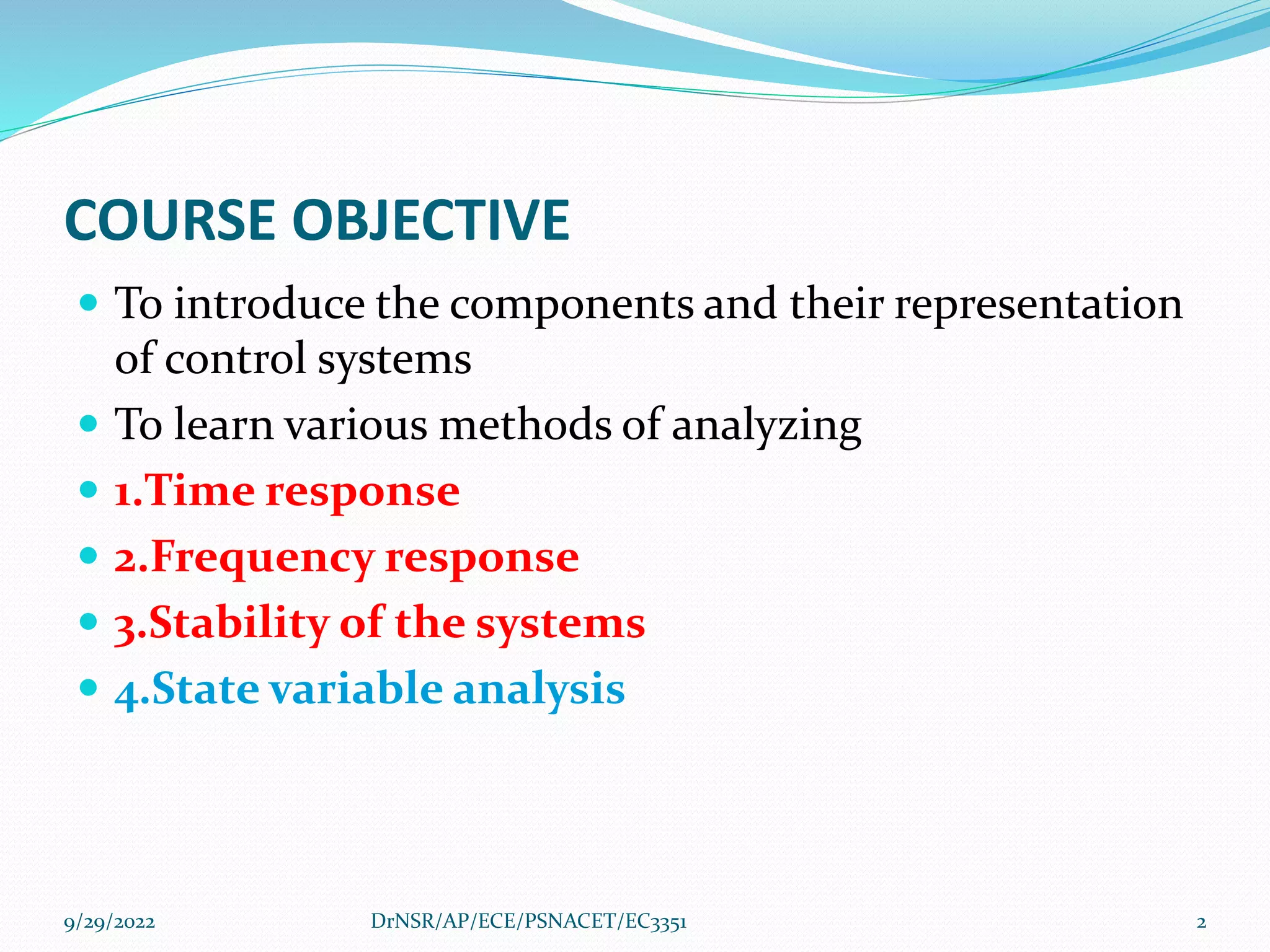
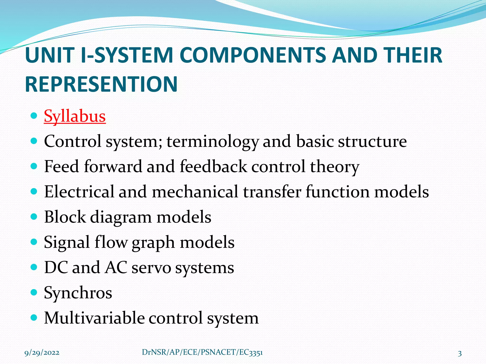
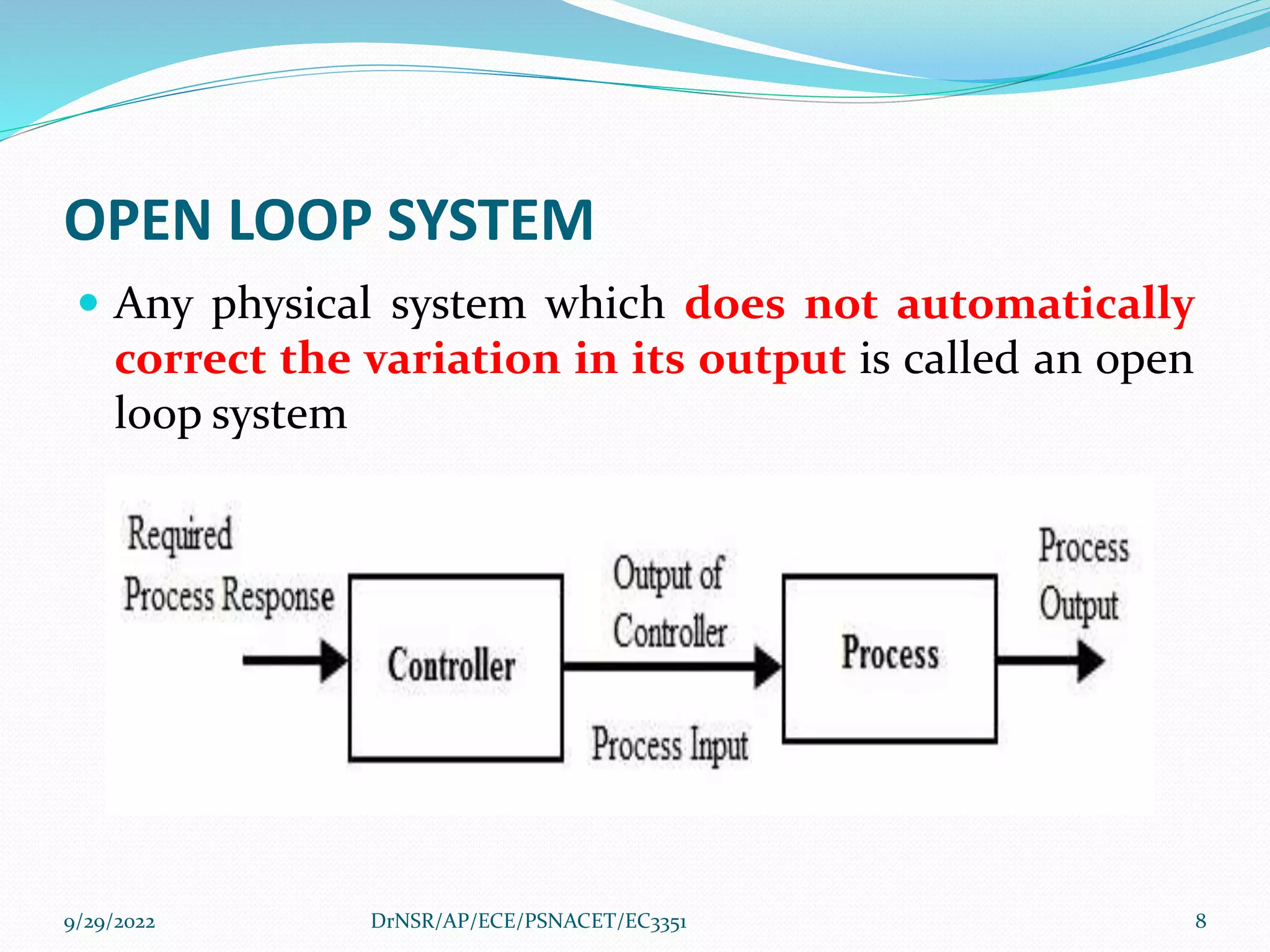
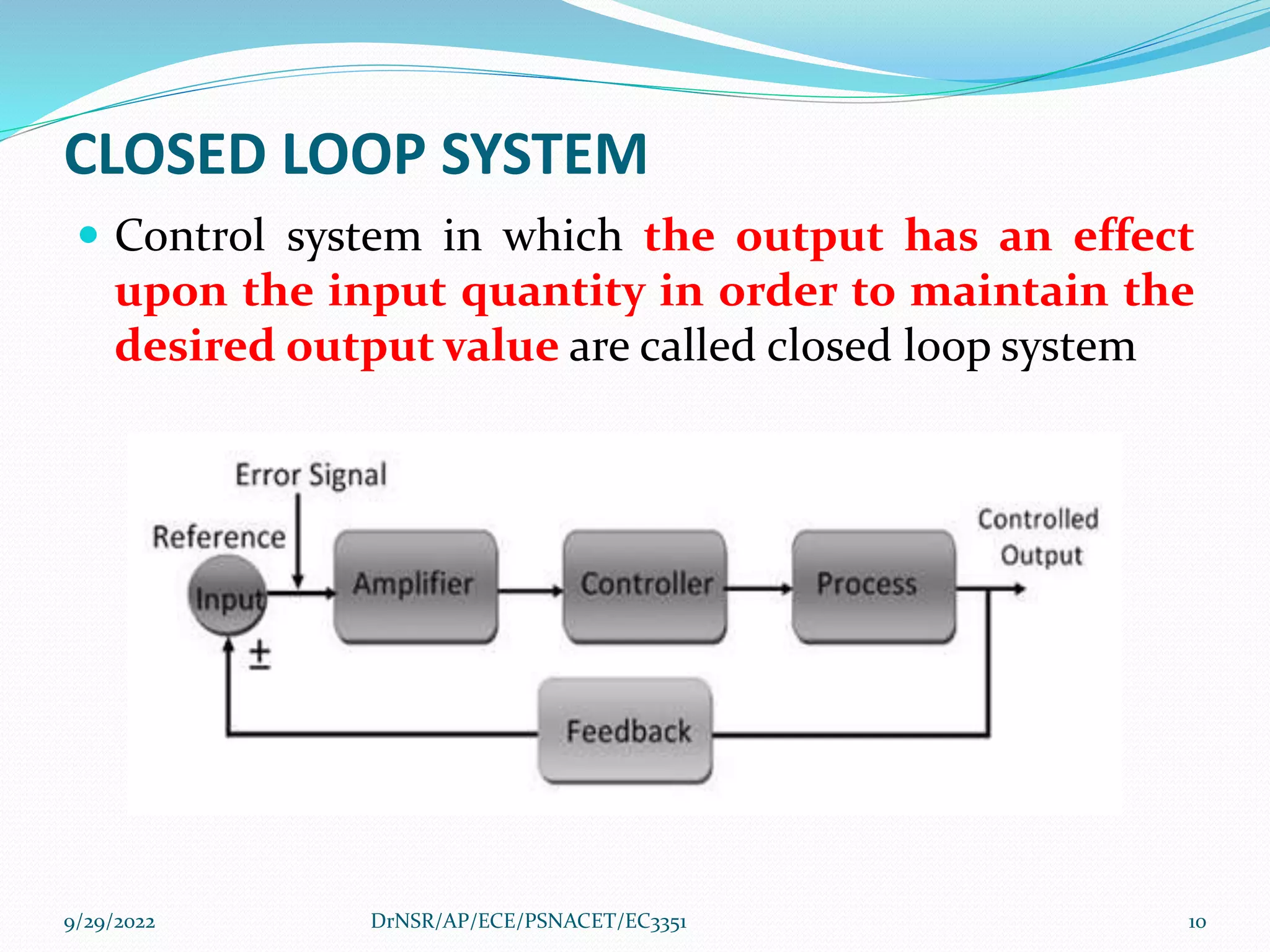
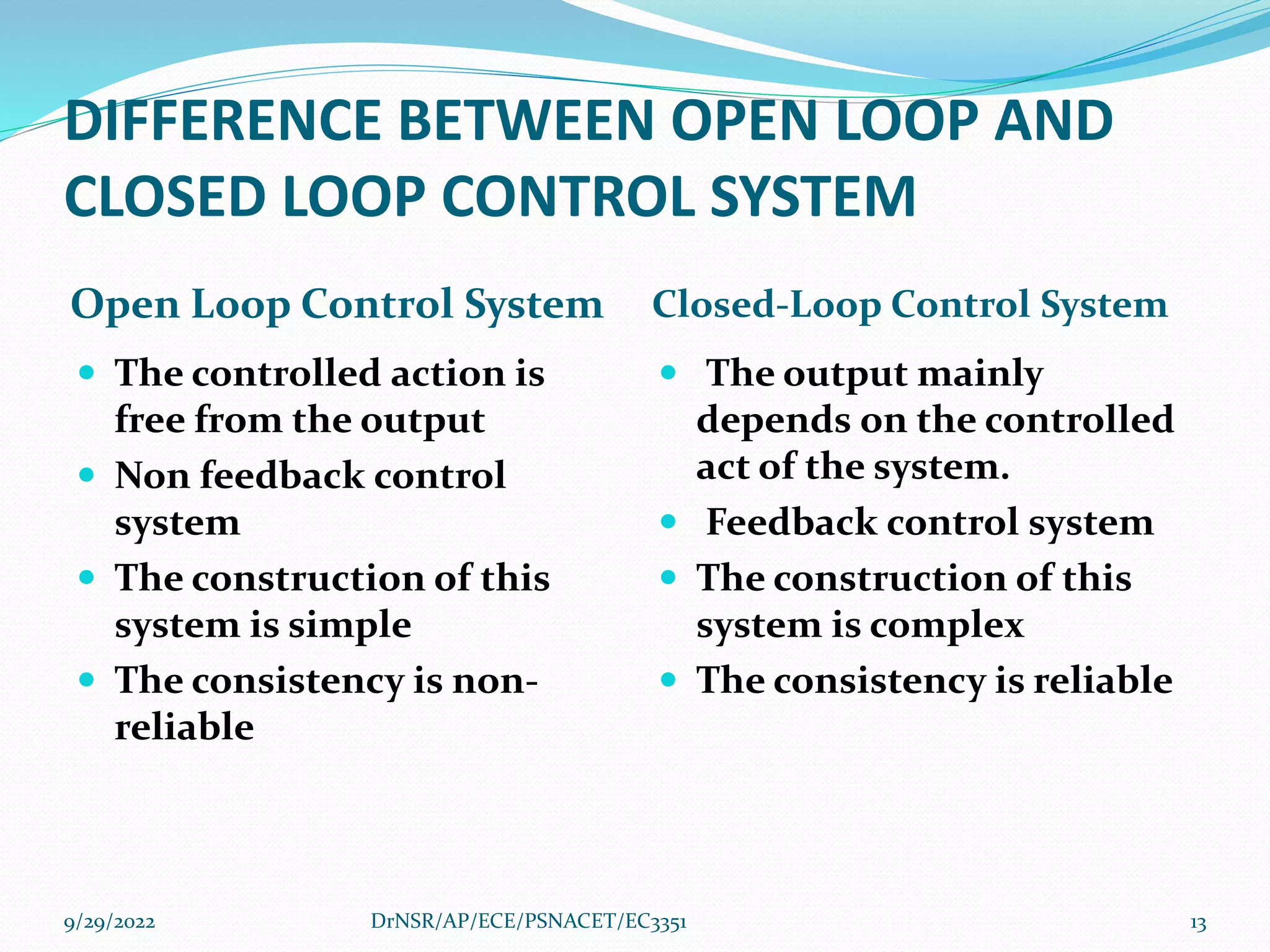
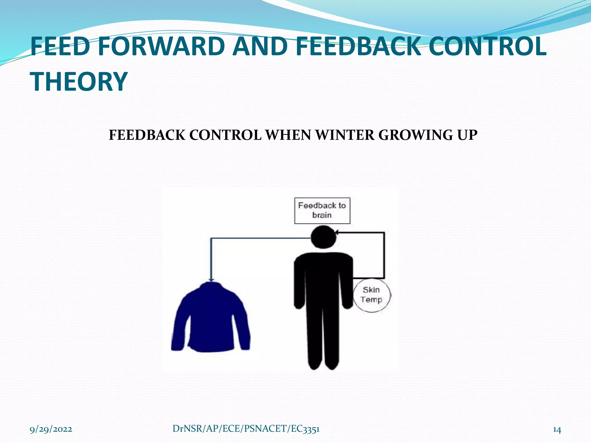
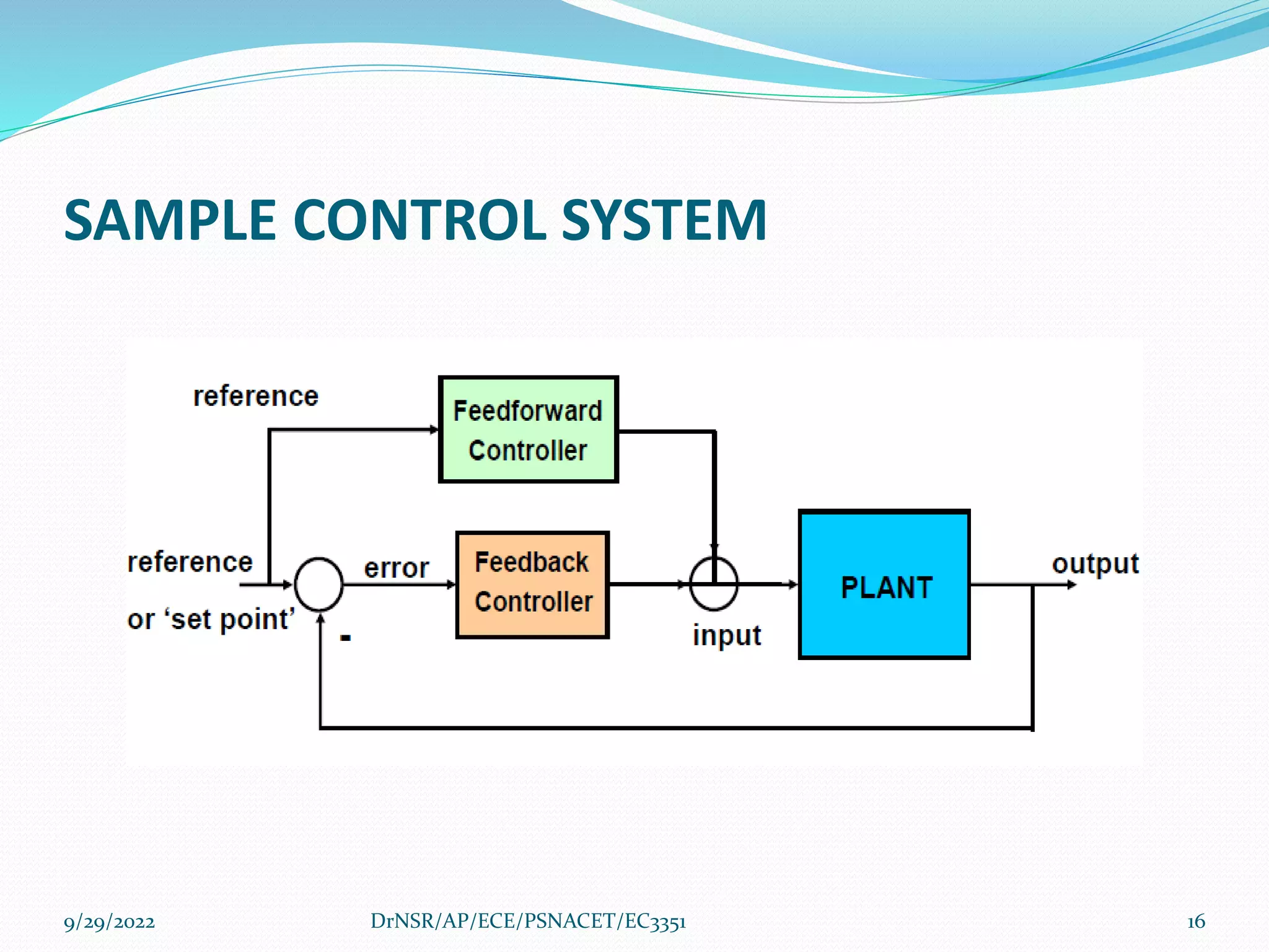
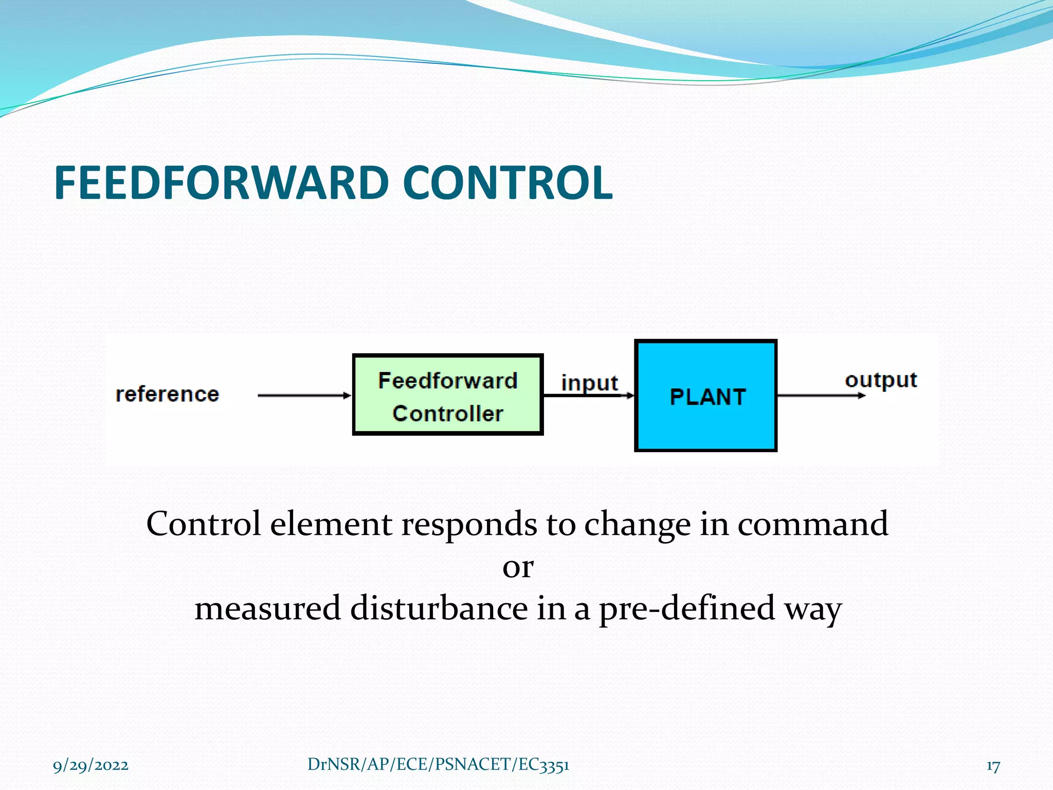
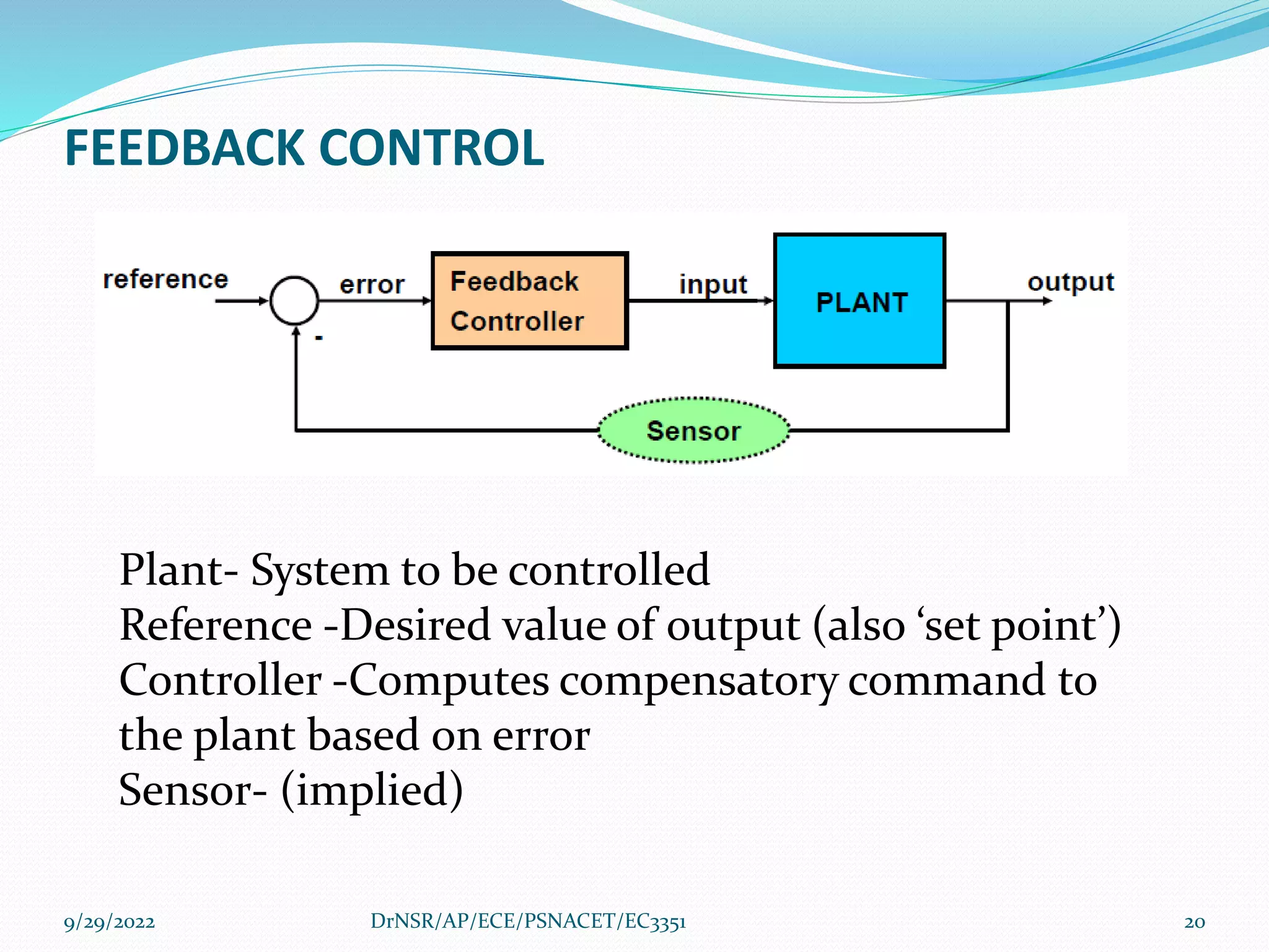
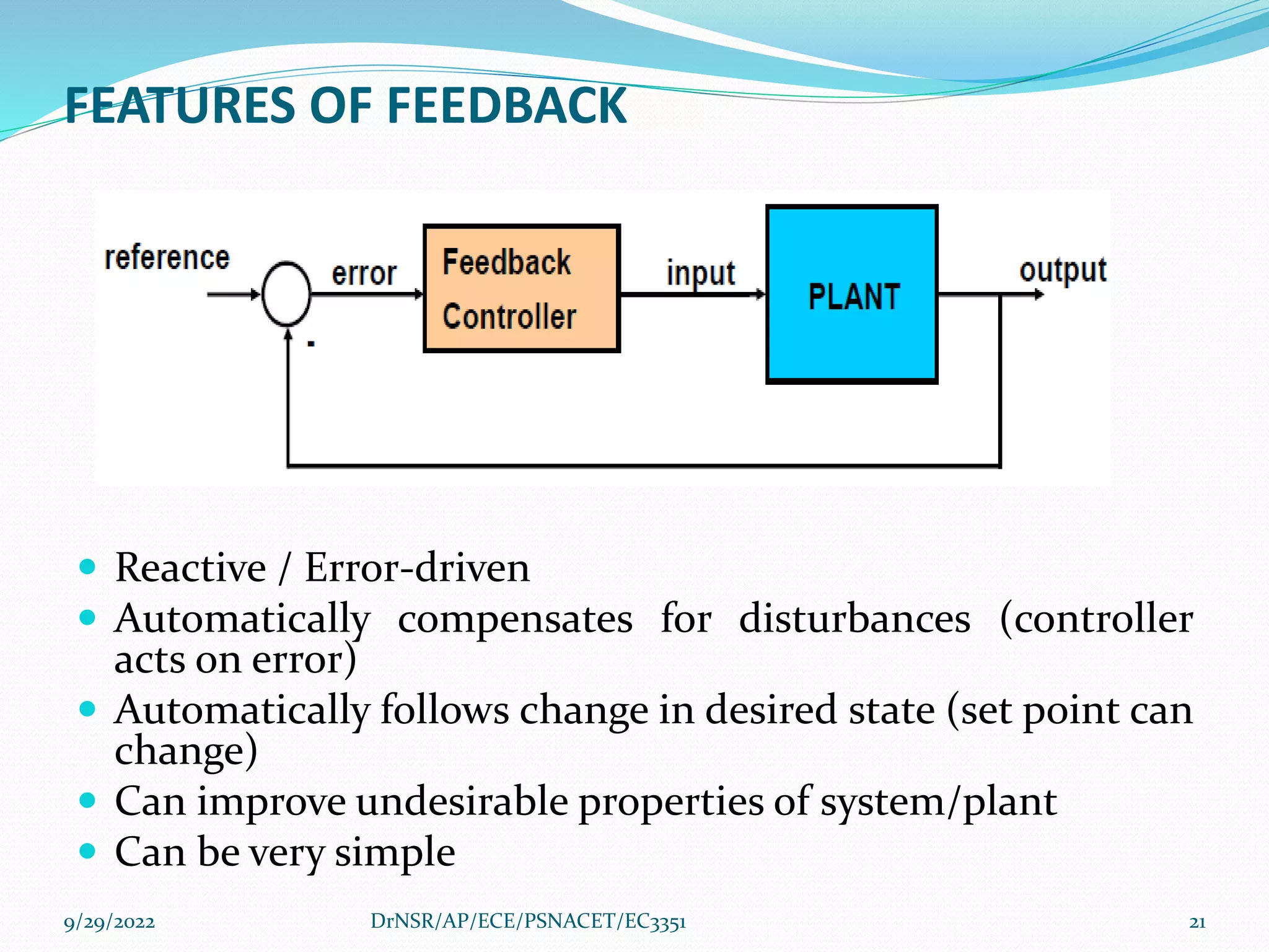
ANNAUNIVERSITY
R2021
COURSE OBJECTIVE
 To introduce the components and their representation
of control systems
 To learn various methods of analyzing
 1.Time response
 2.Frequency response
 3.Stability of the systems
 4.State variable analysis
9/29/2022 2
DrNSR/AP/ECE/PSNACET/EC3351
UNIT I-SYSTEM COMPONENTS AND THEIR
REPRESENTION
 Syllabus
 Control system; terminology and basic structure
 Feed forward and feedback control theory
 Electrical and mechanical transfer function models
 Block diagram models
 Signal flow graph models
 DC and AC servo systems
 Synchros
 Multivariable control system
9/29/2022 3
DrNSR/AP/ECE/PSNACET/EC3351
CONTROL SYSTEM; TERMINOLOGY AND
BASIC STRUCTURE
 Control system theory evolved in the following areas
 1.Engineering
 2.Economy
 3.Socialogy
 4.Biology
 5.Medicine
9/29/2022 4
DrNSR/AP/ECE/PSNACET/EC3351
CONTROL SYSTEM; TERMINOLOGY AND
BASIC STRUCTURE
 Automatic control has become an integral part of
modern manufacturing and industrial processes,
 1.Numerical control of machine tools in
manufacturing industries
 2.Controlling pressure
 3.Temperatre
 4.Humidity
 5.Viscosity
 6.Flow in process industry
9/29/2022 5
DrNSR/AP/ECE/PSNACET/EC3351
CONTROL SYSTEM; TERMINOLOGY AND
BASIC STRUCTURE
System
Group of components are connected in a sequence
to perform a specific function,
the group thus formed is called a system.
9/29/2022 6
DrNSR/AP/ECE/PSNACET/EC3351
CONTROL SYSTEM; TERMINOLOGY AND
BASIC STRUCTURE
 Control system
 In a system ,when the output quantity is
controlled by varying the input quantity, the
system is called control system
9/29/2022 7
DrNSR/AP/ECE/PSNACET/EC3351
OPEN LOOP SYSTEM
 Any physical system which does not automatically
correct the variation in its output is called an open
loop system
9/29/2022 8
DrNSR/AP/ECE/PSNACET/EC3351
9/29/2022 9
DrNSR/AP/ECE/PSNACET/EC3351
CLOSED LOOP SYSTEM
 Control system in which the output has an effect
upon the input quantity in order to maintain the
desired output value are called closed loop system
9/29/2022 10
DrNSR/AP/ECE/PSNACET/EC3351
9/29/2022 11
DrNSR/AP/ECE/PSNACET/EC3351
CLOSED LOOP SYSTEM- CAR DRIVING
9/29/2022 12
DrNSR/AP/ECE/PSNACET/EC3351
DIFFERENCE BETWEEN OPEN LOOP AND
CLOSED LOOP CONTROL SYSTEM
Open Loop Control System Closed-Loop Control System
 The controlled action is
free from the output
 Non feedback control
system
 The construction of this
system is simple
 The consistency is non-
reliable
 The output mainly
depends on the controlled
act of the system.
 Feedback control system
 The construction of this
system is complex
 The consistency is reliable
9/29/2022 13
DrNSR/AP/ECE/PSNACET/EC3351
FEED FORWARD AND FEEDBACK CONTROL
THEORY
FEEDBACK CONTROL WHEN WINTER GROWING UP
9/29/2022 14
DrNSR/AP/ECE/PSNACET/EC3351
FEED FORWARD AND FEEDBACK CONTROL
THEORY
9/29/2022 15
DrNSR/AP/ECE/PSNACET/EC3351
SAMPLE CONTROL SYSTEM
9/29/2022 16
DrNSR/AP/ECE/PSNACET/EC3351
FEEDFORWARD CONTROL
Control element responds to change in command
or
measured disturbance in a pre-defined way
9/29/2022 17
DrNSR/AP/ECE/PSNACET/EC3351
IMPLIMENTATION OF FEEDFORWARD
 Ideally consists of exact inverse model of the plant
 Can compensate for known plant dynamics, delays (before
you get errors)
 No sensors needed
 System response must be predictable
9/29/2022 18
DrNSR/AP/ECE/PSNACET/EC3351
LIMITATIONS OF FEEDFORWARD
 Effects of disturbance or command input must be
predictable
 May not generalize to other conditions
 Will not be accurate if the system changes
9/29/2022 19
DrNSR/AP/ECE/PSNACET/EC3351
FEEDBACK CONTROL
Plant- System to be controlled
Reference -Desired value of output (also ‘set point’)
Controller -Computes compensatory command to
the plant based on error
Sensor- (implied)
9/29/2022 20
DrNSR/AP/ECE/PSNACET/EC3351
FEATURES OF FEEDBACK
 Reactive / Error-driven
 Automatically compensates for disturbances (controller
acts on error)
 Automatically follows change in desired state (set point can
change)
 Can improve undesirable properties of system/plant
 Can be very simple
9/29/2022 21
DrNSR/AP/ECE/PSNACET/EC3351
COMBINING FEEDBACK AND FEEDFORWARD
 Feed forward component provides rapid response
 Feedback component fills in the rest of the
response accurately, compensating for errors in
the model
9/29/2022 22
DrNSR/AP/ECE/PSNACET/EC3351
ELECTRICAL AND MECHANICAL TRANSFER
FUNCTION MODELS
 The control systems can be represented with a set of
mathematical equations known as mathematical
model.
 These models are useful for analysis and design of
control systems.
9/29/2022 DrNSR/AP/ECE/PSNACET/EC3351 23
ELECTRICAL AND MECHANICAL TRANSFER
FUNCTION MODELS
 Analysis of control system means finding the output
when we know the input and mathematical model.
 Design of control system means finding the
mathematical model when we know the input and the
output
9/29/2022 DrNSR/AP/ECE/PSNACET/EC3351 24
ELECTRICAL AND MECHANICAL TRANSFER
FUNCTION MODELS
 The following mathematical models are mostly used.
 1. Differential equation model
 2. Transfer function model
 3. State space model
9/29/2022 DrNSR/AP/ECE/PSNACET/EC3351 25
DIFFERENTIAL EQUATION MODEL
Differential equation model is a time domain
mathematical model of control systems.
9/29/2022 DrNSR/AP/ECE/PSNACET/EC3351 26
9/29/2022 DrNSR/AP/ECE/PSNACET/EC3351 27
RLC series electrical system
Mesh equation for this circuit is
9/29/2022 DrNSR/AP/ECE/PSNACET/EC3351 28
 Substitute, the current passing through capacitor
The above equation is a second order differential equation.
TRANSFER FUNCTION MODEL
 Transfer function model is an s-domain mathematical
model of control systems.
9/29/2022 DrNSR/AP/ECE/PSNACET/EC3351 29
TRANSFER FUNCTION MODEL
 The Transfer function of a Linear Time Invariant
(LTI) system is defined as the ratio of Laplace
transform of output and Laplace transform of
input by assuming all the initial conditions are
zero.
9/29/2022 DrNSR/AP/ECE/PSNACET/EC3351 30
transfer function model
TRANSFER FUNCTION OF RLC SERIES ELECTRICAL
SYSTEM
RLC series circuit
Transfer function model of
RLC series circuit
9/29/2022 DrNSR/AP/ECE/PSNACET/EC3351 31
second order electrical system with a
block having the transfer function inside
it. And this block has an input Vi(s) & an
output Vo(s).
THE DIFFERENTIAL EQUATION MODELING OF
MECHANICAL SYSTEMS.
 There are two types of mechanical systems based
on the type of motion.
 1. Translational mechanical systems
 2.Rotational mechanical systems
9/29/2022 DrNSR/AP/ECE/PSNACET/EC3351 32
MODELING OF TRANSLATIONAL MECHANICAL
SYSTEMS
 Translational mechanical systems move along a
straight line
 These systems mainly consist of three basic
elements.
 Mass,
 Spring
 Dashpot or damper.
9/29/2022 DrNSR/AP/ECE/PSNACET/EC3351 33
MASS
9/29/2022 DrNSR/AP/ECE/PSNACET/EC3351 34
BLOCK DIAGRAM OF MASS
MASS
 Mass is the property of a body,
 which stores kinetic energy.
 If a force is applied on a body having mass M, then
it is opposed by an opposing force due to mass.
 This opposing force is proportional to the
acceleration of the body.
 Assume elasticity and frictions are negligible.
9/29/2022 DrNSR/AP/ECE/PSNACET/EC3351 35
9/29/2022 DrNSR/AP/ECE/PSNACET/EC3351 36
 Where,
 F is the applied force
 Fm is the opposing force due to mass
 M is mass
 a is acceleration
 x is displacement
9/29/2022 DrNSR/AP/ECE/PSNACET/EC3351 37
SPRING
9/29/2022 DrNSR/AP/ECE/PSNACET/EC3351 38
BLOCK DIAGRAM OF SPRING
 Spring is an element,
 which stores potential energy.
 If a force is applied on spring K, then it is opposed
by an opposing force due to elasticity of spring.
 This opposing force is proportional to the
displacement of the spring.
 Assume mass and friction are negligible.
9/29/2022 DrNSR/AP/ECE/PSNACET/EC3351 39
 Where,
 F is the applied force
 Fk is the opposing
force due to elasticity
of spring
 K is spring constant
 x is displacement
9/29/2022 DrNSR/AP/ECE/PSNACET/EC3351 40
DASHPOT
9/29/2022 DrNSR/AP/ECE/PSNACET/EC3351 41
BLOCK DIAGRAM OF FRICTION
 If a force is applied on dashpot B,
 then it is opposed by an opposing force due to
friction of the dashpot.
 This opposing force is proportional to the velocity
of the body.
 Assume mass and elasticity are negligible.
9/29/2022 DrNSR/AP/ECE/PSNACET/EC3351 42
 Where,
 Fb is the opposing
force due to friction of
dashpot
 B is the frictional
coefficient
 v is velocity
 x is displacement
9/29/2022 DrNSR/AP/ECE/PSNACET/EC3351 43
MODELING OF ROTATIONAL MECHANICAL
SYSTEMS
 Rotational mechanical systems move about a
fixed axis.
 These systems mainly consist of three basic
elements. Those are
 Moment of inertia,
 Torsional spring
 Dashpot.
9/29/2022 DrNSR/AP/ECE/PSNACET/EC3351 44
Moment of Inertia
9/29/2022 DrNSR/AP/ECE/PSNACET/EC3351 45
BLOCK DIAGRAM OF MOMENT OF INERTIA
 If a torque is applied to a rotational mechanical
system,
 then it is opposed by opposing torques due to
moment of inertia, elasticity and friction of the
system.
 Since the applied torque and the opposing
torques are in opposite directions,
 the algebraic sum of torques acting on the system
is zero.
9/29/2022 DrNSR/AP/ECE/PSNACET/EC3351 46
Where,
 T is the applied torque
 Tj is the opposing torque
due to moment of
inertia
 J is moment of inertia
 α is angular acceleration
 θ is angular
displacement
9/29/2022 DrNSR/AP/ECE/PSNACET/EC3351 47
Torsional spring
9/29/2022 DrNSR/AP/ECE/PSNACET/EC3351 48
 Rotational mechanical system, torsional spring
stores potential energy.
 If a torque is applied on torsional spring K, then it
is opposed by an opposing torque due to the
elasticity of torsional spring.
 This opposing torque is proportional to the
angular displacement of the torsional spring.
 Assume that the moment of inertia and friction are
negligible.
9/29/2022 DrNSR/AP/ECE/PSNACET/EC3351 49
 Where,
 T is the applied torque
 Tk is the opposing
torque due to elasticity
of torsional spring
 K is the torsional
spring constant
 θ is angular
displacement
9/29/2022 DrNSR/AP/ECE/PSNACET/EC3351 50
Dashpot
9/29/2022 DrNSR/AP/ECE/PSNACET/EC3351 51
 If a torque is applied on dashpot B, then it is
opposed by an opposing torque due to the
rotational friction of the dashpot.
 This opposing torque is proportional to the
angular velocity of the body.
 Assume the moment of inertia and elasticity are
negligible.
9/29/2022 DrNSR/AP/ECE/PSNACET/EC3351 52
PROBLEMS
1.Write the differential equations governing the
mechanical system shown in fig, and determine the
transfer function (X(s)/F(s))
9/29/2022 DrNSR/AP/ECE/PSNACET/EC3351 53
9/29/2022 DrNSR/AP/ECE/PSNACET/EC3351 54
9/29/2022 DrNSR/AP/ECE/PSNACET/EC3351 55
9/29/2022 DrNSR/AP/ECE/PSNACET/EC3351 56
9/29/2022 DrNSR/AP/ECE/PSNACET/EC3351 57
2.Write the differential equations governing the
mechanical system shown in the fig, and determine
the transfer function
9/29/2022 DrNSR/AP/ECE/PSNACET/EC3351 58
9/29/2022 DrNSR/AP/ECE/PSNACET/EC3351 59
9/29/2022 DrNSR/AP/ECE/PSNACET/EC3351 60
9/29/2022 DrNSR/AP/ECE/PSNACET/EC3351 61
9/29/2022 DrNSR/AP/ECE/PSNACET/EC3351 62
9/29/2022 DrNSR/AP/ECE/PSNACET/EC3351 63
9/29/2022 DrNSR/AP/ECE/PSNACET/EC3351 64
9/29/2022 DrNSR/AP/ECE/PSNACET/EC3351 65
9/29/2022 DrNSR/AP/ECE/PSNACET/EC3351 66
9/29/2022 DrNSR/AP/ECE/PSNACET/EC3351 67
Substituting X1(S) from node 1
9/29/2022 DrNSR/AP/ECE/PSNACET/EC3351 68
DC AND AC SERVO SYSTEMS
 A DC servo system is constructed by using DC
motor which has armature and field winding
coupled with gearbox, controller and
Potentiometer,
 AC servo system is constructed using an Induction
motor consisting of rotor and stator with gear
system and Encoders.
9/29/2022 DrNSR/AP/ECE/PSNACET/EC3351 69
9/29/2022 DrNSR/AP/ECE/PSNACET/EC3351 70
What is servomotor
 Servo is an electromagnetic device uses a negative
feedback mechanism to converts an electric signal
into controlled motion.
9/29/2022 DrNSR/AP/ECE/PSNACET/EC3351 71
DC AND AC SERVOSYSTEMS
 TYPES
 1.DC SERVO MOTORS
 2.AC SERVO MOTORS
9/29/2022 DrNSR/AP/ECE/PSNACET/EC3351 72
DC SERVO MOTORS
9/29/2022 DrNSR/AP/ECE/PSNACET/EC3351 73
 Servo motor is basically a closed loop feedback
system.
 A closed loop feedback system controls the
output of the system by varying input
9/29/2022 DrNSR/AP/ECE/PSNACET/EC3351 74
9/29/2022 DrNSR/AP/ECE/PSNACET/EC3351 75
9/29/2022 DrNSR/AP/ECE/PSNACET/EC3351 76
CONSTRUCTION OF DC
SERVOMOTOR
 Stator Winding: This type of winding wound on the
stationary part of the motor. It is also known as field
winding of the motor.
 Rotor Winding: This type of winding wound on the
rotating part of the motor. It is also known as an
armature winding of the motor.
9/29/2022 DrNSR/AP/ECE/PSNACET/EC3351 77
 Bearing: These are of two types,i.e, font bearing and
back bearing which are used for the movement of the
shaft.
 Shaft: The armature winding is coupled on the iron
rod is known as the shaft of the motor.
 Encoder: It has the approximate sensor which
determines the rotational speed of motor and
revolution per minute of the motor.
9/29/2022 DrNSR/AP/ECE/PSNACET/EC3351 78
AC SERVOMOTOR
9/29/2022 DrNSR/AP/ECE/PSNACET/EC3351 79
9/29/2022 DrNSR/AP/ECE/PSNACET/EC3351 80
TORQUE –SPEED CHARACTERISTICS
WITH ROTOR RESISTNCE
9/29/2022 DrNSR/AP/ECE/PSNACET/EC3351 81
TORQUE-SPEED CHARACTERISTICS
9/29/2022 DrNSR/AP/ECE/PSNACET/EC3351 82
APPLICATIONS
 Robotics.
 Installed in cameras to adjust the focus for
obtaining better quality images
 Used to track the direction of the sun in solar
panels
 Textile industries in knitting the fabrics
 Aircraft for balancing.
9/29/2022 DrNSR/AP/ECE/PSNACET/EC3351 83
SYNCHROS
 The Synchro is a type of transducer
 which transforms the angular position of the
shaft into an electric signal.
 It is used as an error detector and as a rotary
position sensor.
9/29/2022 DrNSR/AP/ECE/PSNACET/EC3351 84
SYNCHROS
 The error occurs in the system because of the
misalignment of the shaft.
 The transmitter and the control transformer are
the two main parts of the synchro.
9/29/2022 DrNSR/AP/ECE/PSNACET/EC3351 85
SYNCHROS SYSTEM TYPES
 1.Control Type Synchro.
 2.Torque Transmission Type Synchro.
9/29/2022 DrNSR/AP/ECE/PSNACET/EC3351 86
CONTROL TYPE SYNCHRO
 The control type Synchro is used for driving the
large loads.
9/29/2022 DrNSR/AP/ECE/PSNACET/EC3351 87
TORQUE TRANSMISSION TYPE SYNCHROS
 This type of synchros has small output torque,
 Used for running the very light load like a
pointer.
9/29/2022 DrNSR/AP/ECE/PSNACET/EC3351 88
CONTROL TYPE SYNCHROS SYSTEM
 The controls synchros is used for error detection
in positional control systems. Their systems
consist two units. They are
 1.Synchro Transmitter
 2.Synchro receiver
9/29/2022 DrNSR/AP/ECE/PSNACET/EC3351 89
Synchros Transmitter
 Their construction is similar to the three phase
alternator.
 The stator of the synchros is made of steel for
reducing the iron losses.
 The stator is slotted for housing the three phase
windings.
 The axis of the stator winding is kept 120º apart
from each other.
9/29/2022 DrNSR/AP/ECE/PSNACET/EC3351 90
9/29/2022 DrNSR/AP/ECE/PSNACET/EC3351 91
9/29/2022 DrNSR/AP/ECE/PSNACET/EC3351 92
 The AC voltage is applied to the rotor of the
transmitter and it is expressed as
9/29/2022 DrNSR/AP/ECE/PSNACET/EC3351 93
 The coils of the stator windings are connected in
star.
 The rotor of the synchros is a dumb bell in shape,
and a concentric coil is wound on it.
 The AC voltage is applied to the rotor with the
help of slip rings.
9/29/2022 DrNSR/AP/ECE/PSNACET/EC3351 94
9/29/2022 DrNSR/AP/ECE/PSNACET/EC3351 95
9/29/2022 DrNSR/AP/ECE/PSNACET/EC3351 96
9/29/2022 DrNSR/AP/ECE/PSNACET/EC3351 97
MULTIVARIABLE CONTROL SYSTEM
 Multivariable control system in which the
variable interacts strongly.
 This kind of system must have more than one
input and more than one output.
 A disturbance in any input causes a change of
response from at least one output.
9/29/2022 DrNSR/AP/ECE/PSNACET/EC3351 98
MULTIVARIABLE CONTROL SYSTEM
9/29/2022 DrNSR/AP/ECE/PSNACET/EC3351 99
MULTIVARIABLE CONTROL SYSTEM
 This kind of system have as many inputs and
outputs as needed to control the process.
 A system with an equal number of inputs and
outputs is said to be square.
9/29/2022 DrNSR/AP/ECE/PSNACET/EC3351 100
APPLICATIONS
 A heated liquid tank where both the level and the
temperature shall be controlled.
 A distillation column where the top and bottom
concentration shall be controlled.
 A robot manipulator where the positions of the
manipulators (arms)shall be controlled.
 A chemical reactor where the concentration and
the temperature shall be controlled.
9/29/2022 DrNSR/AP/ECE/PSNACET/EC3351 101
SIGNAL FLOW GRAPH MODELS
 Signal flow graph is used to represent the control
system graphically
 Signal flow graph is a diagram which represents a
set of simultaneous equations
9/29/2022 DrNSR/AP/ECE/PSNACET/EC3351 102
SIGNAL FLOW GRAPH MODELS
 Signal flow graph of control system is further
simplification of block diagram of control system
 Blocks of transfer function, summing symbols
and take off points are eliminated by branches
and nodes.
9/29/2022 DrNSR/AP/ECE/PSNACET/EC3351 103
Terms used in Signal Flow Graph
 Node
 Input node or source
 Output node or sink
 Mixed node
 Branch
 Transmittance
 Forward path
 Feedback loop
9/29/2022 DrNSR/AP/ECE/PSNACET/EC3351 104
 Self-loop
 Path gain
 Loop gain
 Non-touching loops:
9/29/2022 DrNSR/AP/ECE/PSNACET/EC3351 105
BLOCK DIAGRAM AND SIGNAL FLOW
GRAPH
9/29/2022 DrNSR/AP/ECE/PSNACET/EC3351 106
Properties of signal flow graph
 The signal from a node to other flows through the
branch in the direction of arrowhead.
 The graphical method is valid only for linear time-
invariant systems.
 The signal flowing through a branch is multiplied by
the gain or transmittance of that branch. This product
is equivalent to the node where that branch is
terminating.
9/29/2022 DrNSR/AP/ECE/PSNACET/EC3351 107
SFG from system equations
9/29/2022 DrNSR/AP/ECE/PSNACET/EC3351 108
9/29/2022 DrNSR/AP/ECE/PSNACET/EC3351 109
SFG from Block Diagram
9/29/2022 DrNSR/AP/ECE/PSNACET/EC3351 110
9/29/2022 DrNSR/AP/ECE/PSNACET/EC3351 111
Mason’s Gain Formula
 Suppose there are ‘N’ forward paths in a signal
flow graph. The gain between the input and the
output nodes of a signal flow graph is nothing but
the transfer function of the system.
 It can be calculated by using Mason’s gain
formula.
9/29/2022 DrNSR/AP/ECE/PSNACET/EC3351 112
Mason’s Gain Formula
9/29/2022 DrNSR/AP/ECE/PSNACET/EC3351 113
Mason’s Gain Formula
9/29/2022 DrNSR/AP/ECE/PSNACET/EC3351 114
Block diagram
Transfer Function: Ratio between transformation of output to the transformation of
input when all the initial conditions are zero.
A Block diagram is basically modelling of any simple or complex system.
It Consists of multiple Blocks connected together to represent a system to explain
how it is functioning
)
(s
R
2
G 3
G
1
G
4
G
1
H
2
H
)
(s
Y
)
(s
G
)
(s
C
)
(s
R G(s)=C(s)/R(s)
Simple system:
Complex System:
• It is normally required to reduce multiple
blocks into single block or for convenient
understanding it may sometimes required to
rearrange the blocks from its original order.
• For the calculation of Transfer function its
required to be reduced.
NEED FOR BLOCK DIAGRAM
REDUCTION
Block Diagram Reduction techniques
2
G
1
G 2
1G
G
2. Moving a summing point behind a block
G G
G
1
G
2
G
2
1 G
G 
1. Combining blocks which are in cascade or in parallel
5. Moving a pickoff point ahead of a block
G G
G G
G
1
G
3. Moving a summing point ahead of a block
G G
G
1
4. Moving a pickoff point behind a block
6. Eliminating a feedback loop
G
H
GH
G

1
7. Swapping with two adjacent summing points
A B A
B
G
1

H
G
G

1
1−Check for the blocks connected in series and
simplify. RULE NO-1
2−Check for the blocks connected in parallel
and simplify. RULE NO-1
3−Check for the blocks connected in feedback
loop and simplify. RULE NO-6
4− If there is difficulty with take-off point while
simplifying, shift it towards right. RULE NO-4,5
5−If there is difficulty with summing point
while simplifying, shift it towards left. RULE NO-2,3
6-Repeat the above steps till you get the
simplified form, i.e., single block.
Example 1
Find the transfer function of the following block diagrams
2
G 3
G
1
G
4
G
1
H
2
H
)
(s
Y
)
(s
R
(a)
1. Apply the rule that Moving pickoff/takeoff point ahead of block
2. Eliminate loop I & simplify as
3
2
4 G
G
G 
B
1
G
2
H
)
(s
Y
4
G
2
G
1
H
A
B
3
G
2
G
)
(s
R
I
Solution:
2
G
3. Moving pickoff point B behind block
3
2
4 G
G
G 
1
G
B
)
(s
R
2
1G
H 2
H
)
(s
Y
)
/(
1 3
2
4 G
G
G 
II
1
G
B
)
(s
R C
3
2
4 G
G
G 
2
H
)
(s
Y
2
1G
H
4
G
2
G A
3
G 3
2
4 G
G
G 
4. Eliminate loop III
)
(s
R
)
(
1
)
(
3
2
4
2
1
2
1
3
2
4
1
G
G
G
H
H
G
G
G
G
G
G



 )
(s
Y
)
(
)
(
1
)
(
)
(
)
(
)
(
3
2
4
1
3
2
4
2
1
2
1
3
2
4
1
G
G
G
G
G
G
G
H
H
G
G
G
G
G
G
s
R
s
Y
s
T








)
(s
R
1
G
C
3
2
4
1
2
G
G
G
H
G

)
(s
Y
3
2
4 G
G
G 
2
H
C
)
(
1 3
2
4
2
3
2
4
G
G
G
H
G
G
G



Using rule 6
2
G
1
G
1
H 2
H
)
(s
R )
(s
Y
3
H
(b) Find the transfer function of the following block diagram
Solution:
1. Eliminate loop I
2. Moving pickoff point A behind block
2
2
2
1 H
G
G

1
G
1
H
)
(s
R )
(s
Y
3
H
B
A
2
2
2
1 H
G
G

2
2
2
1
G
H
G

1
G
1
H
)
(s
R )
(s
Y
3
H
2
G
2
H
B
A
II
I
2
2
2
1 H
G
G

Not a feedback loop
)
1
(
2
2
2
1
3
G
H
G
H
H


3. Eliminate loop II
)
(s
R )
(s
Y
2
2
2
1
1 H
G
G
G

2
2
2
1
3
)
1
(
G
H
G
H
H


2
1
2
1
1
1
3
2
1
2
2
2
1
1
)
(
)
(
)
(
H
H
G
G
H
G
H
G
G
H
G
G
G
s
R
s
Y
s
T






Using rule 6
2
G 4
G
1
G
4
H
2
H
3
H
)
(s
Y
)
(s
R
3
G
1
H
(c) Find the transfer function of the following block diagrams
Solution:
2
G 4
G
1
G
4
H
)
(s
Y
3
G
1
H
2
H
)
(s
R
A B
3
H
4
1
G
4
1
G
I
1. Moving pickoff point A behind block
4
G
4
3
G
H
4
2
G
H
Solution:
2
G 4
G
1
G
4
H
)
(s
Y
3
G
1
H
2
H
)
(s
R
A B
3
H
4
1
G
4
1
G
I
1. Moving pickoff point A behind block
4
G
4
3
G
H
4
2
G
H
Solution:
2
G
1
G
4
H
)
(s
Y
4
3G
G
1
H
2
H
)
(s
R
B
3
H
4
1
G
4
1
G
I
1. Moving pickoff point A behind block
4
G
4
3
G
H
4
2
G
H
Solution:
2
G
1
G
)
(s
Y
1
H
2
H
)
(s
R
B
3
H
4
1
G
4
1
G
I
1. Moving pickoff point A behind block
4
G
4
3
G
H
4
2
G
H
2
4
4
3
4
3
1 H
G
G
G
G

2. Eliminate loop I and Simplify
II
III
4
4
3
4
3
2
1 H
G
G
G
G
G

1
G
)
(s
Y
1
H
B
4
2
G
H
)
(s
R
4
3
G
H
II
3
3
2
4
4
3
4
3
2
1 H
G
G
H
G
G
G
G
G


III
4
1
4
2
G
H
G
H 
Not feedback
feedback
)
(s
R )
(s
Y
4
1
4
2
G
H
G
H 
3
3
2
4
4
3
4
3
2
1
1 H
G
G
H
G
G
G
G
G
G


3. Eliminate loop II & III
1
4
3
2
1
2
3
2
1
4
4
3
3
3
2
4
3
2
1
1
)
(
)
(
)
(
H
G
G
G
G
H
G
G
G
H
G
G
H
G
G
G
G
G
G
s
R
s
Y
s
T






Using rule 6
3
G
1
G
1
H
2
H
)
(s
R )
(s
Y
4
G
2
G A
B
(d)
Find the transfer function of the following block diagram
Solution:
1. Moving pickoff point A behind block
3
G
I
1
H
3
1
G
)
(s
Y
1
G
1
H
2
H
)
(s
R
4
G
2
G
A B
3
1
G
3
G
2. Eliminate loop I & Simplify
3
G
1
H
2
G B
3
1
G
2
H
3
2G
G B
2
3
1
H
G
H

1
G
)
(s
R )
(s
Y
4
G
3
1
G
H
2
3
2
1
2
3
2
1 H
G
G
H
G
G
G


II
)
(s
R )
(s
Y
1
2
1
2
3
2
1
2
3
2
1
1 H
G
G
H
G
G
H
G
G
G
G



3. Eliminate loop II
1
2
1
2
3
2
1
2
3
2
1
4
1
)
(
)
(
)
(
H
G
G
H
G
G
H
G
G
G
G
G
s
R
s
Y
s
T






4
G
Find the transfer function of the following block diagram
Step 1 − Use Rule 1 for blocks G1and G2. Use Rule 2 for
blocks G3 and G4. The modified block diagram is shown in the
following figure.
Step 2 − Use Rule 3 for blocks G1G2 and H1. Use Rule 4 for
shifting take-off point after the block G5.
The modified block diagram is shown in the following figure.
Step 3 − Use Rule 1 for blocks (G3+G4) and G5.
The modified block diagram is shown in the
following figure.
Step 4 − Use Rule 3 for blocks (G3+G4)G5 and H3.
The modified block diagram is shown in the following
figure.
Step 5 − Use Rule 1 for blocks connected in
series. The modified block diagram is shown
in the following figure.
Step 6 − Use Rule 3 for blocks connected in
feedback loop. The modified block diagram is
shown in the following figure. This is the
simplified block diagram.
9/29/2022 DrNSR/AP/ECE/PSNACET/EC3351 147

UNIT I CONTROL SYSTEM (EC3351).pptx

  • 1.
  • 2.
    COURSE OBJECTIVE  Tointroduce the components and their representation of control systems  To learn various methods of analyzing  1.Time response  2.Frequency response  3.Stability of the systems  4.State variable analysis 9/29/2022 2 DrNSR/AP/ECE/PSNACET/EC3351
  • 3.
    UNIT I-SYSTEM COMPONENTSAND THEIR REPRESENTION  Syllabus  Control system; terminology and basic structure  Feed forward and feedback control theory  Electrical and mechanical transfer function models  Block diagram models  Signal flow graph models  DC and AC servo systems  Synchros  Multivariable control system 9/29/2022 3 DrNSR/AP/ECE/PSNACET/EC3351
  • 4.
    CONTROL SYSTEM; TERMINOLOGYAND BASIC STRUCTURE  Control system theory evolved in the following areas  1.Engineering  2.Economy  3.Socialogy  4.Biology  5.Medicine 9/29/2022 4 DrNSR/AP/ECE/PSNACET/EC3351
  • 5.
    CONTROL SYSTEM; TERMINOLOGYAND BASIC STRUCTURE  Automatic control has become an integral part of modern manufacturing and industrial processes,  1.Numerical control of machine tools in manufacturing industries  2.Controlling pressure  3.Temperatre  4.Humidity  5.Viscosity  6.Flow in process industry 9/29/2022 5 DrNSR/AP/ECE/PSNACET/EC3351
  • 6.
    CONTROL SYSTEM; TERMINOLOGYAND BASIC STRUCTURE System Group of components are connected in a sequence to perform a specific function, the group thus formed is called a system. 9/29/2022 6 DrNSR/AP/ECE/PSNACET/EC3351
  • 7.
    CONTROL SYSTEM; TERMINOLOGYAND BASIC STRUCTURE  Control system  In a system ,when the output quantity is controlled by varying the input quantity, the system is called control system 9/29/2022 7 DrNSR/AP/ECE/PSNACET/EC3351
  • 8.
    OPEN LOOP SYSTEM Any physical system which does not automatically correct the variation in its output is called an open loop system 9/29/2022 8 DrNSR/AP/ECE/PSNACET/EC3351
  • 9.
  • 10.
    CLOSED LOOP SYSTEM Control system in which the output has an effect upon the input quantity in order to maintain the desired output value are called closed loop system 9/29/2022 10 DrNSR/AP/ECE/PSNACET/EC3351
  • 11.
  • 12.
    CLOSED LOOP SYSTEM-CAR DRIVING 9/29/2022 12 DrNSR/AP/ECE/PSNACET/EC3351
  • 13.
    DIFFERENCE BETWEEN OPENLOOP AND CLOSED LOOP CONTROL SYSTEM Open Loop Control System Closed-Loop Control System  The controlled action is free from the output  Non feedback control system  The construction of this system is simple  The consistency is non- reliable  The output mainly depends on the controlled act of the system.  Feedback control system  The construction of this system is complex  The consistency is reliable 9/29/2022 13 DrNSR/AP/ECE/PSNACET/EC3351
  • 14.
    FEED FORWARD ANDFEEDBACK CONTROL THEORY FEEDBACK CONTROL WHEN WINTER GROWING UP 9/29/2022 14 DrNSR/AP/ECE/PSNACET/EC3351
  • 15.
    FEED FORWARD ANDFEEDBACK CONTROL THEORY 9/29/2022 15 DrNSR/AP/ECE/PSNACET/EC3351
  • 16.
    SAMPLE CONTROL SYSTEM 9/29/202216 DrNSR/AP/ECE/PSNACET/EC3351
  • 17.
    FEEDFORWARD CONTROL Control elementresponds to change in command or measured disturbance in a pre-defined way 9/29/2022 17 DrNSR/AP/ECE/PSNACET/EC3351
  • 18.
    IMPLIMENTATION OF FEEDFORWARD Ideally consists of exact inverse model of the plant  Can compensate for known plant dynamics, delays (before you get errors)  No sensors needed  System response must be predictable 9/29/2022 18 DrNSR/AP/ECE/PSNACET/EC3351
  • 19.
    LIMITATIONS OF FEEDFORWARD Effects of disturbance or command input must be predictable  May not generalize to other conditions  Will not be accurate if the system changes 9/29/2022 19 DrNSR/AP/ECE/PSNACET/EC3351
  • 20.
    FEEDBACK CONTROL Plant- Systemto be controlled Reference -Desired value of output (also ‘set point’) Controller -Computes compensatory command to the plant based on error Sensor- (implied) 9/29/2022 20 DrNSR/AP/ECE/PSNACET/EC3351
  • 21.
    FEATURES OF FEEDBACK Reactive / Error-driven  Automatically compensates for disturbances (controller acts on error)  Automatically follows change in desired state (set point can change)  Can improve undesirable properties of system/plant  Can be very simple 9/29/2022 21 DrNSR/AP/ECE/PSNACET/EC3351
  • 22.
    COMBINING FEEDBACK ANDFEEDFORWARD  Feed forward component provides rapid response  Feedback component fills in the rest of the response accurately, compensating for errors in the model 9/29/2022 22 DrNSR/AP/ECE/PSNACET/EC3351
  • 23.
    ELECTRICAL AND MECHANICALTRANSFER FUNCTION MODELS  The control systems can be represented with a set of mathematical equations known as mathematical model.  These models are useful for analysis and design of control systems. 9/29/2022 DrNSR/AP/ECE/PSNACET/EC3351 23
  • 24.
    ELECTRICAL AND MECHANICALTRANSFER FUNCTION MODELS  Analysis of control system means finding the output when we know the input and mathematical model.  Design of control system means finding the mathematical model when we know the input and the output 9/29/2022 DrNSR/AP/ECE/PSNACET/EC3351 24
  • 25.
    ELECTRICAL AND MECHANICALTRANSFER FUNCTION MODELS  The following mathematical models are mostly used.  1. Differential equation model  2. Transfer function model  3. State space model 9/29/2022 DrNSR/AP/ECE/PSNACET/EC3351 25
  • 26.
    DIFFERENTIAL EQUATION MODEL Differentialequation model is a time domain mathematical model of control systems. 9/29/2022 DrNSR/AP/ECE/PSNACET/EC3351 26
  • 27.
    9/29/2022 DrNSR/AP/ECE/PSNACET/EC3351 27 RLCseries electrical system Mesh equation for this circuit is
  • 28.
    9/29/2022 DrNSR/AP/ECE/PSNACET/EC3351 28 Substitute, the current passing through capacitor The above equation is a second order differential equation.
  • 29.
    TRANSFER FUNCTION MODEL Transfer function model is an s-domain mathematical model of control systems. 9/29/2022 DrNSR/AP/ECE/PSNACET/EC3351 29
  • 30.
    TRANSFER FUNCTION MODEL The Transfer function of a Linear Time Invariant (LTI) system is defined as the ratio of Laplace transform of output and Laplace transform of input by assuming all the initial conditions are zero. 9/29/2022 DrNSR/AP/ECE/PSNACET/EC3351 30 transfer function model
  • 31.
    TRANSFER FUNCTION OFRLC SERIES ELECTRICAL SYSTEM RLC series circuit Transfer function model of RLC series circuit 9/29/2022 DrNSR/AP/ECE/PSNACET/EC3351 31 second order electrical system with a block having the transfer function inside it. And this block has an input Vi(s) & an output Vo(s).
  • 32.
    THE DIFFERENTIAL EQUATIONMODELING OF MECHANICAL SYSTEMS.  There are two types of mechanical systems based on the type of motion.  1. Translational mechanical systems  2.Rotational mechanical systems 9/29/2022 DrNSR/AP/ECE/PSNACET/EC3351 32
  • 33.
    MODELING OF TRANSLATIONALMECHANICAL SYSTEMS  Translational mechanical systems move along a straight line  These systems mainly consist of three basic elements.  Mass,  Spring  Dashpot or damper. 9/29/2022 DrNSR/AP/ECE/PSNACET/EC3351 33
  • 34.
  • 35.
    MASS  Mass isthe property of a body,  which stores kinetic energy.  If a force is applied on a body having mass M, then it is opposed by an opposing force due to mass.  This opposing force is proportional to the acceleration of the body.  Assume elasticity and frictions are negligible. 9/29/2022 DrNSR/AP/ECE/PSNACET/EC3351 35
  • 36.
  • 37.
     Where,  Fis the applied force  Fm is the opposing force due to mass  M is mass  a is acceleration  x is displacement 9/29/2022 DrNSR/AP/ECE/PSNACET/EC3351 37
  • 38.
  • 39.
     Spring isan element,  which stores potential energy.  If a force is applied on spring K, then it is opposed by an opposing force due to elasticity of spring.  This opposing force is proportional to the displacement of the spring.  Assume mass and friction are negligible. 9/29/2022 DrNSR/AP/ECE/PSNACET/EC3351 39
  • 40.
     Where,  Fis the applied force  Fk is the opposing force due to elasticity of spring  K is spring constant  x is displacement 9/29/2022 DrNSR/AP/ECE/PSNACET/EC3351 40
  • 41.
  • 42.
     If aforce is applied on dashpot B,  then it is opposed by an opposing force due to friction of the dashpot.  This opposing force is proportional to the velocity of the body.  Assume mass and elasticity are negligible. 9/29/2022 DrNSR/AP/ECE/PSNACET/EC3351 42
  • 43.
     Where,  Fbis the opposing force due to friction of dashpot  B is the frictional coefficient  v is velocity  x is displacement 9/29/2022 DrNSR/AP/ECE/PSNACET/EC3351 43
  • 44.
    MODELING OF ROTATIONALMECHANICAL SYSTEMS  Rotational mechanical systems move about a fixed axis.  These systems mainly consist of three basic elements. Those are  Moment of inertia,  Torsional spring  Dashpot. 9/29/2022 DrNSR/AP/ECE/PSNACET/EC3351 44
  • 45.
    Moment of Inertia 9/29/2022DrNSR/AP/ECE/PSNACET/EC3351 45 BLOCK DIAGRAM OF MOMENT OF INERTIA
  • 46.
     If atorque is applied to a rotational mechanical system,  then it is opposed by opposing torques due to moment of inertia, elasticity and friction of the system.  Since the applied torque and the opposing torques are in opposite directions,  the algebraic sum of torques acting on the system is zero. 9/29/2022 DrNSR/AP/ECE/PSNACET/EC3351 46
  • 47.
    Where,  T isthe applied torque  Tj is the opposing torque due to moment of inertia  J is moment of inertia  α is angular acceleration  θ is angular displacement 9/29/2022 DrNSR/AP/ECE/PSNACET/EC3351 47
  • 48.
  • 49.
     Rotational mechanicalsystem, torsional spring stores potential energy.  If a torque is applied on torsional spring K, then it is opposed by an opposing torque due to the elasticity of torsional spring.  This opposing torque is proportional to the angular displacement of the torsional spring.  Assume that the moment of inertia and friction are negligible. 9/29/2022 DrNSR/AP/ECE/PSNACET/EC3351 49
  • 50.
     Where,  Tis the applied torque  Tk is the opposing torque due to elasticity of torsional spring  K is the torsional spring constant  θ is angular displacement 9/29/2022 DrNSR/AP/ECE/PSNACET/EC3351 50
  • 51.
  • 52.
     If atorque is applied on dashpot B, then it is opposed by an opposing torque due to the rotational friction of the dashpot.  This opposing torque is proportional to the angular velocity of the body.  Assume the moment of inertia and elasticity are negligible. 9/29/2022 DrNSR/AP/ECE/PSNACET/EC3351 52
  • 53.
    PROBLEMS 1.Write the differentialequations governing the mechanical system shown in fig, and determine the transfer function (X(s)/F(s)) 9/29/2022 DrNSR/AP/ECE/PSNACET/EC3351 53
  • 54.
  • 55.
  • 56.
  • 57.
  • 58.
    2.Write the differentialequations governing the mechanical system shown in the fig, and determine the transfer function 9/29/2022 DrNSR/AP/ECE/PSNACET/EC3351 58
  • 59.
  • 60.
  • 61.
  • 62.
  • 63.
  • 64.
  • 65.
  • 66.
  • 67.
  • 68.
  • 69.
    DC AND ACSERVO SYSTEMS  A DC servo system is constructed by using DC motor which has armature and field winding coupled with gearbox, controller and Potentiometer,  AC servo system is constructed using an Induction motor consisting of rotor and stator with gear system and Encoders. 9/29/2022 DrNSR/AP/ECE/PSNACET/EC3351 69
  • 70.
  • 71.
    What is servomotor Servo is an electromagnetic device uses a negative feedback mechanism to converts an electric signal into controlled motion. 9/29/2022 DrNSR/AP/ECE/PSNACET/EC3351 71
  • 72.
    DC AND ACSERVOSYSTEMS  TYPES  1.DC SERVO MOTORS  2.AC SERVO MOTORS 9/29/2022 DrNSR/AP/ECE/PSNACET/EC3351 72
  • 73.
    DC SERVO MOTORS 9/29/2022DrNSR/AP/ECE/PSNACET/EC3351 73
  • 74.
     Servo motoris basically a closed loop feedback system.  A closed loop feedback system controls the output of the system by varying input 9/29/2022 DrNSR/AP/ECE/PSNACET/EC3351 74
  • 75.
  • 76.
  • 77.
    CONSTRUCTION OF DC SERVOMOTOR Stator Winding: This type of winding wound on the stationary part of the motor. It is also known as field winding of the motor.  Rotor Winding: This type of winding wound on the rotating part of the motor. It is also known as an armature winding of the motor. 9/29/2022 DrNSR/AP/ECE/PSNACET/EC3351 77
  • 78.
     Bearing: Theseare of two types,i.e, font bearing and back bearing which are used for the movement of the shaft.  Shaft: The armature winding is coupled on the iron rod is known as the shaft of the motor.  Encoder: It has the approximate sensor which determines the rotational speed of motor and revolution per minute of the motor. 9/29/2022 DrNSR/AP/ECE/PSNACET/EC3351 78
  • 79.
  • 80.
  • 81.
    TORQUE –SPEED CHARACTERISTICS WITHROTOR RESISTNCE 9/29/2022 DrNSR/AP/ECE/PSNACET/EC3351 81
  • 82.
  • 83.
    APPLICATIONS  Robotics.  Installedin cameras to adjust the focus for obtaining better quality images  Used to track the direction of the sun in solar panels  Textile industries in knitting the fabrics  Aircraft for balancing. 9/29/2022 DrNSR/AP/ECE/PSNACET/EC3351 83
  • 84.
    SYNCHROS  The Synchrois a type of transducer  which transforms the angular position of the shaft into an electric signal.  It is used as an error detector and as a rotary position sensor. 9/29/2022 DrNSR/AP/ECE/PSNACET/EC3351 84
  • 85.
    SYNCHROS  The erroroccurs in the system because of the misalignment of the shaft.  The transmitter and the control transformer are the two main parts of the synchro. 9/29/2022 DrNSR/AP/ECE/PSNACET/EC3351 85
  • 86.
    SYNCHROS SYSTEM TYPES 1.Control Type Synchro.  2.Torque Transmission Type Synchro. 9/29/2022 DrNSR/AP/ECE/PSNACET/EC3351 86
  • 87.
    CONTROL TYPE SYNCHRO The control type Synchro is used for driving the large loads. 9/29/2022 DrNSR/AP/ECE/PSNACET/EC3351 87
  • 88.
    TORQUE TRANSMISSION TYPESYNCHROS  This type of synchros has small output torque,  Used for running the very light load like a pointer. 9/29/2022 DrNSR/AP/ECE/PSNACET/EC3351 88
  • 89.
    CONTROL TYPE SYNCHROSSYSTEM  The controls synchros is used for error detection in positional control systems. Their systems consist two units. They are  1.Synchro Transmitter  2.Synchro receiver 9/29/2022 DrNSR/AP/ECE/PSNACET/EC3351 89
  • 90.
    Synchros Transmitter  Theirconstruction is similar to the three phase alternator.  The stator of the synchros is made of steel for reducing the iron losses.  The stator is slotted for housing the three phase windings.  The axis of the stator winding is kept 120º apart from each other. 9/29/2022 DrNSR/AP/ECE/PSNACET/EC3351 90
  • 91.
  • 92.
  • 93.
     The ACvoltage is applied to the rotor of the transmitter and it is expressed as 9/29/2022 DrNSR/AP/ECE/PSNACET/EC3351 93
  • 94.
     The coilsof the stator windings are connected in star.  The rotor of the synchros is a dumb bell in shape, and a concentric coil is wound on it.  The AC voltage is applied to the rotor with the help of slip rings. 9/29/2022 DrNSR/AP/ECE/PSNACET/EC3351 94
  • 95.
  • 96.
  • 97.
  • 98.
    MULTIVARIABLE CONTROL SYSTEM Multivariable control system in which the variable interacts strongly.  This kind of system must have more than one input and more than one output.  A disturbance in any input causes a change of response from at least one output. 9/29/2022 DrNSR/AP/ECE/PSNACET/EC3351 98
  • 99.
    MULTIVARIABLE CONTROL SYSTEM 9/29/2022DrNSR/AP/ECE/PSNACET/EC3351 99
  • 100.
    MULTIVARIABLE CONTROL SYSTEM This kind of system have as many inputs and outputs as needed to control the process.  A system with an equal number of inputs and outputs is said to be square. 9/29/2022 DrNSR/AP/ECE/PSNACET/EC3351 100
  • 101.
    APPLICATIONS  A heatedliquid tank where both the level and the temperature shall be controlled.  A distillation column where the top and bottom concentration shall be controlled.  A robot manipulator where the positions of the manipulators (arms)shall be controlled.  A chemical reactor where the concentration and the temperature shall be controlled. 9/29/2022 DrNSR/AP/ECE/PSNACET/EC3351 101
  • 102.
    SIGNAL FLOW GRAPHMODELS  Signal flow graph is used to represent the control system graphically  Signal flow graph is a diagram which represents a set of simultaneous equations 9/29/2022 DrNSR/AP/ECE/PSNACET/EC3351 102
  • 103.
    SIGNAL FLOW GRAPHMODELS  Signal flow graph of control system is further simplification of block diagram of control system  Blocks of transfer function, summing symbols and take off points are eliminated by branches and nodes. 9/29/2022 DrNSR/AP/ECE/PSNACET/EC3351 103
  • 104.
    Terms used inSignal Flow Graph  Node  Input node or source  Output node or sink  Mixed node  Branch  Transmittance  Forward path  Feedback loop 9/29/2022 DrNSR/AP/ECE/PSNACET/EC3351 104
  • 105.
     Self-loop  Pathgain  Loop gain  Non-touching loops: 9/29/2022 DrNSR/AP/ECE/PSNACET/EC3351 105
  • 106.
    BLOCK DIAGRAM ANDSIGNAL FLOW GRAPH 9/29/2022 DrNSR/AP/ECE/PSNACET/EC3351 106
  • 107.
    Properties of signalflow graph  The signal from a node to other flows through the branch in the direction of arrowhead.  The graphical method is valid only for linear time- invariant systems.  The signal flowing through a branch is multiplied by the gain or transmittance of that branch. This product is equivalent to the node where that branch is terminating. 9/29/2022 DrNSR/AP/ECE/PSNACET/EC3351 107
  • 108.
    SFG from systemequations 9/29/2022 DrNSR/AP/ECE/PSNACET/EC3351 108
  • 109.
  • 110.
    SFG from BlockDiagram 9/29/2022 DrNSR/AP/ECE/PSNACET/EC3351 110
  • 111.
  • 112.
    Mason’s Gain Formula Suppose there are ‘N’ forward paths in a signal flow graph. The gain between the input and the output nodes of a signal flow graph is nothing but the transfer function of the system.  It can be calculated by using Mason’s gain formula. 9/29/2022 DrNSR/AP/ECE/PSNACET/EC3351 112
  • 113.
    Mason’s Gain Formula 9/29/2022DrNSR/AP/ECE/PSNACET/EC3351 113
  • 114.
    Mason’s Gain Formula 9/29/2022DrNSR/AP/ECE/PSNACET/EC3351 114
  • 116.
    Block diagram Transfer Function:Ratio between transformation of output to the transformation of input when all the initial conditions are zero. A Block diagram is basically modelling of any simple or complex system. It Consists of multiple Blocks connected together to represent a system to explain how it is functioning ) (s R 2 G 3 G 1 G 4 G 1 H 2 H ) (s Y ) (s G ) (s C ) (s R G(s)=C(s)/R(s) Simple system: Complex System:
  • 117.
    • It isnormally required to reduce multiple blocks into single block or for convenient understanding it may sometimes required to rearrange the blocks from its original order. • For the calculation of Transfer function its required to be reduced. NEED FOR BLOCK DIAGRAM REDUCTION
  • 118.
    Block Diagram Reductiontechniques 2 G 1 G 2 1G G 2. Moving a summing point behind a block G G G 1 G 2 G 2 1 G G  1. Combining blocks which are in cascade or in parallel
  • 119.
    5. Moving apickoff point ahead of a block G G G G G 1 G 3. Moving a summing point ahead of a block G G G 1 4. Moving a pickoff point behind a block
  • 120.
    6. Eliminating afeedback loop G H GH G  1 7. Swapping with two adjacent summing points A B A B G 1  H G G  1
  • 121.
    1−Check for theblocks connected in series and simplify. RULE NO-1 2−Check for the blocks connected in parallel and simplify. RULE NO-1 3−Check for the blocks connected in feedback loop and simplify. RULE NO-6 4− If there is difficulty with take-off point while simplifying, shift it towards right. RULE NO-4,5 5−If there is difficulty with summing point while simplifying, shift it towards left. RULE NO-2,3 6-Repeat the above steps till you get the simplified form, i.e., single block.
  • 122.
    Example 1 Find thetransfer function of the following block diagrams 2 G 3 G 1 G 4 G 1 H 2 H ) (s Y ) (s R (a)
  • 123.
    1. Apply therule that Moving pickoff/takeoff point ahead of block 2. Eliminate loop I & simplify as 3 2 4 G G G  B 1 G 2 H ) (s Y 4 G 2 G 1 H A B 3 G 2 G ) (s R I Solution: 2 G
  • 124.
    3. Moving pickoffpoint B behind block 3 2 4 G G G  1 G B ) (s R 2 1G H 2 H ) (s Y ) /( 1 3 2 4 G G G  II 1 G B ) (s R C 3 2 4 G G G  2 H ) (s Y 2 1G H 4 G 2 G A 3 G 3 2 4 G G G 
  • 125.
    4. Eliminate loopIII ) (s R ) ( 1 ) ( 3 2 4 2 1 2 1 3 2 4 1 G G G H H G G G G G G     ) (s Y ) ( ) ( 1 ) ( ) ( ) ( ) ( 3 2 4 1 3 2 4 2 1 2 1 3 2 4 1 G G G G G G G H H G G G G G G s R s Y s T         ) (s R 1 G C 3 2 4 1 2 G G G H G  ) (s Y 3 2 4 G G G  2 H C ) ( 1 3 2 4 2 3 2 4 G G G H G G G    Using rule 6
  • 126.
    2 G 1 G 1 H 2 H ) (s R ) (s Y 3 H (b)Find the transfer function of the following block diagram
  • 127.
    Solution: 1. Eliminate loopI 2. Moving pickoff point A behind block 2 2 2 1 H G G  1 G 1 H ) (s R ) (s Y 3 H B A 2 2 2 1 H G G  2 2 2 1 G H G  1 G 1 H ) (s R ) (s Y 3 H 2 G 2 H B A II I 2 2 2 1 H G G  Not a feedback loop ) 1 ( 2 2 2 1 3 G H G H H  
  • 128.
    3. Eliminate loopII ) (s R ) (s Y 2 2 2 1 1 H G G G  2 2 2 1 3 ) 1 ( G H G H H   2 1 2 1 1 1 3 2 1 2 2 2 1 1 ) ( ) ( ) ( H H G G H G H G G H G G G s R s Y s T       Using rule 6
  • 129.
    2 G 4 G 1 G 4 H 2 H 3 H ) (s Y ) (s R 3 G 1 H (c) Findthe transfer function of the following block diagrams
  • 130.
    Solution: 2 G 4 G 1 G 4 H ) (s Y 3 G 1 H 2 H ) (s R A B 3 H 4 1 G 4 1 G I 1.Moving pickoff point A behind block 4 G 4 3 G H 4 2 G H
  • 131.
    Solution: 2 G 4 G 1 G 4 H ) (s Y 3 G 1 H 2 H ) (s R A B 3 H 4 1 G 4 1 G I 1.Moving pickoff point A behind block 4 G 4 3 G H 4 2 G H
  • 132.
  • 133.
    Solution: 2 G 1 G ) (s Y 1 H 2 H ) (s R B 3 H 4 1 G 4 1 G I 1. Moving pickoffpoint A behind block 4 G 4 3 G H 4 2 G H 2 4 4 3 4 3 1 H G G G G 
  • 134.
    2. Eliminate loopI and Simplify II III 4 4 3 4 3 2 1 H G G G G G  1 G ) (s Y 1 H B 4 2 G H ) (s R 4 3 G H II 3 3 2 4 4 3 4 3 2 1 H G G H G G G G G   III 4 1 4 2 G H G H  Not feedback feedback
  • 135.
    ) (s R ) (s Y 4 1 4 2 G H G H  3 3 2 4 4 3 4 3 2 1 1H G G H G G G G G G   3. Eliminate loop II & III 1 4 3 2 1 2 3 2 1 4 4 3 3 3 2 4 3 2 1 1 ) ( ) ( ) ( H G G G G H G G G H G G H G G G G G G s R s Y s T       Using rule 6
  • 136.
    3 G 1 G 1 H 2 H ) (s R ) (s Y 4 G 2 G A B (d) Findthe transfer function of the following block diagram
  • 137.
    Solution: 1. Moving pickoffpoint A behind block 3 G I 1 H 3 1 G ) (s Y 1 G 1 H 2 H ) (s R 4 G 2 G A B 3 1 G 3 G
  • 138.
    2. Eliminate loopI & Simplify 3 G 1 H 2 G B 3 1 G 2 H 3 2G G B 2 3 1 H G H  1 G ) (s R ) (s Y 4 G 3 1 G H 2 3 2 1 2 3 2 1 H G G H G G G   II
  • 139.
    ) (s R ) (s Y 1 2 1 2 3 2 1 2 3 2 1 1 H G G H G G H G G G G    3.Eliminate loop II 1 2 1 2 3 2 1 2 3 2 1 4 1 ) ( ) ( ) ( H G G H G G H G G G G G s R s Y s T       4 G
  • 140.
    Find the transferfunction of the following block diagram
  • 141.
    Step 1 −Use Rule 1 for blocks G1and G2. Use Rule 2 for blocks G3 and G4. The modified block diagram is shown in the following figure.
  • 142.
    Step 2 −Use Rule 3 for blocks G1G2 and H1. Use Rule 4 for shifting take-off point after the block G5. The modified block diagram is shown in the following figure.
  • 143.
    Step 3 −Use Rule 1 for blocks (G3+G4) and G5. The modified block diagram is shown in the following figure.
  • 144.
    Step 4 −Use Rule 3 for blocks (G3+G4)G5 and H3. The modified block diagram is shown in the following figure.
  • 145.
    Step 5 −Use Rule 1 for blocks connected in series. The modified block diagram is shown in the following figure.
  • 146.
    Step 6 −Use Rule 3 for blocks connected in feedback loop. The modified block diagram is shown in the following figure. This is the simplified block diagram.
  • 147.