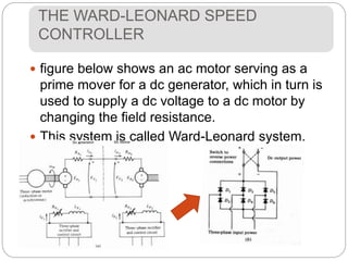
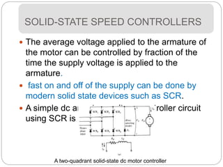
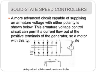
KL3073
DC Motors Starters and Breaking
Methods
DC MOTOR STARTERS
 In order for a dc motor to function
properly it must have some special
control and protection equipment
 The purposes of this equipment are.
To protect the motor against damage
 due to short circuits in the equipment
 from long-term overloads
 from excessive starting currents
 To provide a convenient manner in which
to control the operating speed of the
DC Motor Problems on Starting
 It must be protected from physical
damage during the starting period.
 At starting conditions, the motor is not
turning, and so EA = 0 V.
 The full-load current of this motor is:
 Since the internal resistance of a normal
dc motor is very low a very high current
flows.
 This current is over many times the
motor's rated full-load current. This may
Solution to the problem of excess current
 Insert a starting resistor in series with the
armature to limit the current flow.
 Resistor must not be in the circuit
permanently.
because of: excessive losses
• torque speed characteristic to
drop
 Resistor must be removed again as the
speed of the motor builds up.
Solution to the problem of excess current
 Shunt motor with an extra starting resistor.
 In designing the starter it is important to
properly pick the size and number of
resistor segments.
 Shuts the resistor bypass contacts at the
proper time
shunt motor with a
starting resistor
 Selected Rstart so that the current flow
equals say twice the rated current.
 the increasing EA decreases the IA in the
motor.
 When the IA falls to rated current, a
section of the starting resistor must be
taken out to increase the starting current
back up to 200 percent of rated current
 the increasing EA decreases the IA in the
motor.
 Repeat until all segments are out
Solution to the problem of excess current
How many steps are required to
accomplish the current limiting?
 Rtot as the original resistance in the
starting circuit
 The total resistance left in the starting
circuit after stages 1
 Initial starting resistance must be
 resistance R, must be switched out at 1st
stage
How many steps are required to
accomplish the current limiting?
 After switching that part of the resistance
out, the armature current must jump to
 Equating previous 2 equation
 By direct extension, the resistance left in
the circuit after the nth stage is switched
out is
How many steps are required to
accomplish the current limiting?
 At the boundary where RA = Rtot,n
 Equating previous 2 equation
 Solving for n yields
Example
 Example 6-7. Figure 6-24 shows a 100-hp 250-
V 350-A shunt de motor with an armature
resistance of 0.05 ohms. It is desired to design
a starter circuit for this motor which will limit the
maximum starting current to twice its rated
value and which will switch out sections of
resistance as the armature current falls to its
rated value.
 (a) How many stages of starting resistance will
be required to limit the current to the range
specified?
 (b) What must the value of each segment of the
DC Motor Starting Circuits
 Devices commonly used in motor-control
circuits
DC Motor Starting Circuits
 One common motor-starting circuit
DC Motor Starting Circuits
 One common motor-starting circuit
THE WARD-LEONARD SPEED
CONTROLLER
 The speed of a separately excited, shunt, or
compounded dc motor can be varied in one of
three ways:
 by changing the field resistance,
 changing the armature voltage, or
 changing the armature resistance.
THE WARD-LEONARD SPEED
CONTROLLER
 figure below shows an ac motor serving as a
prime mover for a dc generator, which in turn is
used to supply a dc voltage to a dc motor by
changing the field resistance.
 This system is called Ward-Leonard system.
THE WARD-LEONARD SPEED
CONTROLLER
 Controlling the field current of the dc generator
armature voltage can be controlled
 This allows the motor's speed to be smoothly
varied between a very small value and the base
speed.
 Higher speed can be achieved by reducing the
motor's field current
THE WARD-LEONARD SPEED
CONTROLLER
 if the field current of the generator is reversed,
polarity of generated voltage also reversed.
 This reverse the motor's direction of rotation.
 If the torque or the speed alone of the motor
reverses while the other quantity does not, then
the machine serves as a generator.
The operating range of a Ward-
Leonard motor-control system
SOLID-STATE SPEED CONTROLLERS
 The average voltage applied to the armature of
the motor can be controlled by fraction of the
time the supply voltage is applied to the
armature.
 fast on and off of the supply can be done by
modern solid state devices such as SCR.
 A simple dc armature voltage controller circuit
using SCR is shown below
A two-quadrant solid-state dc motor controller
SOLID-STATE SPEED CONTROLLERS
 A more advanced circuit capable of supplying
an armature voltage with either polarity is
shown below. This armature voltage control
circuit can permit a current flow out of the
positive terminals of the generator, so a motor
with this type of controller can regenerate
A 4-quadrant solid-state dc motor controller
DC MOTOR BREAKING METHODS
There are three kinds of electric breaking, namely:
 Rheostatic or dynamic breaking
 Plugging and
 Regenerative breaking
Electric breaking for shunt motors
 The armature of the shunt motor is disconnected
from the supply and it is connected across a
variable resistor R.
 The field winding is kept undisrupted and this
breaking is controlled by varying the series
resistor R.
 This method used generator action.
Rheostatic or dynamic breaking
Electric breaking for shunt motors
 the armature terminals are reversed to rotate the
motor in the reverse direction
 VT and the back Eb start acting in the same
direction.
Plugging or Reverse Breaking
Electric breaking for shunt motors
 In regenerative breaking, Eb is greater than Vt.
 The direction of IA and the armature torque Tb
are reversed
Regenerative Breaking
Electric breaking for series motors
 In this method the motor is disconnected from
supply. The field connection is reversed and the
motor is connected through a variable resistance
R.
Rheostatic or dynamic breaking
Electric breaking for series motors
 it is similar to that of shunt motor.
Plugging or Reverse Current Breaking

braking.ppt

  • 1.
    KL3073 DC Motors Startersand Breaking Methods
  • 2.
    DC MOTOR STARTERS In order for a dc motor to function properly it must have some special control and protection equipment  The purposes of this equipment are. To protect the motor against damage  due to short circuits in the equipment  from long-term overloads  from excessive starting currents  To provide a convenient manner in which to control the operating speed of the
  • 3.
    DC Motor Problemson Starting  It must be protected from physical damage during the starting period.  At starting conditions, the motor is not turning, and so EA = 0 V.  The full-load current of this motor is:  Since the internal resistance of a normal dc motor is very low a very high current flows.  This current is over many times the motor's rated full-load current. This may
  • 4.
    Solution to theproblem of excess current  Insert a starting resistor in series with the armature to limit the current flow.  Resistor must not be in the circuit permanently. because of: excessive losses • torque speed characteristic to drop  Resistor must be removed again as the speed of the motor builds up.
  • 5.
    Solution to theproblem of excess current  Shunt motor with an extra starting resistor.  In designing the starter it is important to properly pick the size and number of resistor segments.  Shuts the resistor bypass contacts at the proper time shunt motor with a starting resistor
  • 6.
     Selected Rstartso that the current flow equals say twice the rated current.  the increasing EA decreases the IA in the motor.  When the IA falls to rated current, a section of the starting resistor must be taken out to increase the starting current back up to 200 percent of rated current  the increasing EA decreases the IA in the motor.  Repeat until all segments are out Solution to the problem of excess current
  • 7.
    How many stepsare required to accomplish the current limiting?  Rtot as the original resistance in the starting circuit  The total resistance left in the starting circuit after stages 1  Initial starting resistance must be  resistance R, must be switched out at 1st stage
  • 8.
    How many stepsare required to accomplish the current limiting?  After switching that part of the resistance out, the armature current must jump to  Equating previous 2 equation  By direct extension, the resistance left in the circuit after the nth stage is switched out is
  • 9.
    How many stepsare required to accomplish the current limiting?  At the boundary where RA = Rtot,n  Equating previous 2 equation  Solving for n yields
  • 10.
    Example  Example 6-7.Figure 6-24 shows a 100-hp 250- V 350-A shunt de motor with an armature resistance of 0.05 ohms. It is desired to design a starter circuit for this motor which will limit the maximum starting current to twice its rated value and which will switch out sections of resistance as the armature current falls to its rated value.  (a) How many stages of starting resistance will be required to limit the current to the range specified?  (b) What must the value of each segment of the
  • 11.
    DC Motor StartingCircuits  Devices commonly used in motor-control circuits
  • 12.
    DC Motor StartingCircuits  One common motor-starting circuit
  • 13.
    DC Motor StartingCircuits  One common motor-starting circuit
  • 14.
    THE WARD-LEONARD SPEED CONTROLLER The speed of a separately excited, shunt, or compounded dc motor can be varied in one of three ways:  by changing the field resistance,  changing the armature voltage, or  changing the armature resistance.
  • 15.
    THE WARD-LEONARD SPEED CONTROLLER figure below shows an ac motor serving as a prime mover for a dc generator, which in turn is used to supply a dc voltage to a dc motor by changing the field resistance.  This system is called Ward-Leonard system.
  • 16.
    THE WARD-LEONARD SPEED CONTROLLER Controlling the field current of the dc generator armature voltage can be controlled  This allows the motor's speed to be smoothly varied between a very small value and the base speed.  Higher speed can be achieved by reducing the motor's field current
  • 17.
    THE WARD-LEONARD SPEED CONTROLLER if the field current of the generator is reversed, polarity of generated voltage also reversed.  This reverse the motor's direction of rotation.  If the torque or the speed alone of the motor reverses while the other quantity does not, then the machine serves as a generator. The operating range of a Ward- Leonard motor-control system
  • 18.
    SOLID-STATE SPEED CONTROLLERS The average voltage applied to the armature of the motor can be controlled by fraction of the time the supply voltage is applied to the armature.  fast on and off of the supply can be done by modern solid state devices such as SCR.  A simple dc armature voltage controller circuit using SCR is shown below A two-quadrant solid-state dc motor controller
  • 19.
    SOLID-STATE SPEED CONTROLLERS A more advanced circuit capable of supplying an armature voltage with either polarity is shown below. This armature voltage control circuit can permit a current flow out of the positive terminals of the generator, so a motor with this type of controller can regenerate A 4-quadrant solid-state dc motor controller
  • 20.
    DC MOTOR BREAKINGMETHODS There are three kinds of electric breaking, namely:  Rheostatic or dynamic breaking  Plugging and  Regenerative breaking
  • 21.
    Electric breaking forshunt motors  The armature of the shunt motor is disconnected from the supply and it is connected across a variable resistor R.  The field winding is kept undisrupted and this breaking is controlled by varying the series resistor R.  This method used generator action. Rheostatic or dynamic breaking
  • 22.
    Electric breaking forshunt motors  the armature terminals are reversed to rotate the motor in the reverse direction  VT and the back Eb start acting in the same direction. Plugging or Reverse Breaking
  • 23.
    Electric breaking forshunt motors  In regenerative breaking, Eb is greater than Vt.  The direction of IA and the armature torque Tb are reversed Regenerative Breaking
  • 24.
    Electric breaking forseries motors  In this method the motor is disconnected from supply. The field connection is reversed and the motor is connected through a variable resistance R. Rheostatic or dynamic breaking
  • 25.
    Electric breaking forseries motors  it is similar to that of shunt motor. Plugging or Reverse Current Breaking