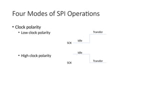
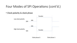
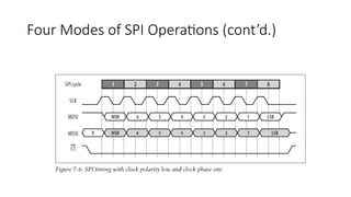
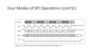
Serial Peripheral Interface
•SPI was developed by Motorola in 1980
• Synchronous serial protocol
• The master (CPU) and the slave (peripheral) are synchronized with a clock generated by
the master.
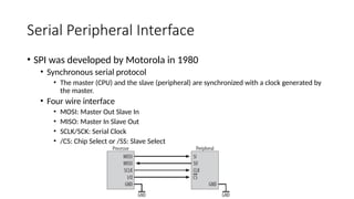
• Four wire interface
• MOSI: Master Out Slave In
• MISO: Master In Slave Out
• SCLK/SCK: Serial Clock
• /CS: Chip Select or /SS: Slave Select
5.
Serial Peripheral Interface(cont’d.)
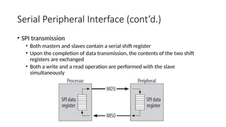
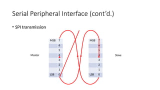
• SPI transmission
• Both masters and slaves contain a serial shift register
• Upon the completion of data transmission, the contents of the two shift
registers are exchanged
• Both a write and a read operation are performed with the slave
simultaneously
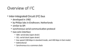
Overview of I2
C
•Inter-Integrated Circuit (I2
C) bus
• developed in 1982
• by Philips labs in Eindhoven, Netherlands
• similar to SPI
• synchronous serial communication protocol
• two-wire interface
• SDA: serial data (open drain)
• SCL: serial clock (open drain)
• low speed (100 kbps in standard mode, and 400 kbps in fast mode)
• bidirectional
• Synchronous to a common clock
15.
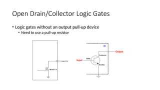
Open Drain/Collector LogicGates
• Logic gates without an output pull-up device
• Need to use a pull-up resistor
16.
Overview of I2
C
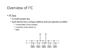
•I2
C bus
• A multi-master bus
• Each device has a unique address and can operate as either
• a transmitter (a bus master),
• a receiver (a bus slave), or
• both
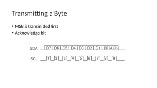
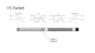
Transmitting a Bit
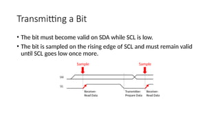
•The bit must become valid on SDA while SCL is low.
• The bit is sampled on the rising edge of SCL and must remain valid
until SCL goes low once more.
Sample Sample
Transmitter:
Prepare Data
Receiver:
Read Data
Receiver:
Read Data
20.
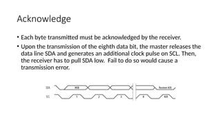
Acknowledge
• Each bytetransmitted must be acknowledged by the receiver.
• Upon the transmission of the eighth data bit, the master releases the
data line SDA and generates an additional clock pulse on SCL. Then,
the receiver has to pull SDA low. Fail to do so would cause a
transmission error.
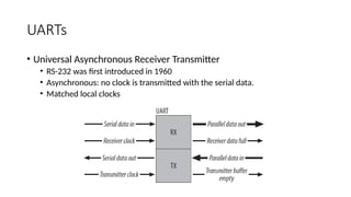
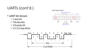
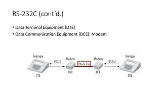
UARTs
• Universal AsynchronousReceiver Transmitter
• RS-232 was first introduced in 1960
• Asynchronous: no clock is transmitted with the serial data.
• Matched local clocks
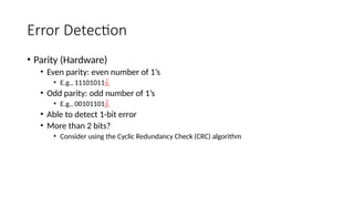
Error Detection
• Parity(Hardware)
• Even parity: even number of 1’s
• E.g., 11101011
• Odd parity: odd number of 1’s
• E.g., 00101101
• Able to detect 1-bit error
• More than 2 bits?
• Consider using the Cyclic Redundancy Check (CRC) algorithm
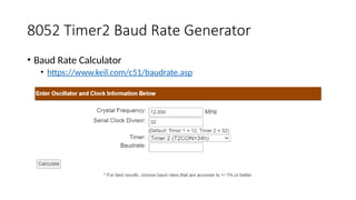
34.
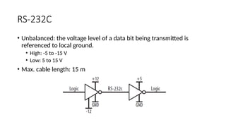
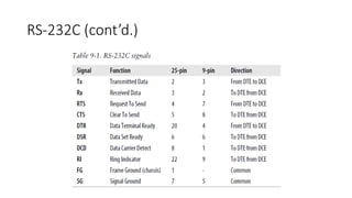
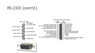
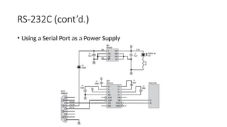
RS-232C
• Unbalanced: thevoltage level of a data bit being transmitted is
referenced to local ground.
• High: -5 to -15 V
• Low: 5 to 15 V
• Max. cable length: 15 m
![Interrupt Service Routine
• Interrupt number and register bank
In main program, SBUF = obuf[0]; oidx = 1;
void timer0_isr(void) __interrupt (4) __using(3)
{
if (TI) {
…
SBUF = obuf[o_idx++];
} else if (RI) {
ibuf[i_idx++] = SBUF;
…
}
}](https://image.slidesharecdn.com/serialcomminterface1-250913035853-3600eded/85/SerialCommInterface-47-320.jpg)


![Communication_Protocols[2][1].pptx on protocoals](https://cdn.slidesharecdn.com/ss_thumbnails/communicationprotocols21-250429164707-38355411-thumbnail.jpg?width=640&height=640&fit=bounds)