Downloaded 47 times


![Jan. 28, 2015 NIT-Patna: Foundation Day 2015 16
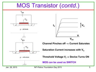
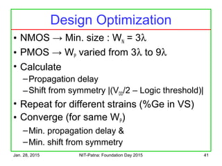
CMOS Design Example
Consider the Function
f = A . (B + C)
Design the
Pull Down
Network first
A
B C
PullUp
F
B
A
C
f = [A . (B + C)] is true
The Pull Down Network connects
‘f ’ to ground when
Connect Ground](https://image.slidesharecdn.com/trendsincmosdigitaldesign-150128003015-conversion-gate02/85/Trends-in-cmos-digital-design-16-320.jpg)


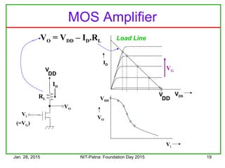


![Jan. 28, 2015 NIT-Patna: Foundation Day 2015 26
Vi VO
VO
Vi
VDD
VDD
VDS
ID
VDD
Tuning the Characteristics
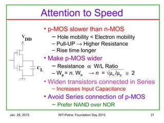
• Make the n-MOS wider
• It conducts more current
ID = ½ µCox[VGS – Vt]2
(W/L)
•Best Noise Margin
•When Vi = Voat VDD/2
•Wp = 3.Wn](https://image.slidesharecdn.com/trendsincmosdigitaldesign-150128003015-conversion-gate02/85/Trends-in-cmos-digital-design-25-320.jpg)


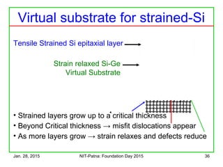

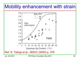
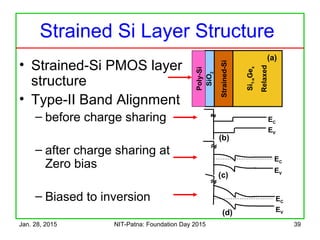
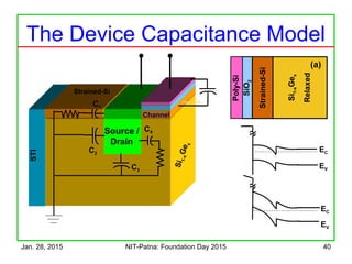

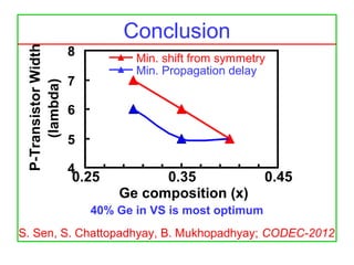

The document discusses the design and characteristics of CMOS digital circuits, specifically focusing on the operation of MOS transistors and their uses in logic circuits. It covers the functioning of n-MOS and p-MOS devices, logic design principles, noise margins, speed considerations, and the impact of strained silicon on mobility. Additionally, the document presents optimization strategies for semiconductor parameters to enhance performance in digital logic applications.