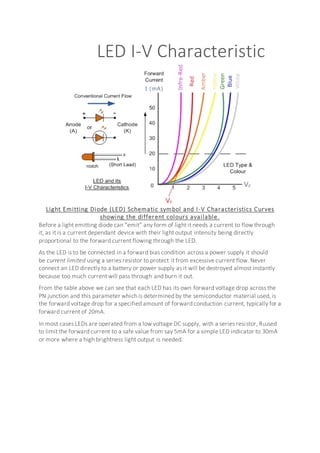
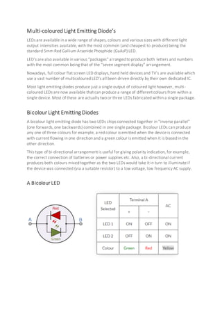
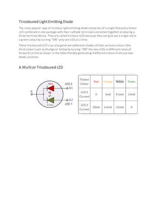
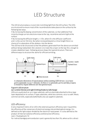
SlideShare a Scribd company logo
PHYSICS INVESTIGATORY PROJECT
LIGHT EMITTINGDIODE (LED)
Roll No: - Class: - 12th
Submitted By: Submitted To:-
Certificate
This is to certify that ankit of class 12th
has completed
her project in the subject of Physics as required
according to the syllabus as prescribed by the central
board of secondary education(CBSE)for the academic
session 2017-2018.
---------------------------
Signature
Acknowledgement
I would like to express my special thanks of gratitude to my teacher Mr. RAM
Sir as well as our principal Mr. Anil SIRwho gave me the golden opportunity to
do this wonderfulprojecton the topic Light Emitting Diode(LED), which also
helped me in doing a lot of Research and I came to know about so many new
things I am really thankful to them.
Secondly, I would also like to thank my parents and friends who helped me a
lot in finalizing this projectwithin the limited time frame.
I am making this project not only for marks butto also increase my knowledge.
Contents
S.No. Topics
1 Introduction
2 Types of LED’s
3 Working of LED
4 LED I-V Characteristic
5 Multicoloured LED’s
6 LED Structure
7 Advantages of LED’s
8 Disadvantages of LED’s
9 Applications of LED’s
10 Bibliography
Introduction
A light-emitting diode (LED) is a semiconductor device that emits
visible light when an electric current passes through it. The light is not
particularly bright, but in most LEDs it is monochromatic, occurring at
a single wavelength. The output from an LED can range from red (at a
wavelength of approximately 700 nanometers) to blue-violet (about
400 nanometers). Some LEDs emit infrared (IR) energy (830
nanometers or longer); such a device is known as an infrared-emitting
diode (IRED).
An LED or IRED consists of two elements of processed material
called P-type semiconductors and N-type semiconductors. These two
elements are placed in direct contact, forming a region called the P-N
junction. In this respect, the LED or IRED resembles most
other diode types, but there are important differences. The LED or
IRED has a transparent package, allowing visible or IR energy to pass
through. Also, the LED or IRED has a large PN-junction area whose
shape is tailored to the application.
Benefits of LEDs and IREDs, compared with incandescent and
fluorescent illuminating devices, include:
Low power requirement: Most types can be operated with battery
power supplies.
High efficiency: Most of the power supplied to an LED or IRED is
converted into radiation in the desired form, with minimal heat
production.
Long life: When properly installed, an LED or IRED can function for
decades.
Types of LED’s
 Gallium Arsenide (GaAs) – infra-red
 Gallium Arsenide Phosphide (GaAsP) – red to infra-red, orange
 Aluminium Gallium Arsenide Phosphide (AlGaAsP) – high-brightness red,
orange-red, orange, and yellow
 Gallium Phosphide (GaP) – red, yellow and green
 Aluminium Gallium Phosphide (AlGaP) – green
 Gallium Nitride (GaN) – green, emerald green
 Gallium Indium Nitride (GaInN) – near ultraviolet, bluish-green and blue
 Silicon Carbide (SiC) – blue as a substrate
 Zinc Selenide (ZnSe) – blue
 Aluminium Gallium Nitride (AlGaN) – ultraviolet
Working Of LED
A Light emitting diode (LED) is essentially a pn junction diode. When carriers are
injected across a forward-biased junction, it emits incoherent light. Most of the
commercial LEDs are realized using a highly doped n and a p Junction.
Figure1: p-n+ Junction under Unbiased and biased conditions.
(pn Junction Devices and Light Emitting Diodes by Safa Kasap)
To understand the principle, let’s consider an unbiased pn+ junction (Figure1 shows the
pn+ energy band diagram). The depletion region extends mainly into the p-side. There is
a potential barrier from Ec on the n-side to the Ec on the p-side, called the built-in voltage,
V0. This potential barrier prevents the excess free electrons on the n+ side from diffusing
into the p side.
When a Voltage V is applied across the junction, the built-in potential is reduced from V0
to V0 – V. This allows the electrons from the n+ side to get injected into the p-side. Since
electrons are the minority carriers in the p-side, this process is called minority carrier
injection. But the hole injection from the p side to n+ side is very less and so the current
is primarily due to the flow of electrons into the p-side.
These electrons injected into the p-side recombine with the holes. This recombination
results in spontaneous emission of photons (light). This effect is called injection
electroluminescence. These photons should be allowed to escape from the device without
being reabsorbed.
The recombination can be classified into the following two kinds
• Direct recombination
• Indirect recombination
Direct Recombination:
In direct band gap materials, the minimum energy of the conduction band lies directly
above the maximum energy of the valence band in momentum space energy (Figure 2
shows the E-k plot of a direct band gap material). In this material, free
electrons at the bottom of the conduction band can recombine directly with free holes at
the top of the valence band, as the momentum of the two particles is the same. This
transition from conduction band to valence band involves photon emission (takes care of
the principle of energy conservation). This is known as direct recombination. Direct
recombination occurs spontaneously. GaAs is an example of a direct band-gap
material.
Figure2: Direct Bandgap and Direct Recombination
Indirect Recombination:
In the indirect band gap materials, the minimum energy in the conduction band is shifted
by a k-vector relative to the valence band. The k-vector difference represents a difference
in momentum. Due to this difference in momentum, the probability of direct electronhole
recombination is less.
In these materials, additional dopants(impurities) are added which form very shallow
donor states. These donor states capture the free electrons locally; provides the necessary
momentum shift for recombination. These donor states serve as the recombination
centers. This is called Indirect (non-radiative) Recombination.
Figure3 shows the E-k plot of an indirect band gap material and an example of how
Nitrogen serves as a recombination center in GaAsP. In this case it creates a donor state,
when SiC is doped with Al, it recombination takes place through an acceptor level.
The indirect recombination should satisfy both conservation energy, and momentum.
Thus besides a photon emission, phonon emission or absorption has to take
place.
GaP is an example of an indirect band-gap material.
Figure3: Indirect Bandgap and NonRadiative recombination
The wavelength of the light emitted, and hence the color, depends on the band gap energy
of the materials forming the p-n junction.
The emitted photon energy is approximately equal to the band gap energy of the
semiconductor. The following equation relates the wavelength and the energy band gap.
hν = Eg
hc/λ = Eg
λ = hc/ Eg
Where h is Plank’s constant, c is the speed of the light and Eg is the energy band gap
Thus, a semiconductor with a 2 eV band-gap emits light at about 620 nm, in the red. A 3
eV band-gap material would emit at 414 nm, in the violet.
LED I-V Characteristic
Light Emitting Diode (LED) Schematic symbol and I-V Characteristics Curves
showing the different colours available.
Before a light emitting diode can “emit” any form of light it needs a current to flow through
it, as it is a current dependant device with their light output intensity being directly
proportional to the forward current flowing through the LED.
As the LED is to be connected in a forward bias condition across a power supply it should
be current limited using a series resistor to protect it from excessive current flow. Never
connect an LED directly to a battery or power supply as it will be destroyed almost instantly
because too much current will pass through and burn it out.
From the table above we can see that each LED has its own forward voltage drop across the
PN junction and this parameter which is determined by the semiconductor material used, is
the forward voltage drop for a specified amount of forward conduction current, typically for a
forward current of 20mA.
In most cases LEDs are operated from a low voltage DC supply, with a series resistor, RSused
to limit the forward current to a safe value from say 5mA for a simple LED indicator to 30mA
or more where a high brightness light output is needed.
Multi-coloured Light Emitting Diode’s
LEDs are available in a wide range of shapes, colours and various sizes with different light
output intensities available, with the most common (and cheapest to produce) being the
standard 5mm Red Gallium Arsenide Phosphide (GaAsP) LED.
LED’s are also available in various “packages” arranged to produce both letters and numbers
with the most common being that of the “seven segment display” arrangement.
Nowadays, full colour flat screen LED displays, hand held devices and TV’s are available which
use a vast number of multicoloured LED’s all been driven directly by their own dedicated IC.
Most light emitting diodes produce just a single output of coloured light however, multi-
coloured LEDs are now available that can produce a range of different colours from within a
single device. Most of these are actually two or three LEDs fabricated within a single package.
Bicolour Light Emitting Diodes
A bicolour light emitting diode has two LEDs chips connected together in “inverse parallel”
(one forwards, one backwards) combined in one single package. Bicolour LEDs can produce
any one of three colours for example, a red colour is emitted when the device is connected
with current flowing in one direction and a green colour is emitted when it is biased in the
other direction.
This type of bi-directional arrangement is useful for giving polarity indication, for example,
the correct connection of batteries or power supplies etc. Also, a bi-directional current
produces both colours mixed together as the two LEDs would take it in turn to illuminate if
the device was connected (via a suitable resistor) to a low voltage, low frequency AC supply.
A Bicolour LED
Tricoloured LightEmitting Diode
The most popular type of tricolour light emitting diode comprises of a single Red and a Green
LED combined in one package with their cathode terminals connected together producing a
three terminal device. They are called tricolour LEDs because they can give out a single red or
a green colour by turning “ON” only one LED at a time.
These tricoloured LED’s can also generate additional shades of their primary colours (the
third colour) such as Orange or Yellow by turning “ON” the two LEDs in different ratios of
forward current as shown in the table thereby generating 4 different colours from just two
diode junctions.
A Multi or Tricoloured LED
LED Structure
The LED structure plays a crucial role in emitting light from the LED surface. The LEDs
are structured to ensure most of the recombinations takes place on the surface by the
following two ways.
• By increasing the doping concentration of the substrate, so that additional free
minority charge carriers electrons move to the top, recombine and emit light at the
surface.
• By increasing the diffusion length L = √ Dτ, where D is the diffusion coefficient
and τ is the carrier life time. But when increased beyond a critical length there is a
chance of re-absorption of the photons into the device.
The LED has to be structured so that the photons generated from the device are emitted
without being reabsorbed. One solution is to make the p layer on the top thin, enough to
create a depletion layer. Following picture shows the layered structure. There are
different ways to structure the dome for efficient emitting.
Figure4: LEDstructure
(pn Junction Devices and Light Emitting Diodes by Safa Kasap)
LEDs are usually built on an n-type substrate, with an electrode attached to the p-type
layer deposited on its surface. P-type substrates, while less common, occur as well. Many
commercial LEDs, especially GaN/InGaN, also use sapphire substrate.
LED efficiency:
A very important metric of an LED is the external quantum efficiency ηext. It quantifies
the efficeincy of the conversion of electrical energy into emitted optical energy. It is
defined as the light output divided by the electrical input power. It is also defined as the
product of Internal radiative efficiency and Extraction efficiency.
ηext = Pout(optical) / IV
For indirect bandgap semiconductors ηext is generally less than 1%, where as for a direct
band gap material it could be substantial.
ηint = rate of radiation recombination/ Total recombination
The internal efficiency is a function of the quality of the material and the structure and
composition of the layer.
Advantages of LED’s
• LEDs produce more light per watt than incandescent bulbs; this is useful in
battery powered or energy-saving devices.
• LEDs can emit light of an intended color without the use of color filters that
traditional lighting methods require. This is more efficient and can lower initial
costs.
• The solid package of the LED can be designed to focus its light. Incandescent and
fluorescent sources often require an external reflector to collect light and direct it
in a usable manner.
• When used in applications where dimming is required, LEDs do not change their
color tint as the current passing through them is lowered, unlike incandescent
lamps, which turn yellow.
• LEDs are ideal for use in applications that are subject to frequent on-off cycling,
unlike fluorescent lamps that burn out more quickly when cycled frequently, or
High Intensity Discharge (HID) lamps that require a long time before restarting.
• LEDs, being solid state components, are difficult to damage with external shock.
Fluorescent and incandescent bulbs are easily broken if dropped on the ground.
• LEDs can have a relatively long useful life. A Philips LUXEON k2 LED has a
life time of about 50,000 hours, whereas Fluorescent tubes typically are rated at
about 30,000 hours, and incandescent light bulbs at 1,000–2,000 hours.
• LEDs mostly fail by dimming over time, rather than the abrupt burn-out of
incandescent bulbs.
• LEDs light up very quickly. A typical red indicator LED will achieve full
brightness in microseconds; Philips Lumileds technical datasheet DS23 for the
Luxeon Star states "less than 100ns." LEDs used in communications devices can
have even faster response times.
• LEDs can be very small and are easily populated onto printed circuit boards.
• LEDs do not contain mercury, unlike compact fluorescent lamps.
Disadvantages of using LED’s
• LEDs are currently more expensive, price per lumen, on an initial capital cost
basis, than more conventional lighting technologies. The additional expense
partially stems from the relatively low lumen output and the drive circuitry and
power supplies needed. However, when considering the total cost of ownership
(including energy and maintenance costs), LEDs far surpass incandescent or
halogen sources and begin to threaten the future existence of compact fluorescent
lamps.
• LED performance largely depends on the ambient temperature of the operating
environment. Over-driving the LED in high ambient temperatures may result in
overheating of the LED package, eventually leading to device failure. Adequate
heat-sinking is required to maintain long life.
• LEDs must be supplied with the correct current. This can involve series resistors
or current-regulated power supplies.
• LEDs do not approximate a "point source" of light, so they cannot be used in
applications needing a highly collimated beam. LEDs are not capable of providing
divergence below a few degrees. This is contrasted with commercial ruby lasers
with divergences of 0.2 degrees or less. However this can be corrected by using
lenses and other optical devices.
• There is increasing concern that blue LEDs and white LEDs are now capable of
exceeding safe limits of the so-called blue-light hazard as defined in the eye
safety specifications for example ANSI/IESNA RP-27.1-05: Recommended
Practice for Photobiological Safety for Lamp and Lamp Systems.
Applications of LED’s
 Indicator lights: These can be two-state (i.e., on/off), bar-graph, or alphabetic-numeric
readouts.
 LCD panel backlighting: Specialized white LEDs are used in flat-panel computer displays.
 Fiber opticdata transmission: Ease of modulation allows wide
communications bandwidth with minimal noise, resulting in high speed and accuracy.
 Remote control: Most home-entertainment "remotes" use IREDs to transmit data to the
main unit.
 Optoisolator: Stages in an electronic system can be connected together without
unwanted interaction.
Bibliography
The following books were used in completion of this project.
 NCERT Textbook of Physics for class 12th .
 Pradeep Fundamental of Physics for class 12th .
Also, the following websites were consulted for relevant materials.
 https://www.google.co.in/
 https://en.wikipedia.org
 http://www.electronics-tutorials.ws/diode/diode_8.html
 http://whatis.techtarget.com/definition/light-emitting-diode-LED

More Related Content

What's hot

LED-Light Emitting Diode
LED-Light Emitting DiodeLED-Light Emitting Diode
LED-Light Emitting Diode
Aon Ali Jaffery
 
Optoelectronics
OptoelectronicsOptoelectronics
Optoelectronics
DEPARTMENT OF PHYSICS
 
LED
LEDLED
light emmitting diode
light emmitting diodelight emmitting diode
light emmitting diode
salman01
 
Light-emitting diodes
Light-emitting diodes Light-emitting diodes
Light-emitting diodes
Yashpal Singh Katharria
 
LED (LIGHT EMITTING DIODE)
LED (LIGHT EMITTING DIODE)LED (LIGHT EMITTING DIODE)
LED (LIGHT EMITTING DIODE)
piyush yadav
 
LED
LEDLED
Technology Insight Report LeDs In Lighting
Technology Insight Report LeDs In LightingTechnology Insight Report LeDs In Lighting
Technology Insight Report LeDs In Lighting
Prashant Nair
 
Light Emitting Diode (LED)
Light Emitting Diode (LED)Light Emitting Diode (LED)
Light Emitting Diode (LED)
Javeria600
 
Led presentation
Led presentationLed presentation
Led presentation
AB Amit
 
Light emitting Diode
Light emitting DiodeLight emitting Diode
Light emitting Diode
SAurabh PRajapati
 
THE LIGHT EMITTING DIODE
THE LIGHT EMITTING DIODETHE LIGHT EMITTING DIODE
THE LIGHT EMITTING DIODE
Poojith Chowdhary
 
Light emitting diode’s a Basic Description of LED Bulbs...
Light emitting diode’s a Basic Description of LED Bulbs... Light emitting diode’s a Basic Description of LED Bulbs...
Light emitting diode’s a Basic Description of LED Bulbs...
Abhishek Jangid
 
Led 1
Led 1Led 1
Electroluminesccent polymer
Electroluminesccent polymerElectroluminesccent polymer
Electroluminesccent polymer
Omkar Rane
 
Optical presentation
Optical presentationOptical presentation
Optical presentation
Sujeet Kumar Jha
 
Light Emitting Diode Presentation Report
Light Emitting Diode  Presentation ReportLight Emitting Diode  Presentation Report
Light Emitting Diode Presentation Report
Devansh Gupta
 
Modulation of LED
Modulation of LEDModulation of LED
Modulation of LED
Priyanka Anni
 
Led ppt vgec ec engineering
Led ppt vgec ec engineeringLed ppt vgec ec engineering
Led ppt vgec ec engineering
Vijendrasingh Rathor
 
Spin Based LED and its applications in Daily life
Spin Based LED and its applications in Daily lifeSpin Based LED and its applications in Daily life
Spin Based LED and its applications in Daily life
OsamaMunawar1
 

What's hot (20)

LED-Light Emitting Diode
LED-Light Emitting DiodeLED-Light Emitting Diode
LED-Light Emitting Diode
 
Optoelectronics
OptoelectronicsOptoelectronics
Optoelectronics
 
LED
LEDLED
LED
 
light emmitting diode
light emmitting diodelight emmitting diode
light emmitting diode
 
Light-emitting diodes
Light-emitting diodes Light-emitting diodes
Light-emitting diodes
 
LED (LIGHT EMITTING DIODE)
LED (LIGHT EMITTING DIODE)LED (LIGHT EMITTING DIODE)
LED (LIGHT EMITTING DIODE)
 
LED
LEDLED
LED
 
Technology Insight Report LeDs In Lighting
Technology Insight Report LeDs In LightingTechnology Insight Report LeDs In Lighting
Technology Insight Report LeDs In Lighting
 
Light Emitting Diode (LED)
Light Emitting Diode (LED)Light Emitting Diode (LED)
Light Emitting Diode (LED)
 
Led presentation
Led presentationLed presentation
Led presentation
 
Light emitting Diode
Light emitting DiodeLight emitting Diode
Light emitting Diode
 
THE LIGHT EMITTING DIODE
THE LIGHT EMITTING DIODETHE LIGHT EMITTING DIODE
THE LIGHT EMITTING DIODE
 
Light emitting diode’s a Basic Description of LED Bulbs...
Light emitting diode’s a Basic Description of LED Bulbs... Light emitting diode’s a Basic Description of LED Bulbs...
Light emitting diode’s a Basic Description of LED Bulbs...
 
Led 1
Led 1Led 1
Led 1
 
Electroluminesccent polymer
Electroluminesccent polymerElectroluminesccent polymer
Electroluminesccent polymer
 
Optical presentation
Optical presentationOptical presentation
Optical presentation
 
Light Emitting Diode Presentation Report
Light Emitting Diode  Presentation ReportLight Emitting Diode  Presentation Report
Light Emitting Diode Presentation Report
 
Modulation of LED
Modulation of LEDModulation of LED
Modulation of LED
 
Led ppt vgec ec engineering
Led ppt vgec ec engineeringLed ppt vgec ec engineering
Led ppt vgec ec engineering
 
Spin Based LED and its applications in Daily life
Spin Based LED and its applications in Daily lifeSpin Based LED and its applications in Daily life
Spin Based LED and its applications in Daily life
 

Similar to Tejpratap

Semiconductors and LEDs
Semiconductors and LEDsSemiconductors and LEDs
Semiconductors and LEDs
Akash Ganguly
 
LED
LEDLED
OCN_Unit.3.pptx
OCN_Unit.3.pptxOCN_Unit.3.pptx
OCN_Unit.3.pptx
Dr.Prabu Mani
 
Diodes // LED // OLED
Diodes // LED // OLEDDiodes // LED // OLED
Diodes // LED // OLED
DheerendraKumar43
 
LED-light emitting diode
LED-light emitting diodeLED-light emitting diode
LED-light emitting diode
Bilawal Fiaz
 
Optical source LED by sufiyan a khan
Optical source LED by sufiyan a khanOptical source LED by sufiyan a khan
Optical source LED by sufiyan a khan
Sufiyan Khan
 
Semiconductor Physics Background and Light Emitting Diode(LEDs)-.pptx
Semiconductor Physics Background and Light Emitting Diode(LEDs)-.pptxSemiconductor Physics Background and Light Emitting Diode(LEDs)-.pptx
Semiconductor Physics Background and Light Emitting Diode(LEDs)-.pptx
bhoomijyani51
 
Types of Diodes Advantages and disadvantages, LE
Types of Diodes Advantages and disadvantages, LETypes of Diodes Advantages and disadvantages, LE
Types of Diodes Advantages and disadvantages, LE
Musab Hussain
 
special diode
special diodespecial diode
special diode
Asif Iqbal
 
EC 8751 - Optical Sources & Detectors
EC 8751 - Optical Sources & DetectorsEC 8751 - Optical Sources & Detectors
EC 8751 - Optical Sources & Detectors
MuthuvelArumugam4
 
Basic Electronics 1 by Dr. Mathivanan Velumani
Basic Electronics 1 by Dr. Mathivanan VelumaniBasic Electronics 1 by Dr. Mathivanan Velumani
Basic Electronics 1 by Dr. Mathivanan Velumani
Mathivanan Velumani
 
Communication Engineering LED and LASER Sources.ppt
Communication Engineering LED and LASER Sources.pptCommunication Engineering LED and LASER Sources.ppt
Communication Engineering LED and LASER Sources.ppt
MdYekraRahman1
 
KN_Sem2_LED LCD etc.pdf
KN_Sem2_LED LCD etc.pdfKN_Sem2_LED LCD etc.pdf
KN_Sem2_LED LCD etc.pdf
KrishanuNaskar1
 
Pin photodiode.pptx ashvani
Pin photodiode.pptx ashvaniPin photodiode.pptx ashvani
Pin photodiode.pptx ashvani
Ashvani Shukla
 
473 Lecture 17 - Electronic & Photonic Materials shortened.ppt
473 Lecture 17  - Electronic & Photonic Materials shortened.ppt473 Lecture 17  - Electronic & Photonic Materials shortened.ppt
473 Lecture 17 - Electronic & Photonic Materials shortened.ppt
OverloadedSense
 
photodiode
photodiodephotodiode
photodiode
Sahil Bansal
 
Introduction to Photoelectrochemical (PEC) Water Splitting
Introduction to Photoelectrochemical (PEC) Water SplittingIntroduction to Photoelectrochemical (PEC) Water Splitting
Introduction to Photoelectrochemical (PEC) Water Splitting
Anamika Banerjee
 
Special purpose Diodes
Special purpose DiodesSpecial purpose Diodes
Special purpose Diodes
Prerak Trivedi
 
Lecture 16
Lecture 16Lecture 16
Lecture 16
luyenkimnet
 
optical communication Unit 3
optical communication Unit 3optical communication Unit 3
optical communication Unit 3
Asif Iqbal
 

Similar to Tejpratap (20)

Semiconductors and LEDs
Semiconductors and LEDsSemiconductors and LEDs
Semiconductors and LEDs
 
LED
LEDLED
LED
 
OCN_Unit.3.pptx
OCN_Unit.3.pptxOCN_Unit.3.pptx
OCN_Unit.3.pptx
 
Diodes // LED // OLED
Diodes // LED // OLEDDiodes // LED // OLED
Diodes // LED // OLED
 
LED-light emitting diode
LED-light emitting diodeLED-light emitting diode
LED-light emitting diode
 
Optical source LED by sufiyan a khan
Optical source LED by sufiyan a khanOptical source LED by sufiyan a khan
Optical source LED by sufiyan a khan
 
Semiconductor Physics Background and Light Emitting Diode(LEDs)-.pptx
Semiconductor Physics Background and Light Emitting Diode(LEDs)-.pptxSemiconductor Physics Background and Light Emitting Diode(LEDs)-.pptx
Semiconductor Physics Background and Light Emitting Diode(LEDs)-.pptx
 
Types of Diodes Advantages and disadvantages, LE
Types of Diodes Advantages and disadvantages, LETypes of Diodes Advantages and disadvantages, LE
Types of Diodes Advantages and disadvantages, LE
 
special diode
special diodespecial diode
special diode
 
EC 8751 - Optical Sources & Detectors
EC 8751 - Optical Sources & DetectorsEC 8751 - Optical Sources & Detectors
EC 8751 - Optical Sources & Detectors
 
Basic Electronics 1 by Dr. Mathivanan Velumani
Basic Electronics 1 by Dr. Mathivanan VelumaniBasic Electronics 1 by Dr. Mathivanan Velumani
Basic Electronics 1 by Dr. Mathivanan Velumani
 
Communication Engineering LED and LASER Sources.ppt
Communication Engineering LED and LASER Sources.pptCommunication Engineering LED and LASER Sources.ppt
Communication Engineering LED and LASER Sources.ppt
 
KN_Sem2_LED LCD etc.pdf
KN_Sem2_LED LCD etc.pdfKN_Sem2_LED LCD etc.pdf
KN_Sem2_LED LCD etc.pdf
 
Pin photodiode.pptx ashvani
Pin photodiode.pptx ashvaniPin photodiode.pptx ashvani
Pin photodiode.pptx ashvani
 
473 Lecture 17 - Electronic & Photonic Materials shortened.ppt
473 Lecture 17  - Electronic & Photonic Materials shortened.ppt473 Lecture 17  - Electronic & Photonic Materials shortened.ppt
473 Lecture 17 - Electronic & Photonic Materials shortened.ppt
 
photodiode
photodiodephotodiode
photodiode
 
Introduction to Photoelectrochemical (PEC) Water Splitting
Introduction to Photoelectrochemical (PEC) Water SplittingIntroduction to Photoelectrochemical (PEC) Water Splitting
Introduction to Photoelectrochemical (PEC) Water Splitting
 
Special purpose Diodes
Special purpose DiodesSpecial purpose Diodes
Special purpose Diodes
 
Lecture 16
Lecture 16Lecture 16
Lecture 16
 
optical communication Unit 3
optical communication Unit 3optical communication Unit 3
optical communication Unit 3
 

Recently uploaded

Remote Sensing and Computational, Evolutionary, Supercomputing, and Intellige...
Remote Sensing and Computational, Evolutionary, Supercomputing, and Intellige...Remote Sensing and Computational, Evolutionary, Supercomputing, and Intellige...
Remote Sensing and Computational, Evolutionary, Supercomputing, and Intellige...
University of Maribor
 
Compexometric titration/Chelatorphy titration/chelating titration
Compexometric titration/Chelatorphy titration/chelating titrationCompexometric titration/Chelatorphy titration/chelating titration
Compexometric titration/Chelatorphy titration/chelating titration
Vandana Devesh Sharma
 
The use of Nauplii and metanauplii artemia in aquaculture (brine shrimp).pptx
The use of Nauplii and metanauplii artemia in aquaculture (brine shrimp).pptxThe use of Nauplii and metanauplii artemia in aquaculture (brine shrimp).pptx
The use of Nauplii and metanauplii artemia in aquaculture (brine shrimp).pptx
MAGOTI ERNEST
 
SAR of Medicinal Chemistry 1st by dk.pdf
SAR of Medicinal Chemistry 1st by dk.pdfSAR of Medicinal Chemistry 1st by dk.pdf
SAR of Medicinal Chemistry 1st by dk.pdf
KrushnaDarade1
 
Thornton ESPP slides UK WW Network 4_6_24.pdf
Thornton ESPP slides UK WW Network 4_6_24.pdfThornton ESPP slides UK WW Network 4_6_24.pdf
Thornton ESPP slides UK WW Network 4_6_24.pdf
European Sustainable Phosphorus Platform
 
EWOCS-I: The catalog of X-ray sources in Westerlund 1 from the Extended Weste...
EWOCS-I: The catalog of X-ray sources in Westerlund 1 from the Extended Weste...EWOCS-I: The catalog of X-ray sources in Westerlund 1 from the Extended Weste...
EWOCS-I: The catalog of X-ray sources in Westerlund 1 from the Extended Weste...
Sérgio Sacani
 
Applied Science: Thermodynamics, Laws & Methodology.pdf
Applied Science: Thermodynamics, Laws & Methodology.pdfApplied Science: Thermodynamics, Laws & Methodology.pdf
Applied Science: Thermodynamics, Laws & Methodology.pdf
University of Hertfordshire
 
Medical Orthopedic PowerPoint Templates.pptx
Medical Orthopedic PowerPoint Templates.pptxMedical Orthopedic PowerPoint Templates.pptx
Medical Orthopedic PowerPoint Templates.pptx
terusbelajar5
 
Shallowest Oil Discovery of Turkiye.pptx
Shallowest Oil Discovery of Turkiye.pptxShallowest Oil Discovery of Turkiye.pptx
Shallowest Oil Discovery of Turkiye.pptx
Gokturk Mehmet Dilci
 
Bob Reedy - Nitrate in Texas Groundwater.pdf
Bob Reedy - Nitrate in Texas Groundwater.pdfBob Reedy - Nitrate in Texas Groundwater.pdf
Bob Reedy - Nitrate in Texas Groundwater.pdf
Texas Alliance of Groundwater Districts
 
Randomised Optimisation Algorithms in DAPHNE
Randomised Optimisation Algorithms in DAPHNERandomised Optimisation Algorithms in DAPHNE
Randomised Optimisation Algorithms in DAPHNE
University of Maribor
 
GBSN - Biochemistry (Unit 6) Chemistry of Proteins
GBSN - Biochemistry (Unit 6) Chemistry of ProteinsGBSN - Biochemistry (Unit 6) Chemistry of Proteins
GBSN - Biochemistry (Unit 6) Chemistry of Proteins
Areesha Ahmad
 
ESR spectroscopy in liquid food and beverages.pptx
ESR spectroscopy in liquid food and beverages.pptxESR spectroscopy in liquid food and beverages.pptx
ESR spectroscopy in liquid food and beverages.pptx
PRIYANKA PATEL
 
Describing and Interpreting an Immersive Learning Case with the Immersion Cub...
Describing and Interpreting an Immersive Learning Case with the Immersion Cub...Describing and Interpreting an Immersive Learning Case with the Immersion Cub...
Describing and Interpreting an Immersive Learning Case with the Immersion Cub...
Leonel Morgado
 
Oedema_types_causes_pathophysiology.pptx
Oedema_types_causes_pathophysiology.pptxOedema_types_causes_pathophysiology.pptx
Oedema_types_causes_pathophysiology.pptx
muralinath2
 
The cost of acquiring information by natural selection
The cost of acquiring information by natural selectionThe cost of acquiring information by natural selection
The cost of acquiring information by natural selection
Carl Bergstrom
 
Authoring a personal GPT for your research and practice: How we created the Q...
Authoring a personal GPT for your research and practice: How we created the Q...Authoring a personal GPT for your research and practice: How we created the Q...
Authoring a personal GPT for your research and practice: How we created the Q...
Leonel Morgado
 
waterlessdyeingtechnolgyusing carbon dioxide chemicalspdf
waterlessdyeingtechnolgyusing carbon dioxide chemicalspdfwaterlessdyeingtechnolgyusing carbon dioxide chemicalspdf
waterlessdyeingtechnolgyusing carbon dioxide chemicalspdf
LengamoLAppostilic
 
Unlocking the mysteries of reproduction: Exploring fecundity and gonadosomati...
Unlocking the mysteries of reproduction: Exploring fecundity and gonadosomati...Unlocking the mysteries of reproduction: Exploring fecundity and gonadosomati...
Unlocking the mysteries of reproduction: Exploring fecundity and gonadosomati...
AbdullaAlAsif1
 
NuGOweek 2024 Ghent programme overview flyer
NuGOweek 2024 Ghent programme overview flyerNuGOweek 2024 Ghent programme overview flyer
NuGOweek 2024 Ghent programme overview flyer
pablovgd
 

Recently uploaded (20)

Remote Sensing and Computational, Evolutionary, Supercomputing, and Intellige...
Remote Sensing and Computational, Evolutionary, Supercomputing, and Intellige...Remote Sensing and Computational, Evolutionary, Supercomputing, and Intellige...
Remote Sensing and Computational, Evolutionary, Supercomputing, and Intellige...
 
Compexometric titration/Chelatorphy titration/chelating titration
Compexometric titration/Chelatorphy titration/chelating titrationCompexometric titration/Chelatorphy titration/chelating titration
Compexometric titration/Chelatorphy titration/chelating titration
 
The use of Nauplii and metanauplii artemia in aquaculture (brine shrimp).pptx
The use of Nauplii and metanauplii artemia in aquaculture (brine shrimp).pptxThe use of Nauplii and metanauplii artemia in aquaculture (brine shrimp).pptx
The use of Nauplii and metanauplii artemia in aquaculture (brine shrimp).pptx
 
SAR of Medicinal Chemistry 1st by dk.pdf
SAR of Medicinal Chemistry 1st by dk.pdfSAR of Medicinal Chemistry 1st by dk.pdf
SAR of Medicinal Chemistry 1st by dk.pdf
 
Thornton ESPP slides UK WW Network 4_6_24.pdf
Thornton ESPP slides UK WW Network 4_6_24.pdfThornton ESPP slides UK WW Network 4_6_24.pdf
Thornton ESPP slides UK WW Network 4_6_24.pdf
 
EWOCS-I: The catalog of X-ray sources in Westerlund 1 from the Extended Weste...
EWOCS-I: The catalog of X-ray sources in Westerlund 1 from the Extended Weste...EWOCS-I: The catalog of X-ray sources in Westerlund 1 from the Extended Weste...
EWOCS-I: The catalog of X-ray sources in Westerlund 1 from the Extended Weste...
 
Applied Science: Thermodynamics, Laws & Methodology.pdf
Applied Science: Thermodynamics, Laws & Methodology.pdfApplied Science: Thermodynamics, Laws & Methodology.pdf
Applied Science: Thermodynamics, Laws & Methodology.pdf
 
Medical Orthopedic PowerPoint Templates.pptx
Medical Orthopedic PowerPoint Templates.pptxMedical Orthopedic PowerPoint Templates.pptx
Medical Orthopedic PowerPoint Templates.pptx
 
Shallowest Oil Discovery of Turkiye.pptx
Shallowest Oil Discovery of Turkiye.pptxShallowest Oil Discovery of Turkiye.pptx
Shallowest Oil Discovery of Turkiye.pptx
 
Bob Reedy - Nitrate in Texas Groundwater.pdf
Bob Reedy - Nitrate in Texas Groundwater.pdfBob Reedy - Nitrate in Texas Groundwater.pdf
Bob Reedy - Nitrate in Texas Groundwater.pdf
 
Randomised Optimisation Algorithms in DAPHNE
Randomised Optimisation Algorithms in DAPHNERandomised Optimisation Algorithms in DAPHNE
Randomised Optimisation Algorithms in DAPHNE
 
GBSN - Biochemistry (Unit 6) Chemistry of Proteins
GBSN - Biochemistry (Unit 6) Chemistry of ProteinsGBSN - Biochemistry (Unit 6) Chemistry of Proteins
GBSN - Biochemistry (Unit 6) Chemistry of Proteins
 
ESR spectroscopy in liquid food and beverages.pptx
ESR spectroscopy in liquid food and beverages.pptxESR spectroscopy in liquid food and beverages.pptx
ESR spectroscopy in liquid food and beverages.pptx
 
Describing and Interpreting an Immersive Learning Case with the Immersion Cub...
Describing and Interpreting an Immersive Learning Case with the Immersion Cub...Describing and Interpreting an Immersive Learning Case with the Immersion Cub...
Describing and Interpreting an Immersive Learning Case with the Immersion Cub...
 
Oedema_types_causes_pathophysiology.pptx
Oedema_types_causes_pathophysiology.pptxOedema_types_causes_pathophysiology.pptx
Oedema_types_causes_pathophysiology.pptx
 
The cost of acquiring information by natural selection
The cost of acquiring information by natural selectionThe cost of acquiring information by natural selection
The cost of acquiring information by natural selection
 
Authoring a personal GPT for your research and practice: How we created the Q...
Authoring a personal GPT for your research and practice: How we created the Q...Authoring a personal GPT for your research and practice: How we created the Q...
Authoring a personal GPT for your research and practice: How we created the Q...
 
waterlessdyeingtechnolgyusing carbon dioxide chemicalspdf
waterlessdyeingtechnolgyusing carbon dioxide chemicalspdfwaterlessdyeingtechnolgyusing carbon dioxide chemicalspdf
waterlessdyeingtechnolgyusing carbon dioxide chemicalspdf
 
Unlocking the mysteries of reproduction: Exploring fecundity and gonadosomati...
Unlocking the mysteries of reproduction: Exploring fecundity and gonadosomati...Unlocking the mysteries of reproduction: Exploring fecundity and gonadosomati...
Unlocking the mysteries of reproduction: Exploring fecundity and gonadosomati...
 
NuGOweek 2024 Ghent programme overview flyer
NuGOweek 2024 Ghent programme overview flyerNuGOweek 2024 Ghent programme overview flyer
NuGOweek 2024 Ghent programme overview flyer
 

Tejpratap

  • 1. PHYSICS INVESTIGATORY PROJECT LIGHT EMITTINGDIODE (LED) Roll No: - Class: - 12th Submitted By: Submitted To:-
  • 2. Certificate This is to certify that ankit of class 12th has completed her project in the subject of Physics as required according to the syllabus as prescribed by the central board of secondary education(CBSE)for the academic session 2017-2018. --------------------------- Signature
  • 3. Acknowledgement I would like to express my special thanks of gratitude to my teacher Mr. RAM Sir as well as our principal Mr. Anil SIRwho gave me the golden opportunity to do this wonderfulprojecton the topic Light Emitting Diode(LED), which also helped me in doing a lot of Research and I came to know about so many new things I am really thankful to them. Secondly, I would also like to thank my parents and friends who helped me a lot in finalizing this projectwithin the limited time frame. I am making this project not only for marks butto also increase my knowledge.
  • 4. Contents S.No. Topics 1 Introduction 2 Types of LED’s 3 Working of LED 4 LED I-V Characteristic 5 Multicoloured LED’s 6 LED Structure 7 Advantages of LED’s 8 Disadvantages of LED’s 9 Applications of LED’s 10 Bibliography
  • 5. Introduction A light-emitting diode (LED) is a semiconductor device that emits visible light when an electric current passes through it. The light is not particularly bright, but in most LEDs it is monochromatic, occurring at a single wavelength. The output from an LED can range from red (at a wavelength of approximately 700 nanometers) to blue-violet (about 400 nanometers). Some LEDs emit infrared (IR) energy (830 nanometers or longer); such a device is known as an infrared-emitting diode (IRED). An LED or IRED consists of two elements of processed material called P-type semiconductors and N-type semiconductors. These two elements are placed in direct contact, forming a region called the P-N junction. In this respect, the LED or IRED resembles most other diode types, but there are important differences. The LED or IRED has a transparent package, allowing visible or IR energy to pass through. Also, the LED or IRED has a large PN-junction area whose shape is tailored to the application. Benefits of LEDs and IREDs, compared with incandescent and fluorescent illuminating devices, include: Low power requirement: Most types can be operated with battery power supplies. High efficiency: Most of the power supplied to an LED or IRED is converted into radiation in the desired form, with minimal heat production. Long life: When properly installed, an LED or IRED can function for decades.
  • 6. Types of LED’s  Gallium Arsenide (GaAs) – infra-red  Gallium Arsenide Phosphide (GaAsP) – red to infra-red, orange  Aluminium Gallium Arsenide Phosphide (AlGaAsP) – high-brightness red, orange-red, orange, and yellow  Gallium Phosphide (GaP) – red, yellow and green  Aluminium Gallium Phosphide (AlGaP) – green  Gallium Nitride (GaN) – green, emerald green  Gallium Indium Nitride (GaInN) – near ultraviolet, bluish-green and blue  Silicon Carbide (SiC) – blue as a substrate  Zinc Selenide (ZnSe) – blue  Aluminium Gallium Nitride (AlGaN) – ultraviolet
  • 7. Working Of LED A Light emitting diode (LED) is essentially a pn junction diode. When carriers are injected across a forward-biased junction, it emits incoherent light. Most of the commercial LEDs are realized using a highly doped n and a p Junction. Figure1: p-n+ Junction under Unbiased and biased conditions. (pn Junction Devices and Light Emitting Diodes by Safa Kasap) To understand the principle, let’s consider an unbiased pn+ junction (Figure1 shows the pn+ energy band diagram). The depletion region extends mainly into the p-side. There is a potential barrier from Ec on the n-side to the Ec on the p-side, called the built-in voltage, V0. This potential barrier prevents the excess free electrons on the n+ side from diffusing into the p side. When a Voltage V is applied across the junction, the built-in potential is reduced from V0 to V0 – V. This allows the electrons from the n+ side to get injected into the p-side. Since electrons are the minority carriers in the p-side, this process is called minority carrier injection. But the hole injection from the p side to n+ side is very less and so the current is primarily due to the flow of electrons into the p-side. These electrons injected into the p-side recombine with the holes. This recombination results in spontaneous emission of photons (light). This effect is called injection electroluminescence. These photons should be allowed to escape from the device without being reabsorbed. The recombination can be classified into the following two kinds • Direct recombination
  • 8. • Indirect recombination Direct Recombination: In direct band gap materials, the minimum energy of the conduction band lies directly above the maximum energy of the valence band in momentum space energy (Figure 2 shows the E-k plot of a direct band gap material). In this material, free electrons at the bottom of the conduction band can recombine directly with free holes at the top of the valence band, as the momentum of the two particles is the same. This transition from conduction band to valence band involves photon emission (takes care of the principle of energy conservation). This is known as direct recombination. Direct recombination occurs spontaneously. GaAs is an example of a direct band-gap material. Figure2: Direct Bandgap and Direct Recombination Indirect Recombination: In the indirect band gap materials, the minimum energy in the conduction band is shifted by a k-vector relative to the valence band. The k-vector difference represents a difference in momentum. Due to this difference in momentum, the probability of direct electronhole recombination is less. In these materials, additional dopants(impurities) are added which form very shallow donor states. These donor states capture the free electrons locally; provides the necessary momentum shift for recombination. These donor states serve as the recombination centers. This is called Indirect (non-radiative) Recombination. Figure3 shows the E-k plot of an indirect band gap material and an example of how Nitrogen serves as a recombination center in GaAsP. In this case it creates a donor state, when SiC is doped with Al, it recombination takes place through an acceptor level. The indirect recombination should satisfy both conservation energy, and momentum. Thus besides a photon emission, phonon emission or absorption has to take place. GaP is an example of an indirect band-gap material.
  • 9. Figure3: Indirect Bandgap and NonRadiative recombination The wavelength of the light emitted, and hence the color, depends on the band gap energy of the materials forming the p-n junction. The emitted photon energy is approximately equal to the band gap energy of the semiconductor. The following equation relates the wavelength and the energy band gap. hν = Eg hc/λ = Eg λ = hc/ Eg Where h is Plank’s constant, c is the speed of the light and Eg is the energy band gap Thus, a semiconductor with a 2 eV band-gap emits light at about 620 nm, in the red. A 3 eV band-gap material would emit at 414 nm, in the violet.
  • 10. LED I-V Characteristic Light Emitting Diode (LED) Schematic symbol and I-V Characteristics Curves showing the different colours available. Before a light emitting diode can “emit” any form of light it needs a current to flow through it, as it is a current dependant device with their light output intensity being directly proportional to the forward current flowing through the LED. As the LED is to be connected in a forward bias condition across a power supply it should be current limited using a series resistor to protect it from excessive current flow. Never connect an LED directly to a battery or power supply as it will be destroyed almost instantly because too much current will pass through and burn it out. From the table above we can see that each LED has its own forward voltage drop across the PN junction and this parameter which is determined by the semiconductor material used, is the forward voltage drop for a specified amount of forward conduction current, typically for a forward current of 20mA. In most cases LEDs are operated from a low voltage DC supply, with a series resistor, RSused to limit the forward current to a safe value from say 5mA for a simple LED indicator to 30mA or more where a high brightness light output is needed.
  • 11. Multi-coloured Light Emitting Diode’s LEDs are available in a wide range of shapes, colours and various sizes with different light output intensities available, with the most common (and cheapest to produce) being the standard 5mm Red Gallium Arsenide Phosphide (GaAsP) LED. LED’s are also available in various “packages” arranged to produce both letters and numbers with the most common being that of the “seven segment display” arrangement. Nowadays, full colour flat screen LED displays, hand held devices and TV’s are available which use a vast number of multicoloured LED’s all been driven directly by their own dedicated IC. Most light emitting diodes produce just a single output of coloured light however, multi- coloured LEDs are now available that can produce a range of different colours from within a single device. Most of these are actually two or three LEDs fabricated within a single package. Bicolour Light Emitting Diodes A bicolour light emitting diode has two LEDs chips connected together in “inverse parallel” (one forwards, one backwards) combined in one single package. Bicolour LEDs can produce any one of three colours for example, a red colour is emitted when the device is connected with current flowing in one direction and a green colour is emitted when it is biased in the other direction. This type of bi-directional arrangement is useful for giving polarity indication, for example, the correct connection of batteries or power supplies etc. Also, a bi-directional current produces both colours mixed together as the two LEDs would take it in turn to illuminate if the device was connected (via a suitable resistor) to a low voltage, low frequency AC supply. A Bicolour LED
  • 12. Tricoloured LightEmitting Diode The most popular type of tricolour light emitting diode comprises of a single Red and a Green LED combined in one package with their cathode terminals connected together producing a three terminal device. They are called tricolour LEDs because they can give out a single red or a green colour by turning “ON” only one LED at a time. These tricoloured LED’s can also generate additional shades of their primary colours (the third colour) such as Orange or Yellow by turning “ON” the two LEDs in different ratios of forward current as shown in the table thereby generating 4 different colours from just two diode junctions. A Multi or Tricoloured LED
  • 13. LED Structure The LED structure plays a crucial role in emitting light from the LED surface. The LEDs are structured to ensure most of the recombinations takes place on the surface by the following two ways. • By increasing the doping concentration of the substrate, so that additional free minority charge carriers electrons move to the top, recombine and emit light at the surface. • By increasing the diffusion length L = √ Dτ, where D is the diffusion coefficient and τ is the carrier life time. But when increased beyond a critical length there is a chance of re-absorption of the photons into the device. The LED has to be structured so that the photons generated from the device are emitted without being reabsorbed. One solution is to make the p layer on the top thin, enough to create a depletion layer. Following picture shows the layered structure. There are different ways to structure the dome for efficient emitting. Figure4: LEDstructure (pn Junction Devices and Light Emitting Diodes by Safa Kasap) LEDs are usually built on an n-type substrate, with an electrode attached to the p-type layer deposited on its surface. P-type substrates, while less common, occur as well. Many commercial LEDs, especially GaN/InGaN, also use sapphire substrate. LED efficiency: A very important metric of an LED is the external quantum efficiency ηext. It quantifies the efficeincy of the conversion of electrical energy into emitted optical energy. It is defined as the light output divided by the electrical input power. It is also defined as the product of Internal radiative efficiency and Extraction efficiency. ηext = Pout(optical) / IV For indirect bandgap semiconductors ηext is generally less than 1%, where as for a direct
  • 14. band gap material it could be substantial. ηint = rate of radiation recombination/ Total recombination The internal efficiency is a function of the quality of the material and the structure and composition of the layer.
  • 15. Advantages of LED’s • LEDs produce more light per watt than incandescent bulbs; this is useful in battery powered or energy-saving devices. • LEDs can emit light of an intended color without the use of color filters that traditional lighting methods require. This is more efficient and can lower initial costs. • The solid package of the LED can be designed to focus its light. Incandescent and fluorescent sources often require an external reflector to collect light and direct it in a usable manner. • When used in applications where dimming is required, LEDs do not change their color tint as the current passing through them is lowered, unlike incandescent lamps, which turn yellow. • LEDs are ideal for use in applications that are subject to frequent on-off cycling, unlike fluorescent lamps that burn out more quickly when cycled frequently, or High Intensity Discharge (HID) lamps that require a long time before restarting. • LEDs, being solid state components, are difficult to damage with external shock. Fluorescent and incandescent bulbs are easily broken if dropped on the ground. • LEDs can have a relatively long useful life. A Philips LUXEON k2 LED has a life time of about 50,000 hours, whereas Fluorescent tubes typically are rated at about 30,000 hours, and incandescent light bulbs at 1,000–2,000 hours. • LEDs mostly fail by dimming over time, rather than the abrupt burn-out of incandescent bulbs. • LEDs light up very quickly. A typical red indicator LED will achieve full brightness in microseconds; Philips Lumileds technical datasheet DS23 for the Luxeon Star states "less than 100ns." LEDs used in communications devices can have even faster response times. • LEDs can be very small and are easily populated onto printed circuit boards. • LEDs do not contain mercury, unlike compact fluorescent lamps.
  • 16. Disadvantages of using LED’s • LEDs are currently more expensive, price per lumen, on an initial capital cost basis, than more conventional lighting technologies. The additional expense partially stems from the relatively low lumen output and the drive circuitry and power supplies needed. However, when considering the total cost of ownership (including energy and maintenance costs), LEDs far surpass incandescent or halogen sources and begin to threaten the future existence of compact fluorescent lamps. • LED performance largely depends on the ambient temperature of the operating environment. Over-driving the LED in high ambient temperatures may result in overheating of the LED package, eventually leading to device failure. Adequate heat-sinking is required to maintain long life. • LEDs must be supplied with the correct current. This can involve series resistors or current-regulated power supplies. • LEDs do not approximate a "point source" of light, so they cannot be used in applications needing a highly collimated beam. LEDs are not capable of providing divergence below a few degrees. This is contrasted with commercial ruby lasers with divergences of 0.2 degrees or less. However this can be corrected by using lenses and other optical devices. • There is increasing concern that blue LEDs and white LEDs are now capable of exceeding safe limits of the so-called blue-light hazard as defined in the eye safety specifications for example ANSI/IESNA RP-27.1-05: Recommended Practice for Photobiological Safety for Lamp and Lamp Systems.
  • 17. Applications of LED’s  Indicator lights: These can be two-state (i.e., on/off), bar-graph, or alphabetic-numeric readouts.  LCD panel backlighting: Specialized white LEDs are used in flat-panel computer displays.  Fiber opticdata transmission: Ease of modulation allows wide communications bandwidth with minimal noise, resulting in high speed and accuracy.  Remote control: Most home-entertainment "remotes" use IREDs to transmit data to the main unit.  Optoisolator: Stages in an electronic system can be connected together without unwanted interaction.
  • 18. Bibliography The following books were used in completion of this project.  NCERT Textbook of Physics for class 12th .  Pradeep Fundamental of Physics for class 12th . Also, the following websites were consulted for relevant materials.  https://www.google.co.in/  https://en.wikipedia.org  http://www.electronics-tutorials.ws/diode/diode_8.html  http://whatis.techtarget.com/definition/light-emitting-diode-LED