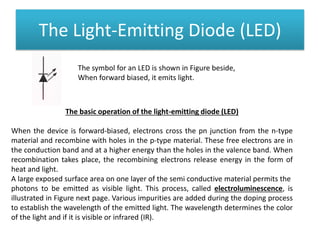
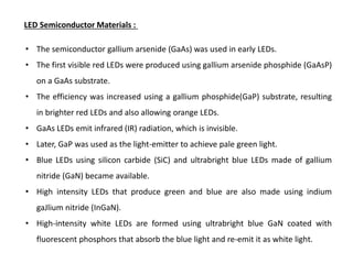
OPTICAL DIODES
Here we will,
• Discuss the operation and characteristics of LEDs and photodiodes
• Identify LED and photodiode symbols
• Explain basically how an LED emits light
• Analyze the spectral output curves and radiation patterns of LEDs
• Explain how a photodiode detects light
• Analyze the response curve of a photodiode
• Discuss photodiode sensitivity
The Light-Emitting Diode (LED)
The symbol for an LED is shown in Figure beside,
When forward biased, it emits light.
The basic operation of the light-emitting diode (LED)
When the device is forward-biased, electrons cross the pn junction from the n-type
material and recombine with holes in the p-type material. These free electrons are in
the conduction band and at a higher energy than the holes in the valence band. When
recombination takes place, the recombining electrons release energy in the form of
heat and light.
A large exposed surface area on one layer of the semi conductive material permits the
photons to be emitted as visible light. This process, called electroluminescence, is
illustrated in Figure next page. Various impurities are added during the doping process
to establish the wavelength of the emitted light. The wavelength determines the color
of the light and if it is visible or infrared (IR).
LED Semiconductor Materials :
• The semiconductor gallium arsenide (GaAs) was used in early LEDs.
• The first visible red LEDs were produced using gallium arsenide phosphide (GaAsP)
on a GaAs substrate.
• The efficiency was increased using a gallium phosphide(GaP) substrate, resulting
in brighter red LEDs and also allowing orange LEDs.
• GaAs LEDs emit infrared (IR) radiation, which is invisible.
• Later, GaP was used as the light-emitter to achieve pale green light.
• Blue LEDs using silicon carbide (SiC) and ultrabright blue LEDs made of gallium
nitride (GaN) became available.
• High intensity LEDs that produce green and blue are also made using indium
gaJlium nitride (InGaN).
• High-intensity white LEDs are formed using ultrabright blue GaN coated with
fluorescent phosphors that absorb the blue light and re-emit it as white light.
LED Characteristics
The forward bias Voltage-Current (V-I) curve and the output characteristics curve is
shown in the figure above. The V-I curve is practically applicable in burglar alarms.
Forward bias of approximately 1 volt is needed to give significant forward current.
The second figure is used to represent a radiant power-forward current curve. The
output power produced is very small and thus the efficiency in electrical-to-radiant
energy conversion is very less.
The commercially used LED‘s have a typical voltage drop between 1.5 Volt to 2.5 Volt
or current between 10 to 50 milli-amperes. The exact voltage drop depends on the
LED current, colour, tolerance, and so on.
Light Emission
The wavelength of light determines whether it is visible or infrared. An LED emits light
over a specified range of wavelengths as indicated by the spectral output curves in
Figures below. The curves in part (a) represent the light output versus wavelength for
typical visible LEDs, and the curve in part (b) is for a typical infrared LED. The
wavelength (A) is expressed in nanometers (nm). The normalized output of the visible
red LED peaks at 660 nm, the yellow at 590 nm, green at 540 nm, and blue at 460 nm.
The output for the infrared LED peaks at 940 nm.
The Photodiode
• A photodiode is a type of photo detector capable of converting light into either
current or voltage, depending upon the mode of operation.
• A photodiode is designed to operate in reverse bias.
• The common, traditional solar cell used to generate electric solar power is a large
area photodiode.
Principle of operation:
The photodiode is a device that operates in reverse bias. as shown in Figure (a) pre-page,
where Iλ is the reverse current. The photodiode has a small transparent window that
allows light to strike the pn junction. Recall that when reverse-biased. a rectifier diode has
a very small reverse leakage current. The same is true for a photodiode. The reverse-
biased current is produced by thermally generated electron-hole pairs in the depletion
region(The depletion region width is large). which are swept across the pn junction by the
electric field created by the reverse voltage. In a rectifier diode, the reverse leakage
current increases with temperature due to an increase in the number of electron-hole
pairs. Photons in the light bombard the p-n junction and some energy s imparted to the
valence electrons. So valence electrons break covalent bonds and become free electrons.
Thus more electron-hole pairs are generated. Thus total number of minority charge
carriers increases and hence reverse current increases. This is the basic principle of
operation of photodiode.
A photodiode differs from a rectifier diode in that when its pn junction is exposed to light,
the reverse current increases with the light intensity. When there is no incident light.
the reverse current, Iλ is almost negligible and is called the dark current. An increase in
the amount of light intensity, expressed as irradiance (mW/cm 2 ), produces an increase
in the reverse current,
Characteristics of photodiode:
When the P-N junction is reverse-biased, a
reverse saturation current flows due to
thermally generated holes and electrons being
swept across the junction as the minority
carriers. With the increase in temperature of the
junction more and more hole-electron pairs are
created and so the reverse saturation current I0
increases. The same effect can be had by
illuminating the junction. When light energy
bombards a P-N junction, it dislodges valence
electrons.
The more light striking the junction the larger the reverse current in a diode. It is due to
generation of more and more charge carriers with the increase in level of illumination. This
is clearly shown in figure for different intensity levels. The dark current is the current that
exists when no light is incident. It is to be noted here that current becomes zero only with a
positive applied bias equals to VQ. The almost equal spacing between the curves for the
same increment in luminous flux reveals that the reverse saturation current I0 increases
linearly with the luminous flux as shown in figure. Increase in reverse voltage does not
increase the reverse current significantly, because all available charge carriers are already
being swept across the junction. For reducing the reverse saturation current I0 to zero, it is
necessary to forward bias the junction by an amount equal to barrier potential. Thus the
photodiode can be used as a photoconductive device.
Advantages:
The advantages of photodiode are:
1. It can be used as variable resistance device.
2. Highly sensitive to the light.
3. The speed of operation is very high.
Disadvantages:
1.Temperature dependent dark current.
2.poor temperature stability.
3.Current needs amplification for driving other circuits.
Applications:
1.Alarm system.
2.counting system.
OPTICAL COUPLERS
Optical couplers use various optical devices such as LEDs and laser diodes. They are
designed to provide complete electrical isolation between an input circuit and an
output circuit. The usual purpose of isolation is to provide protection from high-
voltage transients. surge voltage, or low-level noise that could possibly result in an
erroneous output or damage to the device.
Here we will,
• Discuss various types of optical couplers
• Explain these parameters: isolation voltage, dc current transfer ratio, LED trigger
current, and transfer gain
The input circuit of an optical coupler is typically an LED, but the output circuit can take
several forms, such as the phototransistor shown in Figure (a). When the input voltage
forward-biases the LED. light transmitted to the phototransistor turns it on, producing
current through the external load, as shown in Figure (b). Typical optical couplers are
shown in Figure (c) below.
Several other types of optical couplers are
shown here.
The darlington transistor coupler in Figure (a)
can be used when increased output current
capability is needed beyond that provided by
the phototransistor output. The disadvantage
is that the photo darlington has a switching
speed less than that of the phototransistor.
A LASCR output coupler is shown in Figure (b).
This device can be used in applications where,
for example. a low-level input voltage is
required to latch a high-voltage relay for the
purpose of activating some type of
electromechanical device.
A phototriac output coupler is illustrated in Figure (c).
This device is designed for applications that require
isolated triac triggering, such as switching a 110 V ac
line from a low-level input.
Figure (d) shows an optically isolated ac linear coupler.
This device converts an input current variation to an
output voltage variation. The output circuit consists of
an amplifier with a photodiode across its input
terminals. Light variations emitted from the LED are
picked up by the photodiode. providing an input signal
to the amplifier. The output of the amplifier is
buffered with the emitter-follower stage. The optically
isolated ac linear coupler can be used for telephone
line coupling. peripheral equipment isolation, and
audio applications.
Figure (e) shows a digital output coupler. This device consists of a high-speed detector
circuit followed by a transistor buffer stage. When there is current through the input
LED, the detector is light-activated and turns on the output transistor, so that the
collector switches to a low-voltage level. When there is no current through the LED,
the output is at the high-voltage level. The digital output coupler can be used in
applications that require compatibility with digital circuits, such as interfacing
computer terminals with peripheral devices.
Isolation Voltage : The isolation voltage of an optical coupler is the maximum
voltage that can exist between the input and output terminals without dielectric
breakdown occurring.
Typical values are about 7500 V ac peak.
DC Current Transfer Ratio: This parameter is the ratio of the output current to the input
current through the LED. It is usually expressed as a percentage. For a phototransistor
output, typical values range from 2 percent to 100 percent. For a photo darlington
output, typical values range from 50 percent to 500 percent.
LED Trigger Current : This parameter applies to the LASCR output coupler and the photo
triac output device. The Trigger current is the value of current required to trigger the
thyristor output device. Typically, the trigger current is in the mA range.
Transfer Gain : This parameter applies to the optically isolated ac linear coupler. The
transfer gain is the ratio of output voltage to input current. and a typical value is 200 mV
/mA.
The key advantage of the photocoupler is the electrical isolation between two circuits. It is
employed to couple circuits whose voltage level may differ by several thousand volts.
FIBER OPTICS
Fiber-optic cables are replacing copper wire as a means of sending signals over long
distances. Fiber optics is used by cable television. telephone, and electric utility
companies, among others.
Instead of using electrical pulses to transmit information through copper lines, fiber
optics uses light pulses to transmit information through fiber-optic cables about the
diameter of a human hair, which is about 100 microns (one millionth of a meter).
Fiber-optic systems have several advantages over systems using copper wire. These
include faster speed, higher signal capacity, longer transmission distances without
amplification. less susceptibility to interference. and they are more economical to
maintain.
Here we will,
• Discuss fiber-optic cables
• Describe how signals are sent through a fiber-optic cable
• Define the basic types of fiber-optic cable
Basic Operation
When light is introduced into one end of a fiber-optic cable, it "bounces" along until it
emerges from the other end. The fiber is generally made of pure glass or plastic that is
surrounded by a highly reflective cladding that acts essentially as a mirrored surface.
Think of a fiber-optic cable as a pipe lined inside with a mirror. As the light moves along
the fiber. It is reflected off the cladding so that it can move around bends in the fiber with
essentially no loss. A fiber-optic cable consists of the core. which is the glass fiber itself.
the cladding that surrounds the fiber and provides the reflective surface, and the outer
coating or jacket that provides protection. Other layers may be added for strengthening.
The basic structure of a single fiber-optic cable is illustrated in Figure (a), and the
propagation of light along a fiber with a bend is shown in Figure (b). It doesn’t matter
whether the fiber is straight or bent; the light still travels through it.
When a light ray enters the fiber-optic cable, it strikes the reflective surface of the
cladding at an angle called the angle of incidence, i e, If the angle of incidence is
greater than a parameter known as the critical angle, θc the light ray is then reflected
back into the core at an angle called the angle of reflection, as shown in Figure(a). The
angle of incidence is always equal to the angle of reflection. If the angle of incidence is
less than the critical angle. the light ray is refracted and passes into the cladding,
causing energy to be lost, as shown in Figure (b). This is called scattering and any
refracted light represents a loss or attenuation as a light ray is propagated through the
fiber-optic cable. Another cause of attenuation of light in a fiber-optic cable is called
absorption, which is caused by the interactions of the light photons and the molecules
of the core.
The core material and the cladding material each have a parameter known as the index
of refraction, which determines the critical angle. The critical angle is defined by the
formula
where n1 is the index of refraction of the core and n2 is the index of refraction of the
cladding.
Modes of light Propagation
Three basic modes of light propagation in fiber-optic cables are multimode step index,
single-mode step index, and multimode graded index,
Multimode Step Index :
Figure 1 shows a fiber-optic cable in which the diameter of the core is fairly large relative
to the diameter of the cladding. As shown, there is a sharp transition in the index of
refraction going from the core to the cladding, thus the term step. Light entering the
cable will tend to propagate through the core in multiple rays or modes. as indicated.
Some of the rays will go straight down the core while others will bounce back and forth
as they propagate. Still others will scatter due to their small angle of incidence, causing
attenuation in the light energy. As a result of the multiple modes, the light will encounter
time dispersion; that is. all the light rays will not arrive at the end of the cable at exactly
the same time.
FIGURE 1
Multimode step index fiber-optic cable.
Single-Mode Step Index :
Figure 2 shows a fiber-optic cable in which the diameter core is very small relative to
the diameter of the cladding. There is a sharp transition in the index of refraction
going from the core to the cladding. Light entering the cable tends to propagate
through the core in a single ray or mode. This results in much less attenuation and,
ideally, no time dispersion compared to the multimode cable.
FIGURE 2
Single-mode step index fiber-optic cable.
Multimode Graded Index :
Figure 3 shows a fiber-optic cable in which the diameter of the core is fairly large relative
to the diameter of the cladding. There is a gradual or graded transition in the index of
refraction going from the center of the core into the cladding. Light rays will be more
curved as they bounce through the gradually changing indices of refraction resulting in
less attenuation and time dispersion than in the multimode step index cable.
FIGURE 3
Multimode graded index fiber-optic cable.
A Fiber-Optic Data Communications link
A simplified block diagram of a fiber-optic data communications link is shown in Figure 4.
The source provides the electrical signal that is to be transmitted. This electrical signal is
converted to a light signal and coupled to the fiber-optic cable by the transmitter. At the
receiving end, the light signal is coupled out of the cable into the receiver, which
converts it to an electrical signal. This signal is then processed and connected to the end
user.
The electrical signal modulates the light intensity and produces a light signal that carries
the same information as the electrical signal. A special connector then couples the light
signal into the fiber-optic cable. At the other end the receiver demodulates the light
signal and converts it back into the original electrical signal.
FIGURE 4
Basic block diagram of a fiber-optic data communication link.
Liquid Crystal Display (LCD)
Liquid Crystal Display is a flat electronic display which is very commonly used in digital
watches, calculators, laptops, televisions etc. It make use of light modulating
properties of liquid crystal and polarization of light for its operation. Low power
consumption, less thickness and less weight of LCD enables its use in battery powered
and portable applications.
By Definition
The LCD is defined as the diode that uses small cells and the ionised gases for the
production of images. The LCD works on the modulating property of light. The light
modulation is the technique of sending and receiving the signal through the light. The
liquid crystal consumes a small amount of energy because they are the reflector and
the transmitter of light. It is normally used for seven segmental display.
Liquid Crystal
As the name indicates Liquid Crystals exists in a state between crystalline (solid) and
isotropic (liquid) state. Among many phases, Nematic is a simplest form of liquid crystal
phase which is employed in LCD technology.
Molecules of liquid crystal are long and cylindrical in shape. Each molecules in a plane are
arranged in such a way that the major axis of each molecules are parallel to each other.
Orientation of molecules in each plane will be slightly different from the molecular
orientation of adjacent planes as shown in the below diagram. This difference in
molecular orientation in different planes will cause twisting the polarization of lights
when it passes through it.
Liquid crystals are affected by electric field, when we apply a voltage it will react and
change its arrangement. This unique behaviour of liquid crystals made the key to LCDs.
Liquid Crystal Phases Orientation of Molecules – Liquid Crystal
ON Pixel or Segment
In the above image we can see that molecules in each plane have different orientation
without electric fields. So the polarisation of light changes when it passes through liquid
crystal without electric field.
OFF Pixel or Segment
When an electric field is applied, we can see that all the molecules are arranged parallel
to the same axis. So there will not be any change in the polarization of light when it
passes through liquid crystal in an electric field.
Basic Components of LCD Panel
LCD panel looks like a piece of
glass and it is commonly called as
LCD Glass (displays used in
calculators). It is constructed of
different layers as shown in the
diagram beside.
As explained before, the twist in
light polarization created by the
liquid crystal is the basis of LCD
operation. Now let’s see the
detailed working. There are
basically two types of LCD
displays, Transmissive and
Reflective.
Transmissive Displays
It is easy to understand the working of transmissive LCD display from the illustration
(pre-page) of a segment. At the left side we can see a light source which is emitting un-
polarized light. When it passes through the rear polarizer (say vertical polarizer), the light
will become vertically polarized. Then this light enters to the liquid crystal. As we seen
before, liquid crystal will twist the polarization if it is ON. So when the vertically polarized
light passes through ON liquid crystal segment, it becomes horizontally polarized. Next is
front polarizer (say vertical polarizer), which will block horizontally polarized light. So
that segment will appear as dark for the observer. If the liquid crystal segment is OFF, it
will not change the polarization of light, so it will remain vertically polarized. So the front
polarizer will pass that light. So it will appear as bright (not dark) for the observer.
This displays allows the use of back lights,
commonly known as Backlit LCDs. We can also
use ambient light as the source as used in the
device shown beside.
Reflective Displays
The working is similar to the transmissive displays except that the light source and the
observer are in the same side. There is a reflector on the other side which will reflect back
the light from the front side.
Advantages of an LCD’s:
LCD’s consumes less amount of power compared to CRT and LED
LCD’s are consist of some microwatts for display in comparison to some mill watts for LED’s
LCDs are of low cost
Provides excellent contrast
LCD’s are thinner and lighter when compared to cathode-ray tube and LED
Disadvantages of an LCD’s:
Require additional light sources
Range of temperature is limited for operation
Low reliability
Speed is very low
LCD’s need an AC drive
Applications of Liquid Crystal Display
Liquid crystal technology has major applications in the field of science and engineering
as well on electronic devices.
Liquid crystal thermometer
Optical imaging
The liquid crystal display technology is also applicable in the visualization of the radio
frequency waves in the waveguide
Used in the medical applications

KN_Sem2_LED LCD etc.pdf

  • 1.
    OPTICAL DIODES Here wewill, • Discuss the operation and characteristics of LEDs and photodiodes • Identify LED and photodiode symbols • Explain basically how an LED emits light • Analyze the spectral output curves and radiation patterns of LEDs • Explain how a photodiode detects light • Analyze the response curve of a photodiode • Discuss photodiode sensitivity
  • 2.
    The Light-Emitting Diode(LED) The symbol for an LED is shown in Figure beside, When forward biased, it emits light. The basic operation of the light-emitting diode (LED) When the device is forward-biased, electrons cross the pn junction from the n-type material and recombine with holes in the p-type material. These free electrons are in the conduction band and at a higher energy than the holes in the valence band. When recombination takes place, the recombining electrons release energy in the form of heat and light. A large exposed surface area on one layer of the semi conductive material permits the photons to be emitted as visible light. This process, called electroluminescence, is illustrated in Figure next page. Various impurities are added during the doping process to establish the wavelength of the emitted light. The wavelength determines the color of the light and if it is visible or infrared (IR).
  • 4.
    LED Semiconductor Materials: • The semiconductor gallium arsenide (GaAs) was used in early LEDs. • The first visible red LEDs were produced using gallium arsenide phosphide (GaAsP) on a GaAs substrate. • The efficiency was increased using a gallium phosphide(GaP) substrate, resulting in brighter red LEDs and also allowing orange LEDs. • GaAs LEDs emit infrared (IR) radiation, which is invisible. • Later, GaP was used as the light-emitter to achieve pale green light. • Blue LEDs using silicon carbide (SiC) and ultrabright blue LEDs made of gallium nitride (GaN) became available. • High intensity LEDs that produce green and blue are also made using indium gaJlium nitride (InGaN). • High-intensity white LEDs are formed using ultrabright blue GaN coated with fluorescent phosphors that absorb the blue light and re-emit it as white light.
  • 5.
    LED Characteristics The forwardbias Voltage-Current (V-I) curve and the output characteristics curve is shown in the figure above. The V-I curve is practically applicable in burglar alarms. Forward bias of approximately 1 volt is needed to give significant forward current. The second figure is used to represent a radiant power-forward current curve. The output power produced is very small and thus the efficiency in electrical-to-radiant energy conversion is very less. The commercially used LED‘s have a typical voltage drop between 1.5 Volt to 2.5 Volt or current between 10 to 50 milli-amperes. The exact voltage drop depends on the LED current, colour, tolerance, and so on.
  • 6.
    Light Emission The wavelengthof light determines whether it is visible or infrared. An LED emits light over a specified range of wavelengths as indicated by the spectral output curves in Figures below. The curves in part (a) represent the light output versus wavelength for typical visible LEDs, and the curve in part (b) is for a typical infrared LED. The wavelength (A) is expressed in nanometers (nm). The normalized output of the visible red LED peaks at 660 nm, the yellow at 590 nm, green at 540 nm, and blue at 460 nm. The output for the infrared LED peaks at 940 nm.
  • 8.
    The Photodiode • Aphotodiode is a type of photo detector capable of converting light into either current or voltage, depending upon the mode of operation. • A photodiode is designed to operate in reverse bias. • The common, traditional solar cell used to generate electric solar power is a large area photodiode.
  • 9.
    Principle of operation: Thephotodiode is a device that operates in reverse bias. as shown in Figure (a) pre-page, where Iλ is the reverse current. The photodiode has a small transparent window that allows light to strike the pn junction. Recall that when reverse-biased. a rectifier diode has a very small reverse leakage current. The same is true for a photodiode. The reverse- biased current is produced by thermally generated electron-hole pairs in the depletion region(The depletion region width is large). which are swept across the pn junction by the electric field created by the reverse voltage. In a rectifier diode, the reverse leakage current increases with temperature due to an increase in the number of electron-hole pairs. Photons in the light bombard the p-n junction and some energy s imparted to the valence electrons. So valence electrons break covalent bonds and become free electrons. Thus more electron-hole pairs are generated. Thus total number of minority charge carriers increases and hence reverse current increases. This is the basic principle of operation of photodiode. A photodiode differs from a rectifier diode in that when its pn junction is exposed to light, the reverse current increases with the light intensity. When there is no incident light. the reverse current, Iλ is almost negligible and is called the dark current. An increase in the amount of light intensity, expressed as irradiance (mW/cm 2 ), produces an increase in the reverse current,
  • 10.
    Characteristics of photodiode: Whenthe P-N junction is reverse-biased, a reverse saturation current flows due to thermally generated holes and electrons being swept across the junction as the minority carriers. With the increase in temperature of the junction more and more hole-electron pairs are created and so the reverse saturation current I0 increases. The same effect can be had by illuminating the junction. When light energy bombards a P-N junction, it dislodges valence electrons. The more light striking the junction the larger the reverse current in a diode. It is due to generation of more and more charge carriers with the increase in level of illumination. This is clearly shown in figure for different intensity levels. The dark current is the current that exists when no light is incident. It is to be noted here that current becomes zero only with a positive applied bias equals to VQ. The almost equal spacing between the curves for the same increment in luminous flux reveals that the reverse saturation current I0 increases linearly with the luminous flux as shown in figure. Increase in reverse voltage does not increase the reverse current significantly, because all available charge carriers are already being swept across the junction. For reducing the reverse saturation current I0 to zero, it is necessary to forward bias the junction by an amount equal to barrier potential. Thus the photodiode can be used as a photoconductive device.
  • 12.
    Advantages: The advantages ofphotodiode are: 1. It can be used as variable resistance device. 2. Highly sensitive to the light. 3. The speed of operation is very high. Disadvantages: 1.Temperature dependent dark current. 2.poor temperature stability. 3.Current needs amplification for driving other circuits. Applications: 1.Alarm system. 2.counting system.
  • 13.
    OPTICAL COUPLERS Optical couplersuse various optical devices such as LEDs and laser diodes. They are designed to provide complete electrical isolation between an input circuit and an output circuit. The usual purpose of isolation is to provide protection from high- voltage transients. surge voltage, or low-level noise that could possibly result in an erroneous output or damage to the device. Here we will, • Discuss various types of optical couplers • Explain these parameters: isolation voltage, dc current transfer ratio, LED trigger current, and transfer gain
  • 14.
    The input circuitof an optical coupler is typically an LED, but the output circuit can take several forms, such as the phototransistor shown in Figure (a). When the input voltage forward-biases the LED. light transmitted to the phototransistor turns it on, producing current through the external load, as shown in Figure (b). Typical optical couplers are shown in Figure (c) below.
  • 15.
    Several other typesof optical couplers are shown here. The darlington transistor coupler in Figure (a) can be used when increased output current capability is needed beyond that provided by the phototransistor output. The disadvantage is that the photo darlington has a switching speed less than that of the phototransistor. A LASCR output coupler is shown in Figure (b). This device can be used in applications where, for example. a low-level input voltage is required to latch a high-voltage relay for the purpose of activating some type of electromechanical device.
  • 16.
    A phototriac outputcoupler is illustrated in Figure (c). This device is designed for applications that require isolated triac triggering, such as switching a 110 V ac line from a low-level input. Figure (d) shows an optically isolated ac linear coupler. This device converts an input current variation to an output voltage variation. The output circuit consists of an amplifier with a photodiode across its input terminals. Light variations emitted from the LED are picked up by the photodiode. providing an input signal to the amplifier. The output of the amplifier is buffered with the emitter-follower stage. The optically isolated ac linear coupler can be used for telephone line coupling. peripheral equipment isolation, and audio applications.
  • 17.
    Figure (e) showsa digital output coupler. This device consists of a high-speed detector circuit followed by a transistor buffer stage. When there is current through the input LED, the detector is light-activated and turns on the output transistor, so that the collector switches to a low-voltage level. When there is no current through the LED, the output is at the high-voltage level. The digital output coupler can be used in applications that require compatibility with digital circuits, such as interfacing computer terminals with peripheral devices.
  • 18.
    Isolation Voltage :The isolation voltage of an optical coupler is the maximum voltage that can exist between the input and output terminals without dielectric breakdown occurring. Typical values are about 7500 V ac peak. DC Current Transfer Ratio: This parameter is the ratio of the output current to the input current through the LED. It is usually expressed as a percentage. For a phototransistor output, typical values range from 2 percent to 100 percent. For a photo darlington output, typical values range from 50 percent to 500 percent. LED Trigger Current : This parameter applies to the LASCR output coupler and the photo triac output device. The Trigger current is the value of current required to trigger the thyristor output device. Typically, the trigger current is in the mA range. Transfer Gain : This parameter applies to the optically isolated ac linear coupler. The transfer gain is the ratio of output voltage to input current. and a typical value is 200 mV /mA. The key advantage of the photocoupler is the electrical isolation between two circuits. It is employed to couple circuits whose voltage level may differ by several thousand volts.
  • 19.
    FIBER OPTICS Fiber-optic cablesare replacing copper wire as a means of sending signals over long distances. Fiber optics is used by cable television. telephone, and electric utility companies, among others. Instead of using electrical pulses to transmit information through copper lines, fiber optics uses light pulses to transmit information through fiber-optic cables about the diameter of a human hair, which is about 100 microns (one millionth of a meter). Fiber-optic systems have several advantages over systems using copper wire. These include faster speed, higher signal capacity, longer transmission distances without amplification. less susceptibility to interference. and they are more economical to maintain. Here we will, • Discuss fiber-optic cables • Describe how signals are sent through a fiber-optic cable • Define the basic types of fiber-optic cable
  • 20.
    Basic Operation When lightis introduced into one end of a fiber-optic cable, it "bounces" along until it emerges from the other end. The fiber is generally made of pure glass or plastic that is surrounded by a highly reflective cladding that acts essentially as a mirrored surface. Think of a fiber-optic cable as a pipe lined inside with a mirror. As the light moves along the fiber. It is reflected off the cladding so that it can move around bends in the fiber with essentially no loss. A fiber-optic cable consists of the core. which is the glass fiber itself. the cladding that surrounds the fiber and provides the reflective surface, and the outer coating or jacket that provides protection. Other layers may be added for strengthening. The basic structure of a single fiber-optic cable is illustrated in Figure (a), and the propagation of light along a fiber with a bend is shown in Figure (b). It doesn’t matter whether the fiber is straight or bent; the light still travels through it.
  • 21.
    When a lightray enters the fiber-optic cable, it strikes the reflective surface of the cladding at an angle called the angle of incidence, i e, If the angle of incidence is greater than a parameter known as the critical angle, θc the light ray is then reflected back into the core at an angle called the angle of reflection, as shown in Figure(a). The angle of incidence is always equal to the angle of reflection. If the angle of incidence is less than the critical angle. the light ray is refracted and passes into the cladding, causing energy to be lost, as shown in Figure (b). This is called scattering and any refracted light represents a loss or attenuation as a light ray is propagated through the fiber-optic cable. Another cause of attenuation of light in a fiber-optic cable is called absorption, which is caused by the interactions of the light photons and the molecules of the core. The core material and the cladding material each have a parameter known as the index of refraction, which determines the critical angle. The critical angle is defined by the formula where n1 is the index of refraction of the core and n2 is the index of refraction of the cladding.
  • 22.
    Modes of lightPropagation Three basic modes of light propagation in fiber-optic cables are multimode step index, single-mode step index, and multimode graded index, Multimode Step Index : Figure 1 shows a fiber-optic cable in which the diameter of the core is fairly large relative to the diameter of the cladding. As shown, there is a sharp transition in the index of refraction going from the core to the cladding, thus the term step. Light entering the cable will tend to propagate through the core in multiple rays or modes. as indicated. Some of the rays will go straight down the core while others will bounce back and forth as they propagate. Still others will scatter due to their small angle of incidence, causing attenuation in the light energy. As a result of the multiple modes, the light will encounter time dispersion; that is. all the light rays will not arrive at the end of the cable at exactly the same time. FIGURE 1 Multimode step index fiber-optic cable.
  • 23.
    Single-Mode Step Index: Figure 2 shows a fiber-optic cable in which the diameter core is very small relative to the diameter of the cladding. There is a sharp transition in the index of refraction going from the core to the cladding. Light entering the cable tends to propagate through the core in a single ray or mode. This results in much less attenuation and, ideally, no time dispersion compared to the multimode cable. FIGURE 2 Single-mode step index fiber-optic cable.
  • 24.
    Multimode Graded Index: Figure 3 shows a fiber-optic cable in which the diameter of the core is fairly large relative to the diameter of the cladding. There is a gradual or graded transition in the index of refraction going from the center of the core into the cladding. Light rays will be more curved as they bounce through the gradually changing indices of refraction resulting in less attenuation and time dispersion than in the multimode step index cable. FIGURE 3 Multimode graded index fiber-optic cable.
  • 25.
    A Fiber-Optic DataCommunications link A simplified block diagram of a fiber-optic data communications link is shown in Figure 4. The source provides the electrical signal that is to be transmitted. This electrical signal is converted to a light signal and coupled to the fiber-optic cable by the transmitter. At the receiving end, the light signal is coupled out of the cable into the receiver, which converts it to an electrical signal. This signal is then processed and connected to the end user. The electrical signal modulates the light intensity and produces a light signal that carries the same information as the electrical signal. A special connector then couples the light signal into the fiber-optic cable. At the other end the receiver demodulates the light signal and converts it back into the original electrical signal. FIGURE 4 Basic block diagram of a fiber-optic data communication link.
  • 26.
    Liquid Crystal Display(LCD) Liquid Crystal Display is a flat electronic display which is very commonly used in digital watches, calculators, laptops, televisions etc. It make use of light modulating properties of liquid crystal and polarization of light for its operation. Low power consumption, less thickness and less weight of LCD enables its use in battery powered and portable applications. By Definition The LCD is defined as the diode that uses small cells and the ionised gases for the production of images. The LCD works on the modulating property of light. The light modulation is the technique of sending and receiving the signal through the light. The liquid crystal consumes a small amount of energy because they are the reflector and the transmitter of light. It is normally used for seven segmental display.
  • 27.
    Liquid Crystal As thename indicates Liquid Crystals exists in a state between crystalline (solid) and isotropic (liquid) state. Among many phases, Nematic is a simplest form of liquid crystal phase which is employed in LCD technology. Molecules of liquid crystal are long and cylindrical in shape. Each molecules in a plane are arranged in such a way that the major axis of each molecules are parallel to each other. Orientation of molecules in each plane will be slightly different from the molecular orientation of adjacent planes as shown in the below diagram. This difference in molecular orientation in different planes will cause twisting the polarization of lights when it passes through it. Liquid crystals are affected by electric field, when we apply a voltage it will react and change its arrangement. This unique behaviour of liquid crystals made the key to LCDs. Liquid Crystal Phases Orientation of Molecules – Liquid Crystal
  • 28.
    ON Pixel orSegment In the above image we can see that molecules in each plane have different orientation without electric fields. So the polarisation of light changes when it passes through liquid crystal without electric field.
  • 29.
    OFF Pixel orSegment When an electric field is applied, we can see that all the molecules are arranged parallel to the same axis. So there will not be any change in the polarization of light when it passes through liquid crystal in an electric field.
  • 30.
    Basic Components ofLCD Panel LCD panel looks like a piece of glass and it is commonly called as LCD Glass (displays used in calculators). It is constructed of different layers as shown in the diagram beside. As explained before, the twist in light polarization created by the liquid crystal is the basis of LCD operation. Now let’s see the detailed working. There are basically two types of LCD displays, Transmissive and Reflective.
  • 31.
  • 32.
    It is easyto understand the working of transmissive LCD display from the illustration (pre-page) of a segment. At the left side we can see a light source which is emitting un- polarized light. When it passes through the rear polarizer (say vertical polarizer), the light will become vertically polarized. Then this light enters to the liquid crystal. As we seen before, liquid crystal will twist the polarization if it is ON. So when the vertically polarized light passes through ON liquid crystal segment, it becomes horizontally polarized. Next is front polarizer (say vertical polarizer), which will block horizontally polarized light. So that segment will appear as dark for the observer. If the liquid crystal segment is OFF, it will not change the polarization of light, so it will remain vertically polarized. So the front polarizer will pass that light. So it will appear as bright (not dark) for the observer. This displays allows the use of back lights, commonly known as Backlit LCDs. We can also use ambient light as the source as used in the device shown beside.
  • 33.
    Reflective Displays The workingis similar to the transmissive displays except that the light source and the observer are in the same side. There is a reflector on the other side which will reflect back the light from the front side.
  • 34.
    Advantages of anLCD’s: LCD’s consumes less amount of power compared to CRT and LED LCD’s are consist of some microwatts for display in comparison to some mill watts for LED’s LCDs are of low cost Provides excellent contrast LCD’s are thinner and lighter when compared to cathode-ray tube and LED Disadvantages of an LCD’s: Require additional light sources Range of temperature is limited for operation Low reliability Speed is very low LCD’s need an AC drive
  • 35.
    Applications of LiquidCrystal Display Liquid crystal technology has major applications in the field of science and engineering as well on electronic devices. Liquid crystal thermometer Optical imaging The liquid crystal display technology is also applicable in the visualization of the radio frequency waves in the waveguide Used in the medical applications