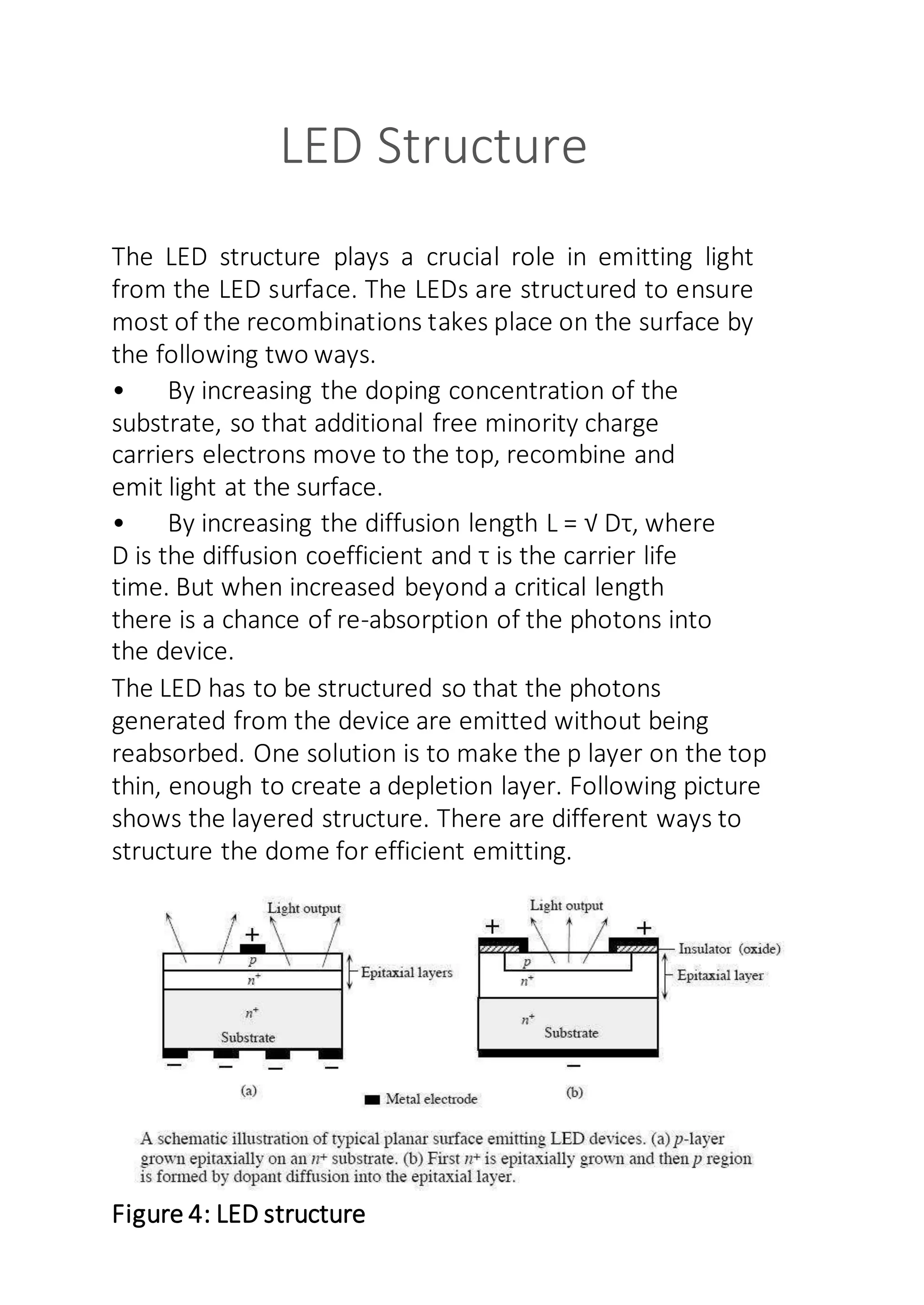
This document is a student project on light emitting diodes (LEDs) submitted to fulfill a school assignment. It includes an introduction to LEDs, their types, working principles, characteristics, structures, advantages, disadvantages, and applications. The student expresses gratitude to their teacher and principal for providing guidance and the opportunity to do the project. Certification is provided that the student completed the project according to the syllabus.
Rectifier class 12th physics investigatory projectndaashishk7781
Â
Investigatory project of physics class 12 for helping kendriya vidyalaya students
Project on rectifier whoever taking this project also requires a modal of rectifier
Rectifier class 12th physics investigatory projectndaashishk7781
Â
Investigatory project of physics class 12 for helping kendriya vidyalaya students
Project on rectifier whoever taking this project also requires a modal of rectifier
This time I am presenting you Physics Investigatory Project for class 12 on the topic "TO DESIGN APPROPRIATE LOGIC GATE COMBINATION FOR GIVEN TRUTH TABLE"
TOPIC-To investigate the relation between the ratio of :-1. Input and outpu...CHMURLIDHAR
Â
TOPIC-To investigate the relation between the ratio of :-1. Input and output voltage.2. Number of turnings in the secondary coil and primary coil of a self made transformer.
Synthetic Fiber Construction in lab .pptxPavel ( NSTU)
Â
Synthetic fiber production is a fascinating and complex field that blends chemistry, engineering, and environmental science. By understanding these aspects, students can gain a comprehensive view of synthetic fiber production, its impact on society and the environment, and the potential for future innovations. Synthetic fibers play a crucial role in modern society, impacting various aspects of daily life, industry, and the environment. ynthetic fibers are integral to modern life, offering a range of benefits from cost-effectiveness and versatility to innovative applications and performance characteristics. While they pose environmental challenges, ongoing research and development aim to create more sustainable and eco-friendly alternatives. Understanding the importance of synthetic fibers helps in appreciating their role in the economy, industry, and daily life, while also emphasizing the need for sustainable practices and innovation.
The French Revolution, which began in 1789, was a period of radical social and political upheaval in France. It marked the decline of absolute monarchies, the rise of secular and democratic republics, and the eventual rise of Napoleon Bonaparte. This revolutionary period is crucial in understanding the transition from feudalism to modernity in Europe.
For more information, visit-www.vavaclasses.com
Students, digital devices and success - Andreas Schleicher - 27 May 2024..pptxEduSkills OECD
Â
Andreas Schleicher presents at the OECD webinar âDigital devices in schools: detrimental distraction or secret to success?â on 27 May 2024. The presentation was based on findings from PISA 2022 results and the webinar helped launch the PISA in Focus âManaging screen time: How to protect and equip students against distractionâ https://www.oecd-ilibrary.org/education/managing-screen-time_7c225af4-en and the OECD Education Policy Perspective âStudents, digital devices and successâ can be found here - https://oe.cd/il/5yV
Operation âBlue Starâ is the only event in the history of Independent India where the state went into war with its own people. Even after about 40 years it is not clear if it was culmination of states anger over people of the region, a political game of power or start of dictatorial chapter in the democratic setup.
The people of Punjab felt alienated from main stream due to denial of their just demands during a long democratic struggle since independence. As it happen all over the word, it led to militant struggle with great loss of lives of military, police and civilian personnel. Killing of Indira Gandhi and massacre of innocent Sikhs in Delhi and other India cities was also associated with this movement.
Instructions for Submissions thorugh G- Classroom.pptxJheel Barad
Â
This presentation provides a briefing on how to upload submissions and documents in Google Classroom. It was prepared as part of an orientation for new Sainik School in-service teacher trainees. As a training officer, my goal is to ensure that you are comfortable and proficient with this essential tool for managing assignments and fostering student engagement.
How to Make a Field invisible in Odoo 17Celine George
Â
It is possible to hide or invisible some fields in odoo. Commonly using âinvisibleâ attribute in the field definition to invisible the fields. This slide will show how to make a field invisible in odoo 17.
2. I would like to express my special thanks of gratitude
to my teacher Mr. Aditya Bera Sir as well as our
principal Mr. B. SudhakaraReddy SIR who gave me
the golden opportunityto do this wonderful project
on the topic Light EmittingDiode(LED),which also
helped me in doinga lot of Research and I came to
know about so manynew things I am really thankful
to them.
Secondly, I would also like to thankmy parents and
friends who helped me a lot in finalizingthis project
within the limited time frame.
I am making this project not only for marks but to also
increase my knowledge.
3. This is to certify that Nohar Das Tandan of class
12th
has completed his project in the subject of
Physics as required according to the syllabus as
prescribed by the central board of secondary
education (CBSE) and the guidance of Mr.
Aditya Bera (P.G.T. Physics) for the academic
session 2017-2018.
Sign. of principal Sign.of Subject Teacher
Sign. Of Extenal Teacher
4. Contents
S.No. Topics
1 Introduction
2 Types of LEDâs
3 Working of LED
4 LED I-V Characteristic
5 Multicolored LEDâs
6 LED Structure
7 Advantages of LEDâs
8 Disadvantages of LEDâs
9 Applications of LEDâs
10 Bibliography
5. Introduction
A light-emitting diode (LED) is a semiconductor device that emits
visible light when an electric current passes through it. The light is not
particularly bright, but in most LEDs it is monochromatic, occurring at
a single wavelength. The output from an LED can range from red (at a
wavelength of approximately 700 nanometers) to blue-violet (about
400 nanometers). Some LEDs emit infrared (IR) energy (830
nanometers or longer); such a device is known as an infrared-emitting
diode (IRED).
An LED or IRED consists of two elements of processed material called
P-type semiconductors and N-type semiconductors. These two
elements are placed in direct contact, forming a region called the P-N
junction. In this respect, the LED or IRED resembles most
other diode types, but there are important differences. The LED or
IRED has a transparent package, allowing visible or IR energy to
pass through. Also, the LED or IRED has a large PN-junction area
whose shape is tailored to the application.
Benefits of LEDs and IREDs, compared with incandescent
and fluorescent illuminating devices, include:
Low power requirement: Most types can be operated with
battery power supplies.
High efficiency: Most of the power supplied to an LED or IRED
is converted into radiation in the desired form, with minimal
heat production.
Long life: Whenproperly installed, an LED or IRED can function
for decades.
6. ď§
ď§
ď§
ď§
ď§
ď§
ď§
ď§
ď§
ď§
Types of LEDâs
Gallium Arsenide (GaAs) â infra-red
Gallium Arsenide Phosphide (GaAsP) â red to
infra-red, orange
Aluminium Gallium Arsenide Phosphide
(AlGaAsP) â high-brightness red, orange-red,
orange, and yellow
Gallium Phosphide (GaP) â red, yellow and green
Aluminium Gallium Phosphide (AlGaP) â green
Gallium Nitride (GaN) â green, emerald green
Gallium Indium Nitride (GaInN) â near ultraviolet,
bluish-green and blue
Silicon Carbide (SiC) â blue as a substrate
Zinc Selenide (ZnSe) â blue
Aluminium Gallium Nitride (AlGaN) â ultraviolet
7. Working Of LED
A Light emitting diode (LED) is essentially a pn junction diode. When carriers are
injected across a forward-biased junction, it emits incoherent light. Most of the
commercial LEDs are realized using a highly doped n and a p Junction.
Figure 1: p-n+ Junction under Unbiased and biased conditions.
(pn Junction Devices and Light Emitting Diodes by Safa Kasap)
To understand the principle, letâs consider an unbiased pn+ junction (Figure1 shows the pn+
energy band diagram). The depletion region extends mainly into the p-side. There is a
potential barrier from Ec on the n-side to the Ec on the p-side, called the built-in voltage,
V0. This potential barrier prevents the excess free electrons on the n+ side from diffusing
into the p side.
When a Voltage V is applied across the junction, the built-in potential is reduced from V0
to V0 â V. This allows the electrons from the n+ side to get injected into the p-side. Since
electrons are the minority carriers in the p-side, this process is called minority carrier
injection. But the hole injection from the p side to n+ side is very less and so the current is
primarily due to the flow of electrons into the p-side.
These electrons injected into the p-side recombine with the holes. This recombination
results in spontaneous emission of photons (light). This effect is called injection
electroluminescence. These photons should be allowed to escape from the device without
being reabsorbed.
The recombination can be classified into the following two kinds
⢠Direct recombination
Indirect recombination
Direct Recombination:
In direct band gap materials, the minimum energy of the conduction band lies directly
above the maximum energy of the valence band in momentum space energy (Figure 2
shows the E-k plot of a direct band gap material). In this material, free
8. electrons at the bottom of the conduction band can recombine directly with free holes at
the top of the valence band, as the momentum of the two particles is the same. This
transition from conduction band to valence band involves photon emission (takes care of
the principle of energy conservation). This is known as direct recombination. Direct
recombination occurs spontaneously. GaAs is an example of a direct band-gap material.
Figure2: Direct Bandgap and Direct Recombination
Indirect Recombination:
In the indirect band gap materials, the minimum energy in the conduction band is shifted
by a k-vector relative to the valence band. The k-vector difference represents a difference
in momentum. Due to this difference in momentum, the probability of direct electronhole
recombination is less.
In these materials, additional dopants(impurities) are added which form very shallow
donor states. These donor states capture the free electrons locally; provides the necessary
momentum shift for recombination. These donor states serve as the recombination
centers. This is called Indirect (non-radiative) Recombination.
Figure3 shows the E-k plot of an indirect band gap material and an example of how
Nitrogen serves as a recombination center in GaAsP. In this case it creates a donor state,
when SiC is doped with Al, it recombination takes place through an acceptor level.
The indirect recombination should satisfy both conservation energy, and momentum.
Thus besides a photon emission, phonon emission or absorption has to take
place.
GaP is an example of an indirect band-gap material.
9. Figure3: Indirect Bandgap and NonRadiative recombination
The wavelength of the light emitted, and hence the color, depends on the band gap energy
of the materials forming the p-n junction.
The emitted photon energy is approximately equal to the band gap energy of the
semiconductor. The following equation relates the wavelength and the energy band gap.
hν = Eg
hc/Îť = Eg
Îť = hc/ Eg
Where h is Plankâs constant, c is the speed of the light and Eg is the energy band gap
Thus, a semiconductor with a 2 eV band-gap emits light at about 620 nm, in the red. A
3 eV band-gap material would emit at 414 nm, in the violet.
LED I-V Characteristic
10. Light Emitting Diode (LED) Schematic symbol and I -V Characteristics Curves
showing the different colours available.
Before a light emitting diode can âemitâ any form of light it needs a current to flow
through it, as it is a current dependant device with their light output intensity being
directly proportional to the forward current flowing through the LED.
As the LED is to be connected in a forward bias condition across a power supply it should
be current limited using a series resistor to protect it from excessive current flow. Never
connect an LED directly to a battery or power supply as it will be destroyed almost
instantly because too much current will pass through and burn it out.
From the table above we can see that each LED has its own forward voltage drop across the
PN junction and this parameter which is determined by the semiconductor material used, is
the forward voltage drop for a specified amount of forward conduction current, typically for
a forward current of 20mA.
In most cases LEDs are operated from a low voltage DC supply, with a series resistor, RSused
to limit the forward current to a safe value from say 5mA for a simple LED indicator to
30mA or more where a high brightness light output is needed.
Multi-coloured Light Emitting Diodeâs
LEDs are available in a wide range of shapes, colours and various sizes with different light
output intensities available, with the most common (and cheapest to produce) being the
standard 5mm Red Gallium Arsenide Phosphide (GaAsP) LED.
LEDâs are also available in various âpackagesâ arranged to produce both letters and
numbers with the most common being that of the âseven segment displayâ arrangement.
Nowadays, full colour flat screen LED displays, hand held devices and TVâs are available which
use a vast number of multicoloured LEDâs all been driven directly by their own dedicated IC.
Most light emitting diodes produce just a single output of coloured light however, multi -
coloured LEDs are now available that can produce a range of different colours from within a
single device. Most of these are actually two or three LEDs fabricated within a single package.
Bicolour Light Emitting Diodes
A bicolour light emitting diode has two LEDs chips connected together in âinverse parallelâ
(one forwards, one backwards) combined in one single package. Bicolour LEDs can produce
any one of three colours for example, a red colour is emitted when the device is connected
with current flowing in one direction and a green colour is emitted when it is biased in the
other direction.
This type of bi-directional arrangement is useful for giving polarity indication, for example, the
correct connection of batteries or power supplies etc. Also, a bi-directional current produces
both colours mixed together as the two LEDs would take it in turn to illuminate if the device
was connected (via a suitable resistor) to a low voltage, low frequency AC supply.
11. A Bicolour LED
Tricoloured LightEmitting Diode
The most popular type of tricolour light emitting diode comprises of a single Red and a Green
LED combined in one package with their cathode terminals connected together producing a
three terminal device. They are called tricolour LEDs because they can give out a single red
or a green colour by turning âONâ only one LED at a time.
These tricoloured LEDâs can also generate additional shades of their primary colours (the
third colour) such as Orange or Yellow by turning âONâ the two LEDs in different ratios of
forward current as shown in the table thereby generating 4 different colours from just
two diode junctions.
A Multi or Tricoloured LED
12. LED Structure
The LED structure plays a crucial role in emitting light
from the LED surface. The LEDs are structured to ensure
most of the recombinations takes place on the surface by
the following two ways.
⢠By increasing the doping concentration of the
substrate, so that additional free minority charge
carriers electrons move to the top, recombine and
emit light at the surface.
⢠By increasing the diffusion length L = â DĎ, where
D is the diffusion coefficient and Ď is the carrier life
time. But when increased beyond a critical length
there is a chance of re-absorption of the photons into
the device.
The LED has to be structured so that the photons
generated from the device are emitted without being
reabsorbed. One solution is to make the p layer on the top
thin, enough to create a depletion layer. Following picture
shows the layered structure. There are different ways to
structure the dome for efficient emitting.
Figure 4: LED structure
13. (pn JunctionDevices andLight Emitting Diodes by Safa Kasap)
LEDs are usually built on an n-type substrate, with an
electrode attached to the p-type layer deposited on its
surface. P-type substrates, while less common, occur as
well. Many commercial LEDs, especially GaN/InGaN, also
use sapphire substrate.
LED efficiency:
A very important metric of an LED is the external quantum
efficiency Ρext. It quantifies the efficeincy of the
conversion of electrical energy into emitted optical
energy. It is defined as the light output divided by the
electrical input power. It is also defined as the product of
Internal radiative efficiency and Extraction efficiency.
Ρext = Pout(optical) / IV
For indirect bandgap semiconductors Ρext is generally less
than 1%, where as for a direct band gap material it could be
substantial.
Ρint = rate of radiation recombination/ Total recombination
The internal efficiency is a function of the quality of the
material and the structure and composition of the layer.
14. Advantages of LEDâs
â˘LEDs produce more light per watt than incandescent
bulbs; this is useful in battery powered or energy-saving
devices.
â˘LEDs can emit light of an intended color without the use
of color filters that traditional lighting methods require.
This is more efficient and can lower initial costs.
â˘The solid package of the LED can be designed to focus its
light. Incandescent and fluorescent sources often require an
external reflector to collect light and direct it in a usable
manner.
â˘When used in applications where dimming is required, LEDs
do not change their color tint as the current passing through
them is lowered, unlike incandescent lamps, which turn
yellow.
â˘LEDs are ideal for use in applications that are subject to
frequent on-off cycling, unlike fluorescent lamps that burn
out more quickly when cycled frequently, or High Intensity
Discharge (HID) lamps that require a long time before
restarting.
â˘LEDs, being solid state components, are difficult to damage with
external shock.
Fluorescent and incandescent bulbs are easily broken if dropped on
the ground.
â˘LEDs can have a relatively long useful life. A Philips LUXEON k2 LED
has a
life time of about 50,000 hours, whereas Fluorescent tubes
typically are rated at about 30,000 hours, and incandescent
light bulbs at 1,000â2,000 hours.
â˘LEDs mostly fail by dimming over time, rather than the
abrupt burn-out of incandescent bulbs.
â˘LEDs light up very quickly. A typical red indicator LED will
achieve full brightness in microseconds; Philips Lumileds
technical datasheet DS23 for the Luxeon Star states "less
than 100ns." LEDs used in communications devices can
have even faster response times.
â˘LEDs can be very small and are easily populated onto printed circuit
boards.
LEDs do not contain mercury, unlike compact fluorescent lamps.
15. Disadvantages of using LEDâs
â˘LEDs are currently more expensive, price per lumen,
on an initial capital cost basis, than more conventional
lighting technologies. The additional expense partially
stems from the relatively low lumen output and the
drive circuitry and power supplies needed. However,
when considering the total cost of ownership
(including energy and maintenance costs), LEDs far
surpass incandescent or halogen sources and begin to
threaten the future existence of compact fluorescent
lamps.
⢠LED performance largely depends on the
ambient temperature of the operating environment.
Over-driving the LED in high ambient temperatures
may result in overheating of the LED package,
eventually leading to device failure. Adequate heat-
sinking is required to maintain long life.
⢠LEDs must be supplied with the correct current.
This can involve series resistors or current-regulated
power supplies.
⢠LEDs do not approximate a "point source" of
light, so they cannot be used in applications needing
a highly collimated beam. LEDs are not capable of
providing divergence below a few degrees. This is
contrasted with commercial ruby lasers with
divergences of 0.2 degrees or less. However this can
be corrected by using lenses and other optical
devices.
⢠There is increasing concern that blue LEDs and
white LEDs are now capable of exceeding safe limits
of the so-called blue-light hazard as defined in the
eye safety specifications for example ANSI/IESNA RP-
27.1-05: Recommended
Practice for Photobiological Safety for Lamp and Lamp
Systems.
16. Applications of LEDâs
ďˇ Indicator lights: These can be two-state (i.e., on/off), bar-graph,
or alphabetic-numeric readouts.ď
ď
ď
ďˇ LCD panel backlighting: Specialized white LEDs are used in flat-
panel computer displays.ď
ď
ď
Fiber optic data transmission: Ease of modulation allows wide
communications bandwidth with minimal noise, resulting in high
speed and accuracy.
ďˇ Remote control: Mosthome-entertainment "remotes" use IREDs
to transmit data to the main unit.ď
ď
ď
Optoisolator: Stages in an electronic system can be
connected together without unwanted interaction.
17. Bibliography
The following books were used in completion of this
project.
NCERT Textbook of Physics for class 12th .
Pradeep Fundamental of Physics for class 12th .
Also, the following websites were consulted for relevant
materials.
https://www.google.co.in/
https://en.wikipedia.org
http://www.electronics-tutorials.ws/diode/diode_8.html
http://whatis.techtarget.com/definition/light-emitting-diode-LED