Downloaded 171 times
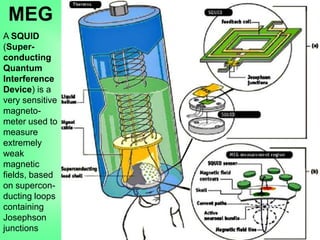
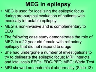
![• Application of MEG in MRI-negative non-lesional
cases provides additional information needed for
decision-making before surgery can be attempted
• The rate of +ve findings after MEG-guided review
of previously MRI-negative films is ~ 17.5%
• Because MEG is primarily sensitive to magnetic
fields generated by intracellular currents, it limits
inaccurate readings from outside sources
• Drawbacks: Major costs associated with operating
it as well as its limited availability
Poon TL, Cheung FC and Lui CH. Magnetoencephalography and its role in evaluation
for epilepsy surgery. HKMJ. 2010 February [cited 2010 March 29]; 16(1):44-47[4
pages]. Available from: http://www.hkmj.org/article_pdfs/hkm1002p44.pdf
MEG in epilepsy](https://image.slidesharecdn.com/technologicalinnovationsinneurology2-100909091851-phpapp02/85/Technological-Innovations-in-Neurology-2-Sanjoy-Sanyal-16-320.jpg)
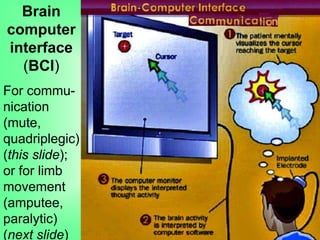
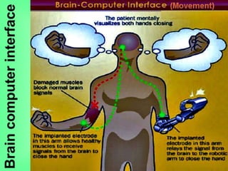
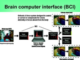
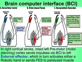
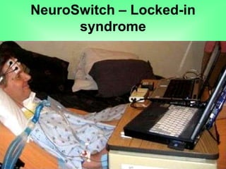
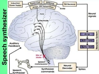
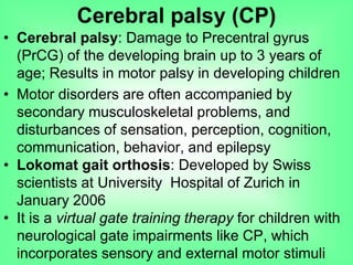
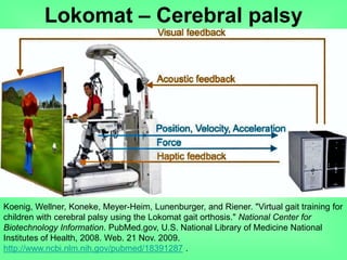


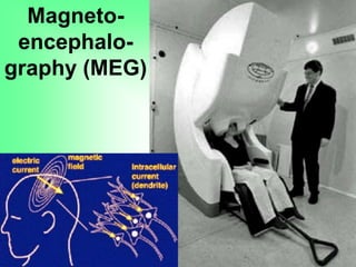
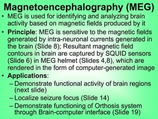
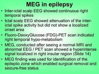
This document outlines various technological innovations in neurology presented by Dr. Sanjoy Sanyal, including magnetoencephalography (MEG) for epilepsy, brain-computer interfaces (BCI) for communication and limb movement, Lokomat orthosis for cerebral palsy rehabilitation, and Brainport systems for sensory augmentation. Each technology is discussed in terms of its applications, underlying principles, and case studies showcasing their effectiveness in addressing neurological disorders. The document also emphasizes the advancements in non-invasive techniques, their clinical significance, and potential future developments in neuroprosthetics and rehabilitation.


