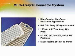
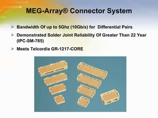
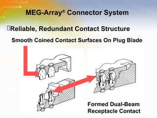
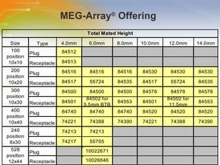
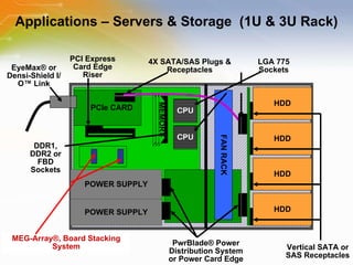
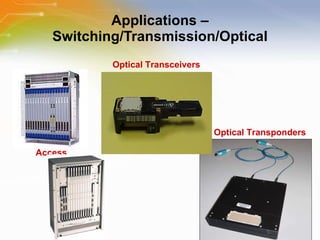
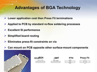
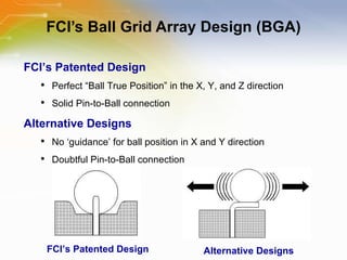
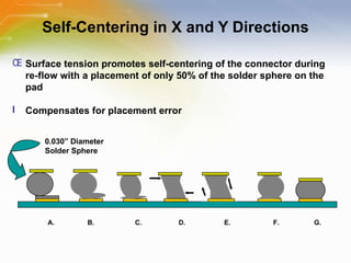
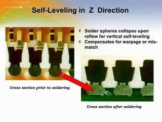
MEG-Array® Connector System Source: FCI
Introduction Purpose To introduce a high speed Mezzanine MEG Array ®  connector, its features and applications Outline Overview of MEG-Array connector system MEG-Array product portfolio Applications FCI’s BGA technology Content 17 pages
MEG-Array® Connector System High-Density, High-Speed Mezzanine Applications Ball Grid Array (BGA) Attachment 1.27mm X 1.27mm Array Grid Pitch 81, 100, 200, 240, 300, 400 & 528 Positions Stack Heights of 4mm To 14mm
MEG-Array® Connector System Bandwidth Of up to 5Ghz (10Gb/s) for  Differential Pairs Demonstrated Solder Joint Reliability Of Greater Than 22 Year (IPC-SM-785) Meets Telcordia GR-1217-CORE
MEG-Array ®  Connector System Formed Dual-Beam  Receptacle Contact Reliable, Redundant Contact Structure Smooth Coined Contact Surfaces On Plug Blade
MEG-Array ®  Offering
Applications   –   Servers   &   Storage   (1U   &   3U   Rack) POWER SUPPLY POWER SUPPLY PCIe CARD FAN RACK PwrBlade ®  Power Distribution System or Power Card Edge Vertical SATA or SAS Receptacles HDD HDD HDD HDD CPU CPU MEMORY DDR1, DDR2 or FBD Sockets PCI Express Card Edge Riser 4X SATA/SAS Plugs & Receptacles MEG-Array ®, Board Stacking System EyeMax® or Densi-Shield I/O™ Link LGA 775 Sockets
Applications   –   Switching   &   Transmission Switches Transmission   Routers
Applications   –   Switching/Transmission/Optical Access Optical   Transceivers Optical   Transponders
Applications   –   Industrial/Medical High   End   Medical   Imaging   Analytical - ECG  High-End medical imaging  CT Scan ECG MRI Cardiovascular X-Ray Radiation Oncology Photo Diodes X-ray beams
Advantages of BGA Technology Lower application cost then Press Fit terminations Applied to PCB by standard re-flow soldering processes  Excellent SI performance Simplified board routing Eliminates press-fit constraints on via Can mount on PCB opposite other surface-mount components BGA PTH SMT Press Fit   BGA
FCI’s Ball Grid Array Design (BGA) FCI’s Patented Design Alternative Designs FCI’s Patented Design Perfect “Ball True Position” in the X, Y, and Z direction Solid Pin-to-Ball connection Alternative Designs No ‘guidance’ for ball position in X and Y direction  Doubtful Pin-to-Ball connection
Self-Centering in X and Y Directions Surface tension promotes self-centering of the connector during re-flow with a placement of only 50% of the solder sphere on the pad  Compensates for placement error A.  B.  C.  D.  E.  F.  G. 0.030” Diameter Solder Sphere
Self-Leveling in  Z  Direction Cross section prior to soldering Cross section after soldering Solder spheres collapse upon reflow for vertical self-leveling Compensates for warpage or mis-match
FCI’s BGA Reliability FCI 100% verifies BGA coplanarity of every meg-array connector Solder Joint Reliability – FCI’s BGA solder joint reliability on the MEG-Array product in accordance with IPC-SM-785 is in excess of 22 years life Additional reliability testing at the PCB interface (testing conducted at an outside lab) Passed 1000 Thermal Cycles -40 º C to +85 º C Passed 1000 Thermal Cycles -25 º C to +100 º C
Summary MEG-Array Released for Mass Production in 1996 12+ Years of Volume Production Provides up to 10 Gb/s Electrical Performance Proven Patented BGA Design FCI is Recognized As The BGA Expert…Shipping over 10 Billion BGA Contacts Connectors Provide 2-Points Of Contact for Reliability  Demonstrated > 22 Years Life (IPC-SM-785) Solder Joint Reliability
Additional Resource For ordering MEG-Array connectors, please click the part list or Call our sales hotline For additional inquires contact our technical service hotline For more product information go to http://portal.fciconnect.com/portal/page/portal/FcicntPublic/MezzSelect_MegArray Newark Farnell

MEG-Array® Connector System

  • 1.
  • 2.
    Introduction Purpose Tointroduce a high speed Mezzanine MEG Array ® connector, its features and applications Outline Overview of MEG-Array connector system MEG-Array product portfolio Applications FCI’s BGA technology Content 17 pages
  • 3.
    MEG-Array® Connector SystemHigh-Density, High-Speed Mezzanine Applications Ball Grid Array (BGA) Attachment 1.27mm X 1.27mm Array Grid Pitch 81, 100, 200, 240, 300, 400 & 528 Positions Stack Heights of 4mm To 14mm
  • 4.
    MEG-Array® Connector SystemBandwidth Of up to 5Ghz (10Gb/s) for Differential Pairs Demonstrated Solder Joint Reliability Of Greater Than 22 Year (IPC-SM-785) Meets Telcordia GR-1217-CORE
  • 5.
    MEG-Array ® Connector System Formed Dual-Beam Receptacle Contact Reliable, Redundant Contact Structure Smooth Coined Contact Surfaces On Plug Blade
  • 6.
    MEG-Array ® Offering
  • 7.
    Applications – Servers & Storage (1U & 3U Rack) POWER SUPPLY POWER SUPPLY PCIe CARD FAN RACK PwrBlade ® Power Distribution System or Power Card Edge Vertical SATA or SAS Receptacles HDD HDD HDD HDD CPU CPU MEMORY DDR1, DDR2 or FBD Sockets PCI Express Card Edge Riser 4X SATA/SAS Plugs & Receptacles MEG-Array ®, Board Stacking System EyeMax® or Densi-Shield I/O™ Link LGA 775 Sockets
  • 8.
    Applications – Switching & Transmission Switches Transmission Routers
  • 9.
    Applications – Switching/Transmission/Optical Access Optical Transceivers Optical Transponders
  • 10.
    Applications – Industrial/Medical High End Medical Imaging Analytical - ECG High-End medical imaging CT Scan ECG MRI Cardiovascular X-Ray Radiation Oncology Photo Diodes X-ray beams
  • 11.
    Advantages of BGATechnology Lower application cost then Press Fit terminations Applied to PCB by standard re-flow soldering processes Excellent SI performance Simplified board routing Eliminates press-fit constraints on via Can mount on PCB opposite other surface-mount components BGA PTH SMT Press Fit BGA
  • 12.
    FCI’s Ball GridArray Design (BGA) FCI’s Patented Design Alternative Designs FCI’s Patented Design Perfect “Ball True Position” in the X, Y, and Z direction Solid Pin-to-Ball connection Alternative Designs No ‘guidance’ for ball position in X and Y direction Doubtful Pin-to-Ball connection
  • 13.
    Self-Centering in Xand Y Directions Surface tension promotes self-centering of the connector during re-flow with a placement of only 50% of the solder sphere on the pad Compensates for placement error A. B. C. D. E. F. G. 0.030” Diameter Solder Sphere
  • 14.
    Self-Leveling in Z Direction Cross section prior to soldering Cross section after soldering Solder spheres collapse upon reflow for vertical self-leveling Compensates for warpage or mis-match
  • 15.
    FCI’s BGA ReliabilityFCI 100% verifies BGA coplanarity of every meg-array connector Solder Joint Reliability – FCI’s BGA solder joint reliability on the MEG-Array product in accordance with IPC-SM-785 is in excess of 22 years life Additional reliability testing at the PCB interface (testing conducted at an outside lab) Passed 1000 Thermal Cycles -40 º C to +85 º C Passed 1000 Thermal Cycles -25 º C to +100 º C
  • 16.
    Summary MEG-Array Releasedfor Mass Production in 1996 12+ Years of Volume Production Provides up to 10 Gb/s Electrical Performance Proven Patented BGA Design FCI is Recognized As The BGA Expert…Shipping over 10 Billion BGA Contacts Connectors Provide 2-Points Of Contact for Reliability Demonstrated > 22 Years Life (IPC-SM-785) Solder Joint Reliability
  • 17.
    Additional Resource Forordering MEG-Array connectors, please click the part list or Call our sales hotline For additional inquires contact our technical service hotline For more product information go to http://portal.fciconnect.com/portal/page/portal/FcicntPublic/MezzSelect_MegArray Newark Farnell

Editor's Notes

  • #3 Welcome to the training module on MEG-Array® Connector System. This training module introduces a high speed Mezzanine MEG Array ® connector, its features and applications.
  • #4 The FCI MEG-Array Connector system is used in mezzanine applications that require high speed capability and/or high density. The unique Ball Grid Array termination is well proven and reliable. The MEG-Array connector is based on contacts in a fifty thousandths of an inch square array. It is available in contact patterns of 81, 100, 200, 240, 300, 400, and 528 positions, and in mezzanine stack heights from 4 to 14 millimeters.
  • #5 Meg-Array connectors have a bandwidth of up to 10 gigabits per second. The BGA solder joints have a demonstrated solder joint reliability in excess of 22 years and the connector system meets Telcordia requirements.
  • #6 Though the Meg-Array uses a very small contact system, it is big in performance. The contact structure provides for two points of contact when mated together, resulting in excellent contact reliability.
  • #7 This table shows currently tooled versions of Meg-Array plugs and receptacles and the various pin counts as well as stack heights that can be achieved.
  • #8 In next few pages, we will look at some applications where the FCI Meg-Array can provide a good connector interface solution. In some servers the memory or some functional options may be in the form of an add on board. The Mezzanine supporting an option board is shown here being connected by the FCI Meg-Array.
  • #9 Similar high speed and high performance mezzanine applications can be found in Switching and Transmission equipment such as large switches and Routers.
  • #10 Optical transmission equipment can be an excellent place to look for Meg-Array applications. Along with typical mezzanines, The FCI Meg-Array system is commonly used as an interface for optical transponders as well as parallel optical links, sometimes called Paroli modules. Here you see examples of these two types of products. The FCI Meg-Array is shipped in Tape and Reel packaging with an optional vacuum pick up cap, that doubles as a contact protector, an example of which is seen in the crème color Meg-Array mounted on the Optical Transceiver on this page.
  • #11 The high pin count of the FCI Meg-Array system works well in medical high end imaging applications such as CT Scanners, MRI, and Cardiovascular X-Rays as well as in Radiation Oncology ECG analysis equipment.
  • #12 The FCI patented BGA technology allows the products to achieve high density and high performance. Some of the advantages of Ball Grid Array technology include the lower applied cost when compared to press fit termination. The ability to use reflow processing allows you to terminate the connector simultaneously with other surface mount components. BGA termination helps in high speed applications since vias can be eliminated or minimized. Routing becomes easier due to minimal vias, and double sided connectorization is possible since there are no parts of the connector protruding through the board.
  • #13 FCI’s patented BGA design assures perfect solder ball location. Alternative designs provide no guidance for ball position, and don’t always assure a good connection between the solder ball and the terminal.
  • #14 Another advantage to BGA technology is the ability for the solder balls to self center on the circuit board pads during reflow. This ability can compensate for placement errors up to 50% of the pad size.
  • #15 Additionally, the solder balls will help to self level the Meg-Array connector, compensating for small variations of pad height or slight warpage of the circuit board.
  • #16 FCI verifies the coplanarity of all of the solder balls on each connector as it is manufactured. In addition, FCI has contracted an outside lab to evaluate our solder joint reliability based on IPC standards, and determined that The Meg-Array would be reliable for over 22 years.
  • #17 In summary the FCI Meg-Array connector system has proven reliability for over 12 years, and laboratory life testing shows that it should have solder joint reliability in excess of 22 years. The FCI patented ball grid array and mating interface with two points of contact assure high reliability and excellent electrical performance for many years of product service.
  • #18 Thank you for taking the time to view this presentation on “ MEG-Array® Connector System” . If you would like to learn more or go on to purchase some of these devices, you may either click on the part list link, or simply call our sales hotline. For more technical information you may either visit the FCI site – link shown, or if you would prefer to speak to someone live, please call our hotline number, or even use our ‘live chat’ online facility.