Download to read offline
![Engineering, Technology & Applied Science Research Vol. 8, No. 2, 2018, 2847-2852 2847
www.etasr.com Abdelrehim et al.: Indirect 3D-Space Vector Modulation for a Matrix Converter
Indirect 3D-Space Vector Modulation for a Matrix
Converter
Ahmed Abdelrehim
Department of Electrical Engineering
Alexandria University
Alexandria, Egypt
ahmed.abdelrehim@siemens.com
Mohamed El-Habrouk
Department of Electrical Engineering
Alexandria University
Alexandria, Egypt
eepgmme1@yahoo.com
Samir Deghedie Erfan
Department of Electrical Engineering
Alexandria University
Alexandria, Egypt
deghedie@gmail.com
Karim Hassan Youssef
Department of Electrical Engineering
Alexandria University
Alexandria, Egypt
khmyoussef@yahoo.com
Abstract—This paper discusses the indirect space vector
modulation for a four-leg matrix converter. The four-leg matrix
converter has been proven to be a reliable, cost-effective, and
compact power electronic interface to supply unbalanced or
nonlinear loads. However, the added fourth leg has shifted the
inverter side modulation from simple two-dimension SVM into
complex three-dimension. This paper employs a new technique to
implement indirect 3D SVM in digital controllers with further
simplification in the modulation process. Moreover, Simulink
simulation using repetitive controller has been performed to
regulate the output voltage for 400 Hz Power supplies.
Keywords-repetitive controller; 3D SVM; four-leg matrix
converter
I. INTRODUCTION
The matrix converter is a static and direct AC to AC
converter with unique features of unity input power factor, high
power to volume ratio, high reliability and MTBF factor which
has gained interest in applications aiming to produce a
realization of a compact three-phase drive for military,
industrial and aerospace systems [1-3]. Moreover, researchers
utilized the matrix converter as an electronic interface layer
between all resources (wind, solar, storage, etc.) of the energy
matrix model and as an electronic transformer competing with
the traditional magnetic transformer. The added fourth leg is
placed to provide a return path for the zero-sequence current
during unbalancing and add the capability of supplying
different connected single-phase loads. Four-leg converters
have a superior ability to produce balanced output voltage
waveform even under severely unbalanced load or non-linear
load conditions [4]. A four-leg matrix converter topology is
shown in Figure 1. This paper investigates the indirect space
vector modulation which decouples the modulation into two
stages (rectifier + inverter) without intermediate energy
storage. This decoupling is efficient and allows separate control
to each stage, while as there is no intermediate energy storage,
a proper synchronization between the two stages is mandatory
to fulfill the power balance equation as instantaneous input
power shall be equal to the instantaneous output power for the
load [5]. At high-frequency applications with precise control
requirements as for naval and aerospace applications where the
115V-400Hz system is commonly used, traditional controllers
have failed to achieve a proper regulation, due to the limited
bandwidth so the repetitive controller is introduced as an
optimum solution for this control problem [6].
II. MATRIX CONVERTER MODEL
Matrix converter can be represented mathematically by
matrix M and switches are identified as , where X is the
output phase, Y is the input phase and S is the linking switch
between input and output. Rectifier switches are numbered
from to while inverter side switches are numbered from
to . The rectifier is represented in Figure 1. Governing
equations are:
Vout=M*Vin (1)
Iout=MT
*Iin (2)
Vout=Mi*VDC (3)
VDC=MR*Vin (4)
Vout=Mi*MR*Vin (5)
where , , , , , , , and are
output voltage, input voltage, output current, input current, DC
intermediate voltage, inverter side switching matrix, rectifier
side switching matrix, matrix converter switching matrix and
transposed matrix converter switching matrix respectively.
and Mi are described by (6) and (7) respectively:
=
1 3 5
2 4 6
(6)](https://image.slidesharecdn.com/2007-5061-1-pb-180517050056/85/Indirect-3D-Space-Vector-Modulation-for-a-Matrix-Converter-1-320.jpg)
![mo
ins
mo
con
app
fun
out
add
the
thr
app
unb
app
neu
rol
leg
coo
inv
the
inv
com
by
tur
(ne
coo
con
be
ana
Pri
vec
A.
Engineerin
www.etasr
odulation proc
stead of the inp
Fig. 5.
Inversion st
odulation, and
nverter, we w
proach for th
nction of inve
tput voltage
ded fourth leg
e zero-sequenc
ree-phase syste
+ +
And the tra
plied as it ha
balanced syst
plied. Due to
utral current p
le of 3D SVM
gs.
+ +
Transformati
ordination du
version stage,
e same time in
verter with
mbinations ar
p or n for ea
rned on (posi
egative). If th
ordination, th
nventional SV
divided into
alog to secto
ism number m
ctor angle on α
Prism Identif
If
0<θ<60
60<θ<12
120<θ<1
180<θ<24
ng, Technology
r.com
cess has been
put phase curr
. Rectifying s
III. INV
tage is conce
d as this pa
will address
he four-leg
ersion stage i
under balanc
g is responsibl
ce component
em follows (10
=0
ansformation f
as happened
tem (10) is n
the unbalanc
passing throug
M to provide
≠ 0
ion to statio
ue to the zer
switches on th
n order to avo
eight switc
re sixteen. Sw
ach leg, where
tive) and n in
he sixteen-ve
he result is
VM are turned
six prisms (F
ors representat
may be ident
αβγ coordinati
fication
the
0 the
80 the
40 the
y & Applied Sci
taken from i
rent.
stage SVM vector
VERSION STAGE
erned with in
aper discusse
the 3D SVM
matrix conve
is to provide
ced and unba
e for providin
t during unbal
0).
from abc to
with the rect
no longer vali
cing of the sy
gh the system
accurate swit
onary frame
ro-sequence c
he same leg ca
oid short circu
ches, the p
itching combi
e p indicates
ndicates the l
ectors are rep
a 3D hexago
into prisms. T
Figures 6-7).
tion on conv
tified by defi
ion.
en P=1
en P=2
en P=3
en P=4
ience Research
A
input phase v
rs selection
E
nverter side
es four-leg m
M as a modu
erter. The pr
a control ove
alanced loads
ng a current pa
lance. The bal
(10
αβ coordinati
tifier stage. F
id and (11) is
ystem, there w
m and it is the
tching pulses
(11
happens into
component. I
an’t be turned
uit. For the fo
possible swit
inations repres
the upper swi
lower switch
presented into
on and secto
The 3D hexago
The prisms a
entional 2D
ining the refe
h V
Abdelrehim et a
oltage
SVM
matrix
ulation
rimary
er the
. The
ath for
lanced
0)
ion is
For an
s now
will be
basic
to all
)
o αβγ
In the
d on at
our-leg
tching
sented
itch is
is on
o αβα
ors of
on can
are an
SVM.
erence
8. E
B.
and
imp
bes
thre
swi
Vol. 8, No. 2, 20
al.: Indirect 3D
240<θ<30
300<θ<36
Vectors are d
Each prism con
Fig. 6. 3D re
Fig.
Fig.
Switching Vec
As the referen
d tetrahedron
plemented by
side each tetr
ee switching v
itching vector
018, 2847-2852
D-Space Vector M
00 then
60 then
distributed into
ntains four act
epresentation of sw
7. Prisms ide
8. Vector dist
ctor Selection
nce vector loca
number, sel
choosing the n
rahedron[8, 9]
vectors, to ca
the reference
2
Modulation for
n P=5
n P=6, where θ
o each prism a
tive vectors.
witching vectors i
entification for 3D
tribution into each
ation is define
ection of sw
nearest referen
]. Each tetrah
alculate the du
e required volt
2849
r a Matrix Con
θ= tan
as shown in F
in αβγ coordinatio
D SVM
h prism
ed by prism nu
witching vecto
nce vectors lo
hedron consis
uty cycle for
tage is transfo
verter
Figure
on
umber
ors is
ocated
sts of
each
ormed](https://image.slidesharecdn.com/2007-5061-1-pb-180517050056/85/Indirect-3D-Space-Vector-Modulation-for-a-Matrix-Converter-3-320.jpg)
![firs
sw
wh
the
and
ma
var
tetr
po
SV
the
nu
act
(re
cha
rep
rep
tw
ma
val
var
suc
var
Th
op
sho
10
Engineerin
www.etasr
st to αβγ coor
witching vector
V
V
V
= d
The duty cyc
d
d
d
= ∗ S
= 1
here S is the d
e reference vec
d d represents
atrix is depend
rying values
rahedron. S m
ssible coincid
VM code check
e current value
The rectifyin
mbers from 1
tive rectifier
ectifier matrix
arge of genera
presenting the
presented on
o matrices as i
atrix converter
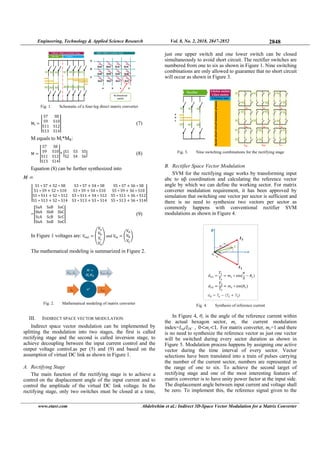
Fig. 9. M
A Simulink
lidate the effe
rying types o
ccessfully va
rious scenario
he input and
eration. The s
own in Table
-26.
ng, Technology
r.com
rdination and
rs [9] as per (1
d d
V
V
V
cles can be furt
∗
V
V
V
duty cycle mat
ctor, (V1 V2 V3
s the duty cy
dent on the sel
depending
matrix calcula
ence between
ks the prism a
es of S.
IV. MATR
ng stage is de
1 to 6, these n
switches and
x). At the sam
ating another
current active
(inverter
in (5) allows u
r. The procedu
Matrix converter
V. SIMUL
k simulation
ectiveness of m
f loads. The
alidated as w
os such as bala
output wavef
simulation was
I. The simula
y & Applied Sci
then is divid
2).
ther calculated
trix [8-10], (V
3)T
is the curren
ycle for each s
lected switchin
on each se
ations have b
prisms and te
and tetrahedron
RIX CONVERTE
edicated to gen
numbers repre
d would be re
me time the in
series of num
e inverter swit
matrix) as we
us to find all p
ure is shown in
code generation f
LINK SIMULATI
was successf
matrix conver
proposed indi
well. Simulati
anced and unb
forms ensured
s carried out u
ation results ar
ience Research
A
ed by the ava
(12
d as shown in
(13
(14
Vα-ref Vβ-ref Vδ-r
nt switching v
switching vec
ng vectors, so
elected prism
been done for
etrahedrons. Th
n number to e
ER
nerating a ser
esenting the c
epresented on
nversion stage
mbers from 1
tches that wou
ell. Multiplyin
possible switch
n Figure 9.
from Mi and MR
ION
fully develop
rter operation
irect 3D SVM
ion worked
balanced linear
d proper con
using the param
re shown in F
h V
Abdelrehim et a
ailable
2)
(13).
3)
4)
ref)T
is
vector,
ctor. S
it has
m and
r each
he 3D
extract
ries of
current
n
e is in
to 16,
uld be
ng the
hes for
ed to
under
M was
under
r load.
nverter
meters
igures
R
A.
Vol. 8, No. 2, 20
al.: Indirect 3D
Source sys
Load syst
Switching freq
Input filter
Output filter
Repetitive Contr
Tracking con
Unbalanced
Balanced l
Nonlinear l
Non-Linear L
Fig. 12. FF
018, 2847-2852
D-Space Vector M
TABLE I.
tem
em
quency
(LC)
r (LC)
roller Q(z)
ntroller
d load 5Ω
load
load
Load
Fig. 10. O
(a) P
(b) P
(c) P
(d) N
Fig. 11. O
FT analysis for ou
2
Modulation for
SYSTEM PARAM
440V
115V-
1280
56Ω/0.8m
180uH+70
1.72377
1.663
1.868
Ω+5.5mH, 10Ω+6
5Ω +5
3phase diode
Output voltage
Phase A
Phase B
Phase C
Neutral
Output current
utput phase voltag
2850
r a Matrix Con
METERS
V-60Hz
-400Hz
00Hz
mH/10uF
0uH/100uF
2 1
76 0.75754
3 0.9914
8 0.8735
6.2mH, 20Ω+7.5m
5.5 mH
e bridge +50Ω
ge (THD=3.3%)
verter
mH](https://image.slidesharecdn.com/2007-5061-1-pb-180517050056/85/Indirect-3D-Space-Vector-Modulation-for-a-Matrix-Converter-4-320.jpg)

![mo
bee
con
lim
(11
con
eff
rep
vo
[1]
[2]
[3]
[4]
[5]
[6]
[7]
Engineerin
www.etasr
Fig
Fig. 25. Inp
This paper
odulation for
en implement
ntroller was s
mited bandw
15V/400Hz).
nditions (bal
fectiveness o
petitive contro
ltage in an exc
P. Zanchetta,
Empringham, “
AC power s
Electronics Sp
16, 2005
C. Klumpner,
process of th
Electronics Sp
1083–1088, Ju
D. Casadei, G
torque control
Electronics, Vo
F. Yue, P. W. W
space vector m
Electronics Co
R. Zhang, Hig
unbalanced loa
State Universit
R. Cárdenasa,
control system
Electric Power
T. Friedli, J.
evaluation of t
back-to-back
Electronics, Vo
ng, Technology
r.com
Fig. 23.
. 24. Repetitive
put current multip
VI. C
introduced th
four-leg matri
ted and simu
selected to reg
width for
The simulat
anced, unbal
f the propos
oller showed t
cellent way.
REFE
J. C. Clare, P.
“Control Design
upply using ge
pecialists Confere
F. Blaabjerg, P
he matrix conve
ecialist Conferenc
une 17-21, 2001
G. Serra, A. Tani,
of induction mac
ol. 48, No. 6, pp.
Wheeler, N. Mas
modulation for a
onference, PESC 2
gh performance p
ad/source, PhD T
ty, 1998
R. Penab, J. Clar
m for four-leg mat
r Systems Researc
W. Kolar, J. Ro
three-phase AC–A
converter system
ol. 59, No. 12, pp
y & Applied Sci
Output current
e controller outpu
plied by factor 50
CONCLUSION
he design of
ix converter, c
ulated in Sim
gulate the out
high-freque
tion results
lanced, nonlin
sed modulati
the ability to
ERENCES
W. Wheeler, D
of a three-phase
enetic algorithms
ence, Recife, Braz
P. Nielsen, “Spee
erter technology
ce PESC, Vancou
“The use of ma
chines”, IEEE Tr
1057–1064, 2001
on, L. Empringha
a 4-leg matrix c
2007, Orlando, U
ower converter s
Thesis, Virginia P
e, P. Wheeler, P.
trix converters fe
ch, Vol. 104, pp.
odriguez, P. W.
AC matrix conver
ms”, IEEE Tran
p. 4487–4510, 201
ience Research
A
ut signal
and input voltage
3D SVM in
code validatio
mulink. A repe
tput voltage d
ency applic
for varying
near) ensured
ion technique
regulate the o
D. Katsis, M. Bla
matrix converter
s”, IEEE 36th
zil, pp. 2370-237
eding-up the mat
y”, 32nd IEEE
uver, Canada, Vol
atrix converters in
ransactions on In
1
am, J. C. Clare, “I
converter”, IEEE
USA, June 17-21, 2
ystem for nonlin
Polytechnic Institu
Zanchetta, “A rep
eding non-linear
18-27, 2013
Wheeler, “Comp
rter and voltage D
nsactions on In
12
h V
Abdelrehim et a
e
ndirect
on has
etitive
due to
cations
load
d the
e and
output
and, L.
mobile
Power
75, June
turation
Power
l. 2, pp.
n direct
dustrial
Indirect
Power
2007
ear and
ute and
petitive
loads”,
parative
DC-link
dustrial
[8]
[9]
[10]
[11]
[12]
[13]
[14]
[15]
[16]
[17]
[18]
[19]
[20]
[21]
[22]
[23]
Vol. 8, No. 2, 20
al.: Indirect 3D
V. H. Prasad, D
space vector mo
12th Annual A
(APEC), Atlant
R. Zhang, V. H
space vector m
Transanctions o
] R. Zhang, D B
Dubovsky, “A
modulation”, 1
Exposition, Atla
] L. Empringham
matrix convert
techniques”, 2
Conference, Vo
] J. Mahlein, J. Ig
commutation s
measurement”,
No. 2, pp. 407-4
] W. Hofmann, M
for matrix conv
24-32, 2003
] B. H. Kwon, B
AC-AC convert
145, No. 4, pp.
] P. W. Wheeler,
“Matrix conve
Industrial Electr
] E. Ormaetxea,
Alegria, E. Iba
computational
FPGA”, IEEE
272–287, 2011
] D. Casadei, G.
Przeglad Elektr
] L. Empringham
current comm
International Po
Czech Republic
] M. Ziegler, W
matrix convert
Electronics and
2001
] M. Ziegler, W.
cost matrix c
Nürnberg, Germ
] M. Ziegler, W.
for matrix conv
Conference (PE
] D. Casadei, A
commutation st
measurement”,
Applications (E
] L. Empringham
Wheeler, J. C.
aerospace ap
Compatibility a
451–456, 2011
018, 2847-2852
D-Space Vector M
D. Boroyevich, R
odulation scheme
Applied Power E
ta, USA, Vol. 2, p
H. Prasad, D. Bor
modulation for fou
on Power Electron
Boroyevich, V. H
three-phase inver
2th Annual App
anta, USA, Vol. 2
m, P. W. Wheeler,
ter bi-directional
29th Annual I
ol. 1, pp. 707-713
gney, J. Weigold,
strategies with an
IEEE Transactio
414, 2002
M. Ziegler, “Mult
verters”, Journal o
B. D. Min, J. H. K
ters”, IEE Procee
295–300, 1998
J. Rodriguez, J.
erters: a technol
ronics, Vol. 49, N
J. Andreu, I. K
arra, E. Olaguen
capabilities based
Transactions on
Serra, A. Tani, L.
rotechniczny, Vol
m, P. W. Wheel
mutation for m
ower Electronics
c, pp. 42–47, Sept
W. Hofmann, “Ne
ters”, 4th IEEE
d Drive Systems,
Hofmann, “A new
converters”, 41s
many, pp. 445-450
Hofmann, “Semi
verters”, 29th Ann
ESC’98), Fukuoka
. Trentin, M. M
trategy using bot
European Con
EPE’03), Toulouse
m L, L. de Lill
Clare, “Enabling
pplications”, In
and Power Electr
2
Modulation for
R. Zhang, “Analy
es for a four-leg v
Electronics Conf
pp. 864-871, Febr
royevich, F. C. L
ur-leg voltage- so
nics, Vol. 17, No.
H. Prasad, H. C
rter with a neutra
lied Power Elect
2, pp. 857-863, Fe
, J. C. Clare, “Inte
l switch cells u
IEEE Power E
, May 22, 1998
, M. Braun, O. Sim
nd without expli
ons on Industria
ti-step commutati
of Power Electro
Kim, “Novel com
edings-Electric Po
C. Clare, L. Emp
logy review”, I
No. 2, pp. 276–28
Kortabarria, U. B
naga, “Matrix co
d on a system o
Power Electronic
. Zarri, “A review
l. 82, No. 2, pp. 15
ler, J. C. Clare,
matrix converte
& Motion Contr
tember 8-10, 1998
ew one-step com
E International C
, Bali, Indonesia
w two steps comm
st PCIM/Power
0, 2000
i natural two step
nual IEEE Power
a, Japan, pp. 727–
Matteini, M. Calv
th output current
nference on Po
e, France, pp. P1–
lo, S. Khwan-On
g technologies fo
nternational Co
ronics (CPE’2011
2852
r a Matrix Con
ysis and compari
voltage source inv
ference and Expo
ruary 27, 1997
Lee, “Three-dimen
ource converters”,
. 3, pp. 314-326, 2
C. Mao, F. C. L
al leg with space
tronics Conferenc
ebruary 27, 1997
elligent commuta
using novel gate
Electronics Spec
mon, “Matrix con
icit input voltag
al Electronics, Vo
ion and control p
nics, Vol. 3, No.
mmutation techni
ower Application
pringham, A. Wei
IEEE Transactio
8, 2002
Bidarte, I. Martin
onverter protectio
on chip design w
cs, Vol. 26, No.
w on matrix conve
5–25, 2006
“Bi-directional
er applications”
rol Conference, P
8
mmutation strateg
Conference on
, Vol. 2, pp. 560
mutation policy f
Quality Confe
ps commutation st
r Electronics Spec
–731, May 22, 19
vini, “Matrix con
and input voltag
ower Electronics
–P10, 2003
n, C. Brunson,
or matrix conver
onference Wor
1), Tallinn, Eston
verter
ison of
verter”,
osition
nsional
, IEEE
2002
Lee, S.
vector
ce and
ation of
drive
cialists
nverter
ge sign
ol. 49,
policies
1, pp.
que of
s, Vol.
nstejn,
ons on
nez de
on and
with an
1, pp.
erters”,
switch
, 8th
Prague,
gies in
Power
0–564,
for low
erence,
trategy
cialists
98
nverter
ge sign
s and
P. W.
rters in
rkshop
nia, pp.](https://image.slidesharecdn.com/2007-5061-1-pb-180517050056/85/Indirect-3D-Space-Vector-Modulation-for-a-Matrix-Converter-6-320.jpg)

This paper presents a novel indirect space vector modulation (SVM) technique for a four-leg matrix converter, aimed at improving control over unbalanced or nonlinear loads. The proposed method simplifies modulation processes for digital controllers and allows for effective regulation in high-frequency applications. Simulations conducted using a repetitive controller demonstrated the effectiveness of this technique for managing output voltages in 400 Hz power supply systems.


![[IJET-V1I6P7] Authors: Galal Ali Hassaan](https://cdn.slidesharecdn.com/ss_thumbnails/ijet-v1i6p7-151213092439-thumbnail.jpg?width=640&height=640&fit=bounds)