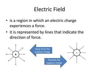
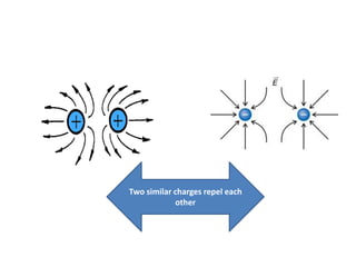
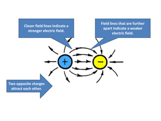
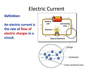
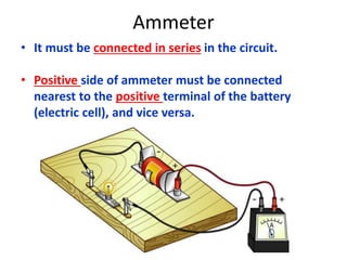
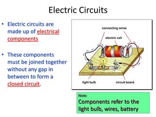
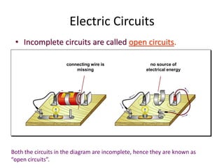
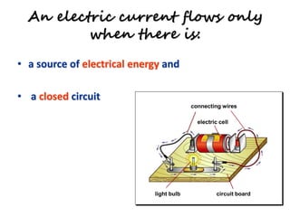
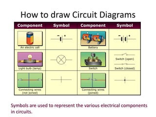
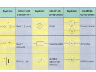
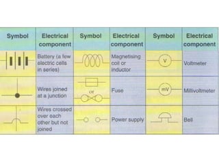
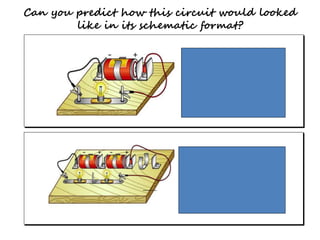
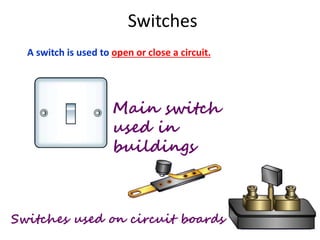
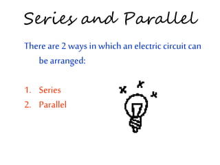
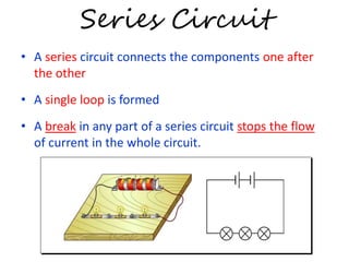
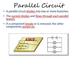
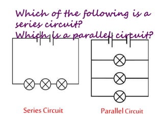
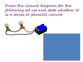
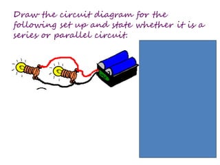
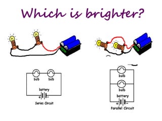
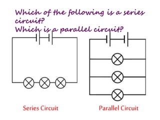
Electric Field, Electric Current 
and Electrical Circuit
Electric Field 
• is a region in which an electric charge 
experiences a force. 
• it is represented by lines that indicate the 
direction of force. 
+ 
Away from the 
positive charge - 
Towards the 
negative charge
Two similar charges repel each 
other
Closer field lines indicate a 
stronger electric field. 
Field lines that are further 
apart indicate a weaker 
electric field. 
Two opposite charges 
attract each other.
Electric Current 
connecting 
wire 
electric 
cell 
filament 
flow of electrons 
Charge 
Conductor 
Cross-sectional area 
Definition: 
An electric current is 
the rate of flow of 
electric charges in a 
circuit.
How does electricity flow? 
• The battery in a circuit gives energy to the 
electrons and pushes them around a circuit, 
from the negative terminal of the cell, round 
the circuit and back to the positive terminal 
of the cell.
How to Measure Current? 
• The SI unit for electric current is ampere (A). 
• Smaller currents are measured in milliamperes 
(mA). 
1 A = 1,000 mA 
1 mA = 0.001 A 
• Different electrical components and appliances 
require different sizes of current to turn them on.
Instrument to Measure Current 
• An ammeter is an instrument used for 
measuring electric current.
Ammeter 
• It must be connected in series in the circuit. 
• Positive side of ammeter must be connected 
nearest to the positive terminal of the battery 
(electric cell), and vice versa.
Electric Circuits 
• Electric circuits are 
made up of electrical 
components 
• These components 
must be joined together 
without any gap in 
between to form a 
closed circuit. 
connecting wires 
electric cell 
light bulb circuit board 
Note: 
Components refer to the 
light bulb, wires, battery
Electric Circuits 
• Incomplete circuits are called open circuits. 
connecting wire is 
missing 
no source of 
electrical energy 
Both the circuits in the diagram are incomplete, hence they are known as 
“open circuits”.
An electric current flows only 
when there is: 
• a source of electrical energy and 
• a closed circuit 
connecting wires 
electric cell 
light bulb circuit board
How to draw Circuit Diagrams 
Component Symbol Component Symbol 
+ + 
An electric cell Battery 
Light bulb (lamp) Switch 
Switch (open) 
Switch (closed) 
Connecting wires 
(not joined) 
Connecting wires 
(joined) 
Symbols are used to represent the various electrical components 
in circuits.
Can you predict how this circuit would looked 
like in its schematic format?
Switches 
A switch is used to open or close a circuit. 
Main switch 
used in 
buildings 
Switches used on circuit boards
Series and Parallel 
There are 2 ways in which an electric circuit can 
be arranged: 
1. Series 
2. Parallel
Series Circuit 
• A series circuit connects the components one after 
the other 
• A single loop is formed 
• A break in any part of a series circuit stops the flow 
of current in the whole circuit.
Parallel Circuit 
• A parallel circuit divides into two or more branches. 
• The current divides and flows through each parallel 
branch. 
• If a component breaks or is removed, the other 
components remain on.
Which of the following is a 
series circuit? 
Which is a parallel circuit? 
Series Circuit Parallel Circuit
Draw the circuit diagram for the 
following set up and state whether it 
is a series or parallel circuit.
Draw the circuit diagram for the 
following set up and state whether it is a 
series or parallel circuit.
Which is brighter?
Which of the following is a series 
circuit? 
Which is a parallel circuit? 
Series Circuit Parallel Circuit

STEM : ELECTRICITY INTRODUCTION

  • 1.
    Electric Field, ElectricCurrent and Electrical Circuit
  • 2.
    Electric Field •is a region in which an electric charge experiences a force. • it is represented by lines that indicate the direction of force. + Away from the positive charge - Towards the negative charge
  • 3.
    Two similar chargesrepel each other
  • 4.
    Closer field linesindicate a stronger electric field. Field lines that are further apart indicate a weaker electric field. Two opposite charges attract each other.
  • 5.
    Electric Current connecting wire electric cell filament flow of electrons Charge Conductor Cross-sectional area Definition: An electric current is the rate of flow of electric charges in a circuit.
  • 6.
    How does electricityflow? • The battery in a circuit gives energy to the electrons and pushes them around a circuit, from the negative terminal of the cell, round the circuit and back to the positive terminal of the cell.
  • 7.
    How to MeasureCurrent? • The SI unit for electric current is ampere (A). • Smaller currents are measured in milliamperes (mA). 1 A = 1,000 mA 1 mA = 0.001 A • Different electrical components and appliances require different sizes of current to turn them on.
  • 8.
    Instrument to MeasureCurrent • An ammeter is an instrument used for measuring electric current.
  • 9.
    Ammeter • Itmust be connected in series in the circuit. • Positive side of ammeter must be connected nearest to the positive terminal of the battery (electric cell), and vice versa.
  • 10.
    Electric Circuits •Electric circuits are made up of electrical components • These components must be joined together without any gap in between to form a closed circuit. connecting wires electric cell light bulb circuit board Note: Components refer to the light bulb, wires, battery
  • 11.
    Electric Circuits •Incomplete circuits are called open circuits. connecting wire is missing no source of electrical energy Both the circuits in the diagram are incomplete, hence they are known as “open circuits”.
  • 12.
    An electric currentflows only when there is: • a source of electrical energy and • a closed circuit connecting wires electric cell light bulb circuit board
  • 13.
    How to drawCircuit Diagrams Component Symbol Component Symbol + + An electric cell Battery Light bulb (lamp) Switch Switch (open) Switch (closed) Connecting wires (not joined) Connecting wires (joined) Symbols are used to represent the various electrical components in circuits.
  • 16.
    Can you predicthow this circuit would looked like in its schematic format?
  • 17.
    Switches A switchis used to open or close a circuit. Main switch used in buildings Switches used on circuit boards
  • 18.
    Series and Parallel There are 2 ways in which an electric circuit can be arranged: 1. Series 2. Parallel
  • 19.
    Series Circuit •A series circuit connects the components one after the other • A single loop is formed • A break in any part of a series circuit stops the flow of current in the whole circuit.
  • 20.
    Parallel Circuit •A parallel circuit divides into two or more branches. • The current divides and flows through each parallel branch. • If a component breaks or is removed, the other components remain on.
  • 21.
    Which of thefollowing is a series circuit? Which is a parallel circuit? Series Circuit Parallel Circuit
  • 22.
    Draw the circuitdiagram for the following set up and state whether it is a series or parallel circuit.
  • 23.
    Draw the circuitdiagram for the following set up and state whether it is a series or parallel circuit.
  • 24.
  • 25.
    Which of thefollowing is a series circuit? Which is a parallel circuit? Series Circuit Parallel Circuit