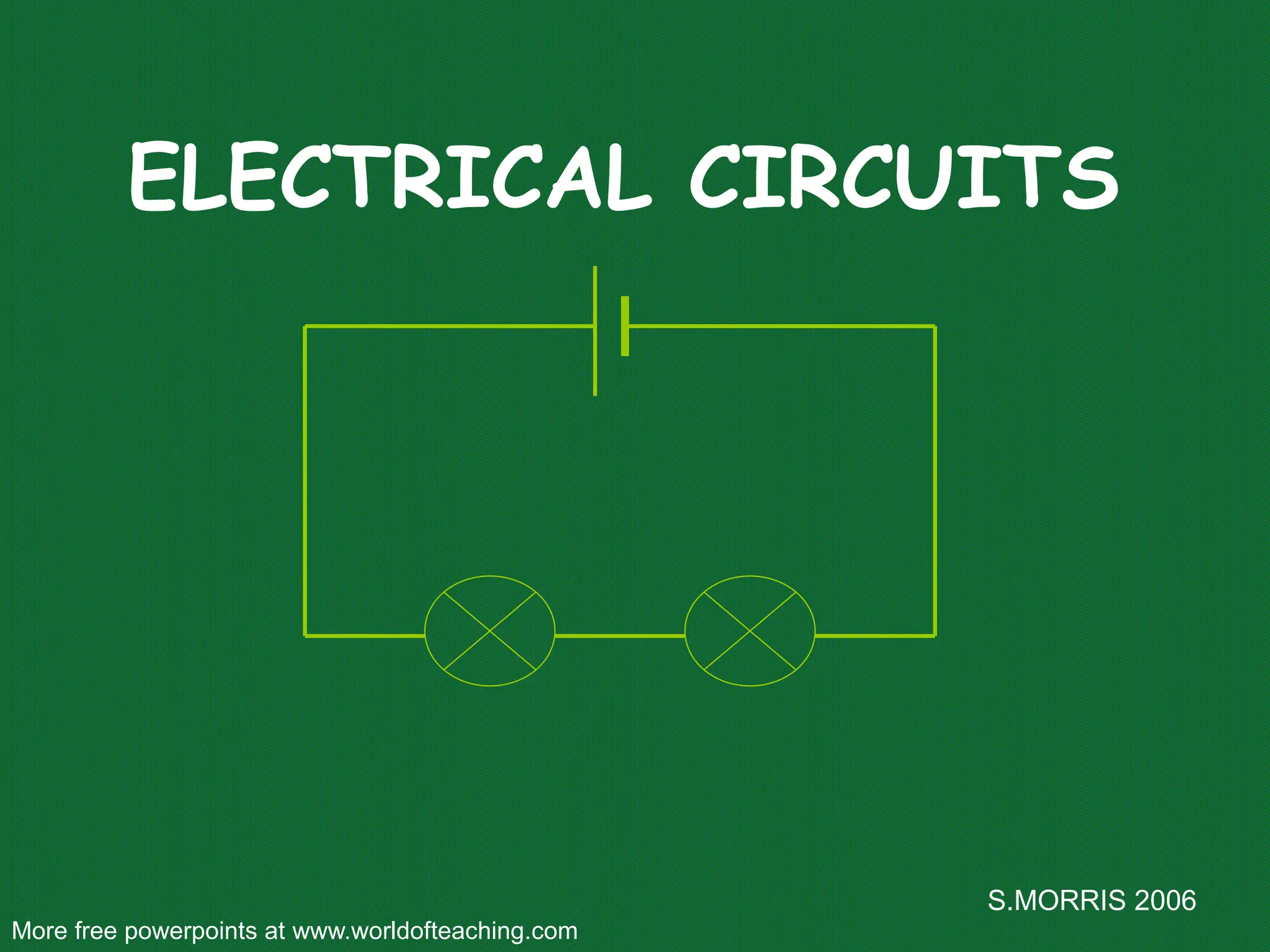
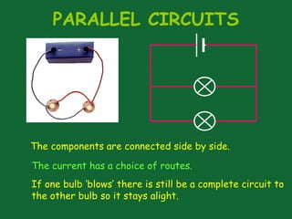
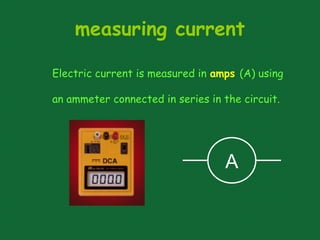
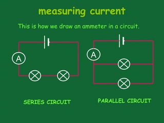
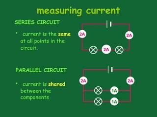
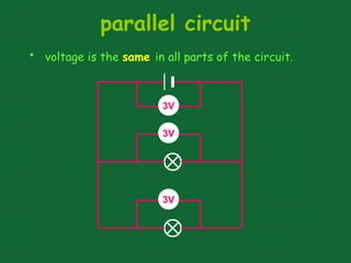
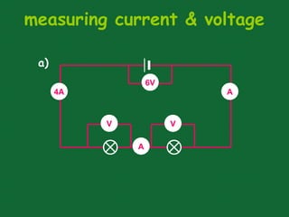
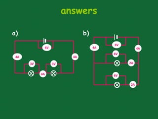
S.MORRIS 2006
ELECTRICAL CIRCUITS
More free powerpoints at www.worldofteaching.com
The CELL
The cell stores chemical energy and transfers it to
electrical energy when a circuit is connected.
When two or more cells are
connected together we call this
a Battery.
The cells chemical energy is
used up pushing a current round
a circuit.
What is an electric current?
An electric current is a flow of microscopic particles
called electrons flowing through wires and
components.
+
-
In which direction does the current flow?
from the Negative terminal to the Positive terminal of a
cell.
simple circuits
Here is a simple electric circuit. It has a cell, a
lamp and a switch.
To make the circuit, these components are connected
together with metal connecting wires.
cell
lamp
switch
wires
simple circuits
When the switch is closed, the lamp lights up. This is
because there is a continuous path of metal for the
electric current to flow around.
If there were any breaks in the circuit, the
current could not flow.
circuit diagram
cell switch
lamp wires
Scientists usually draw electric circuits using symbols;
circuit diagrams
In circuit diagrams components are represented by
the following symbols;
cell battery switch lamp
motor
ammeter voltmeter
buzzer
resistor variable
resistor
types of circuit
There are two types of electrical circuits;
SERIES CIRCUITS PARALLEL CIRCUITS
The components are connected end-to-end, one
after the other.
They make a simple loop for the current to flow
round.
SERIES CIRCUITS
If one bulb ‘blows’ it breaks the whole circuit and
all the bulbs go out.
PARALLEL CIRCUITS
The current has a choice of routes.
The components are connected side by side.
If one bulb ‘blows’ there is still be a complete circuit to
the other bulb so it stays alight.
measuring current
Electric current is measured in amps (A) using
an ammeter connected in series in the circuit.
A
measuring current
A A
This is how we draw an ammeter in a circuit.
SERIES CIRCUIT PARALLEL CIRCUIT
measuring current
SERIES CIRCUIT
PARALLEL CIRCUIT
• current is the same
at all points in the
circuit.
2A 2A
2A
• current is shared
between the
components
2A
2A
1A
1A
copy the following circuits and fill in the
missing ammeter readings.
?
?
4A
4A
4A
3A
?
?
1A
?
3A
1A
1A
measuring voltage
The ‘electrical push’ which the cell gives to the current
is called the voltage. It is measured in volts (V) on a
voltmeter
V
Different cells produce different voltages. The
bigger the voltage supplied by the cell, the bigger the
current.
measuring voltage
Unlike an ammeter a voltmeter is connected across
the components
Scientist usually use the term Potential Difference
(pd) when they talk about voltage.
measuring voltage
V
This is how we draw a voltmeter in a circuit.
SERIES CIRCUIT PARALLEL CIRCUIT
V
V
measuring voltage
V
V
V
series circuit
1.5V
• voltage is shared between the components
1.5V
3V
• voltage is the same in all parts of the circuit.
3V
parallel circuit
3V
3V
measuring current & voltage
copy the following circuits on the next two
slides.
complete the missing current and voltage
readings.
remember the rules for current and voltage
in series and parallel circuits.
measuring current & voltage
V V
6V
4A
A
A
a)
measuring current & voltage
V
V
6V
4A A
A
A
b)
answers
3V 3V
6V
4A 4A
6V
6V
6V
4A 4A
2A
2A
4A
a) b)

Electric-circuits.pptx science and biology

  • 1.
    S.MORRIS 2006 ELECTRICAL CIRCUITS Morefree powerpoints at www.worldofteaching.com
  • 2.
    The CELL The cellstores chemical energy and transfers it to electrical energy when a circuit is connected. When two or more cells are connected together we call this a Battery. The cells chemical energy is used up pushing a current round a circuit.
  • 3.
    What is anelectric current? An electric current is a flow of microscopic particles called electrons flowing through wires and components. + - In which direction does the current flow? from the Negative terminal to the Positive terminal of a cell.
  • 4.
    simple circuits Here isa simple electric circuit. It has a cell, a lamp and a switch. To make the circuit, these components are connected together with metal connecting wires. cell lamp switch wires
  • 5.
    simple circuits When theswitch is closed, the lamp lights up. This is because there is a continuous path of metal for the electric current to flow around. If there were any breaks in the circuit, the current could not flow.
  • 6.
    circuit diagram cell switch lampwires Scientists usually draw electric circuits using symbols;
  • 7.
    circuit diagrams In circuitdiagrams components are represented by the following symbols; cell battery switch lamp motor ammeter voltmeter buzzer resistor variable resistor
  • 8.
    types of circuit Thereare two types of electrical circuits; SERIES CIRCUITS PARALLEL CIRCUITS
  • 9.
    The components areconnected end-to-end, one after the other. They make a simple loop for the current to flow round. SERIES CIRCUITS If one bulb ‘blows’ it breaks the whole circuit and all the bulbs go out.
  • 10.
    PARALLEL CIRCUITS The currenthas a choice of routes. The components are connected side by side. If one bulb ‘blows’ there is still be a complete circuit to the other bulb so it stays alight.
  • 11.
    measuring current Electric currentis measured in amps (A) using an ammeter connected in series in the circuit. A
  • 12.
    measuring current A A Thisis how we draw an ammeter in a circuit. SERIES CIRCUIT PARALLEL CIRCUIT
  • 13.
    measuring current SERIES CIRCUIT PARALLELCIRCUIT • current is the same at all points in the circuit. 2A 2A 2A • current is shared between the components 2A 2A 1A 1A
  • 14.
    copy the followingcircuits and fill in the missing ammeter readings. ? ? 4A 4A 4A 3A ? ? 1A ? 3A 1A 1A
  • 15.
    measuring voltage The ‘electricalpush’ which the cell gives to the current is called the voltage. It is measured in volts (V) on a voltmeter V
  • 16.
    Different cells producedifferent voltages. The bigger the voltage supplied by the cell, the bigger the current. measuring voltage Unlike an ammeter a voltmeter is connected across the components Scientist usually use the term Potential Difference (pd) when they talk about voltage.
  • 17.
    measuring voltage V This ishow we draw a voltmeter in a circuit. SERIES CIRCUIT PARALLEL CIRCUIT V
  • 18.
  • 19.
    series circuit 1.5V • voltageis shared between the components 1.5V 3V
  • 20.
    • voltage isthe same in all parts of the circuit. 3V parallel circuit 3V 3V
  • 21.
    measuring current &voltage copy the following circuits on the next two slides. complete the missing current and voltage readings. remember the rules for current and voltage in series and parallel circuits.
  • 22.
    measuring current &voltage V V 6V 4A A A a)
  • 23.
    measuring current &voltage V V 6V 4A A A A b)
  • 24.