This document provides an overview of electricity and electric circuits. It defines key terms like current, voltage, resistance and discusses concepts such as series and parallel circuits. The three main points covered are:
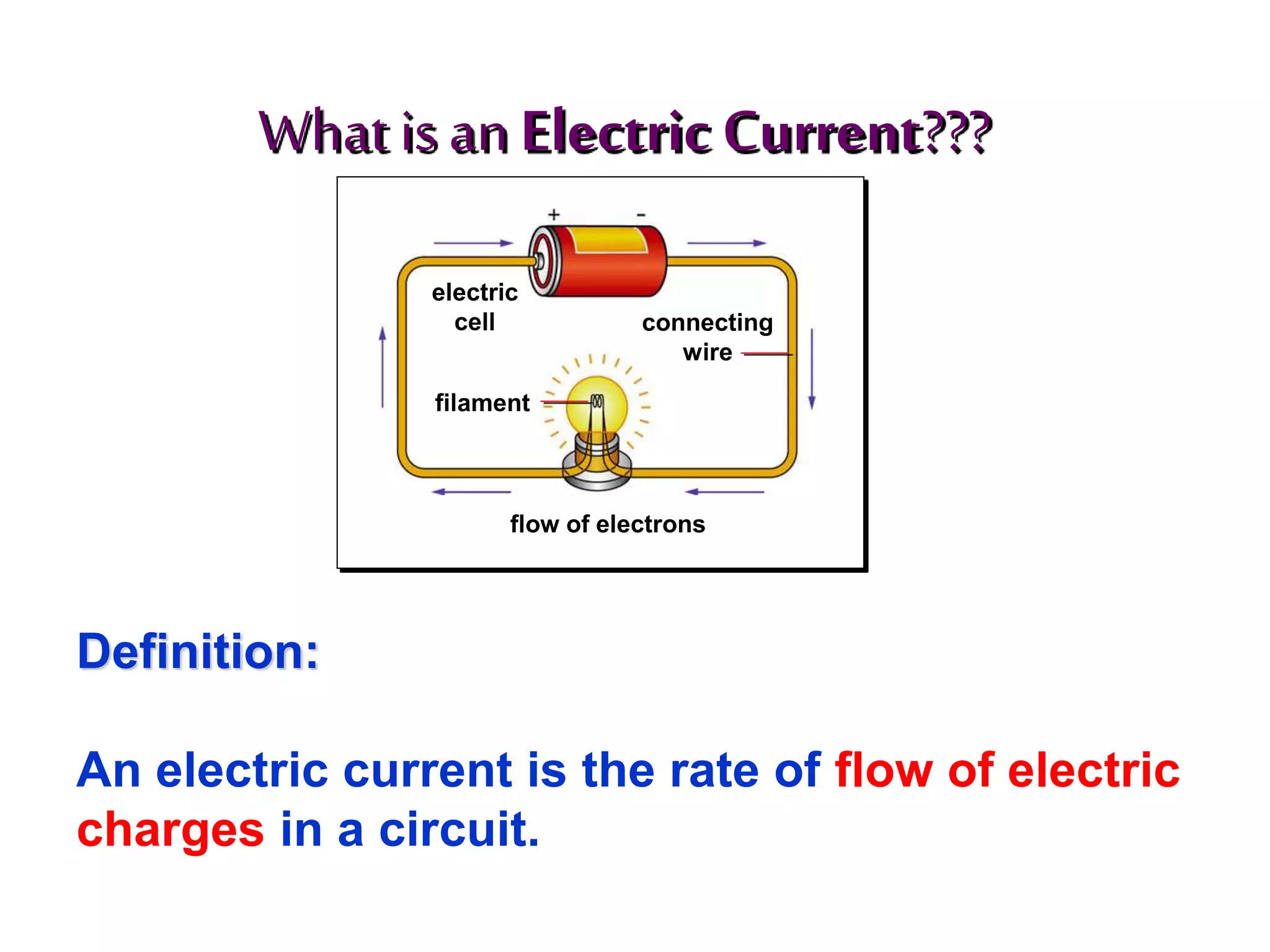
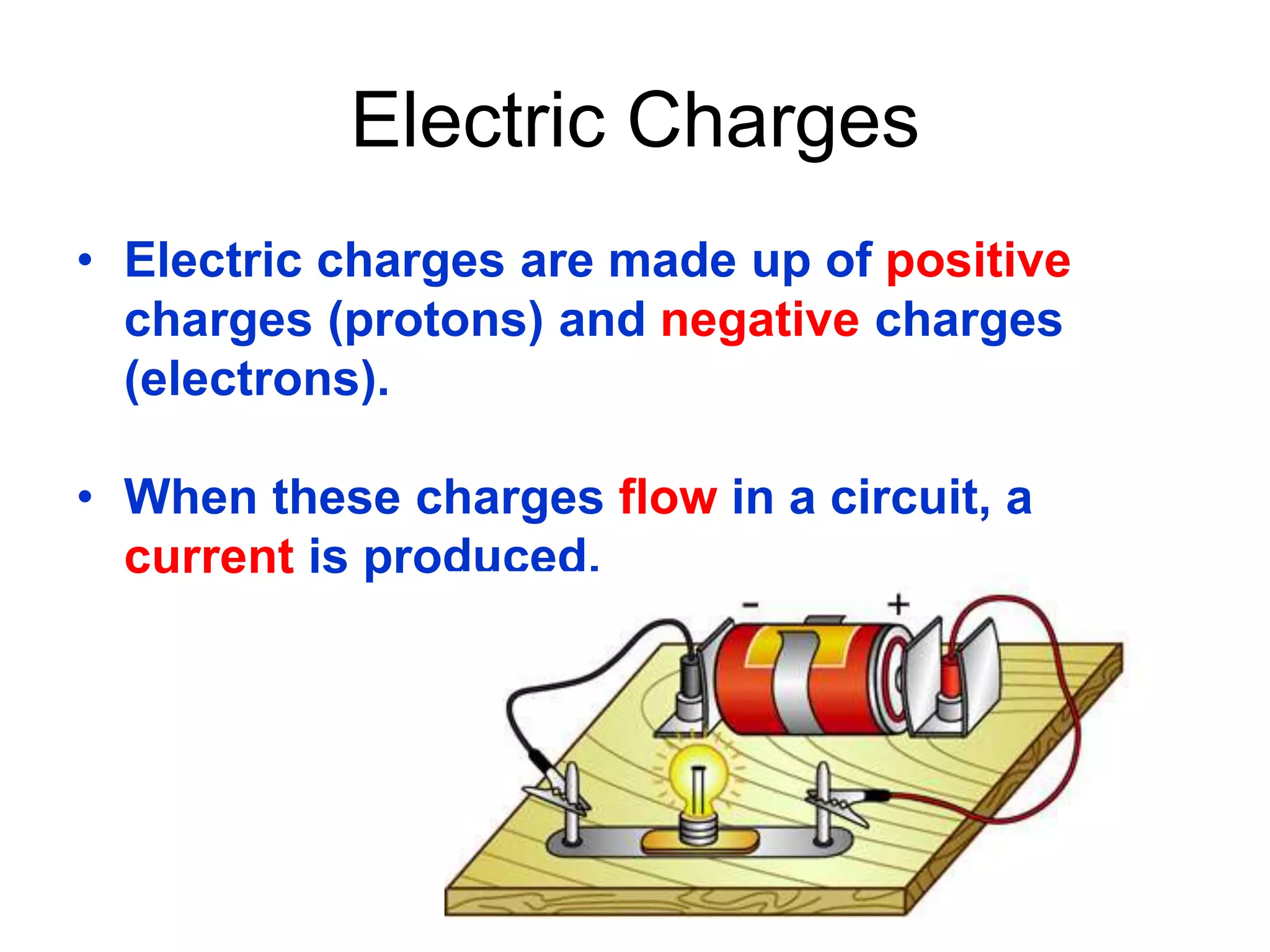
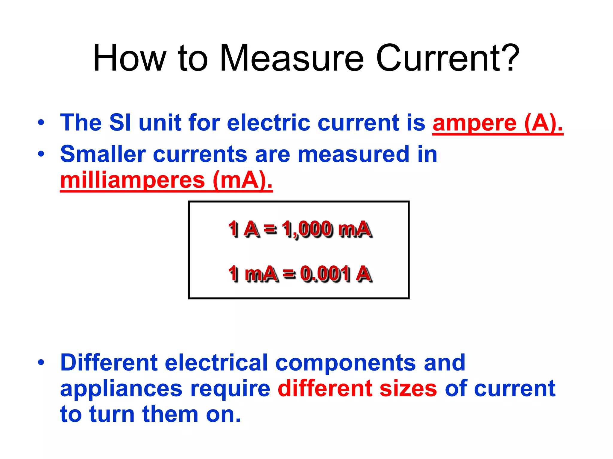
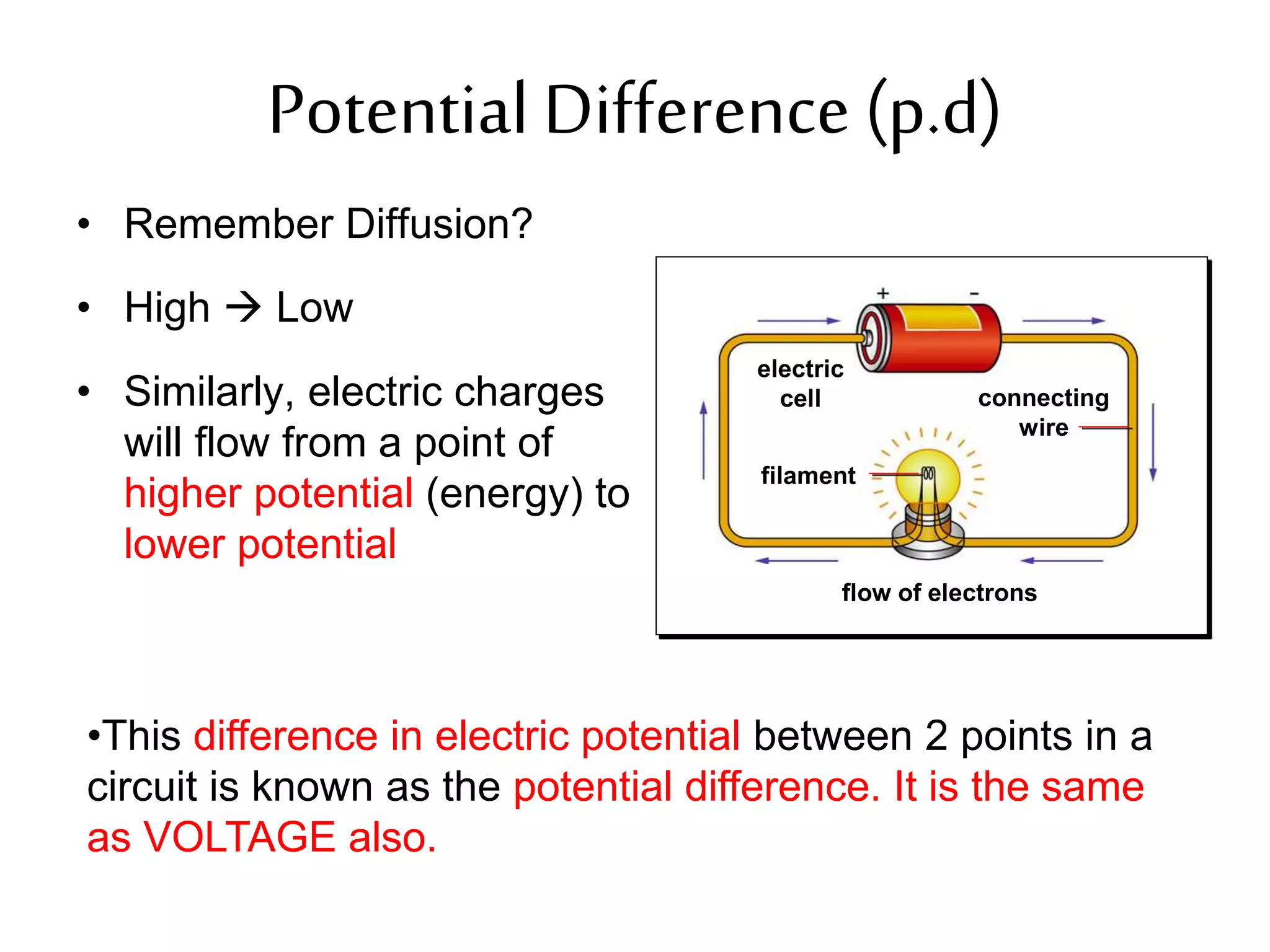
1. It defines electricity as a form of energy involving the flow of electrons in a circuit. Current is defined as the flow of electric charge.
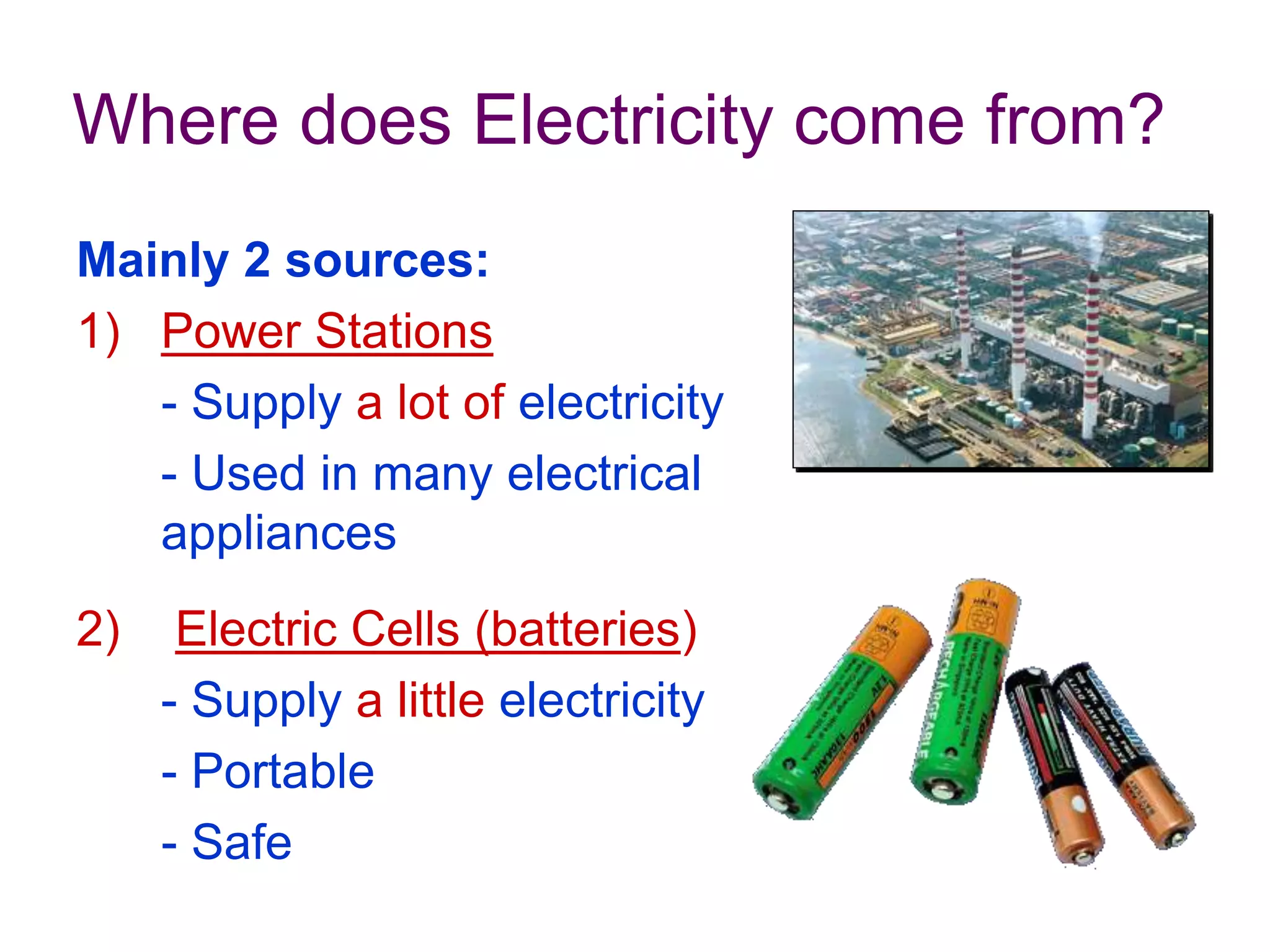
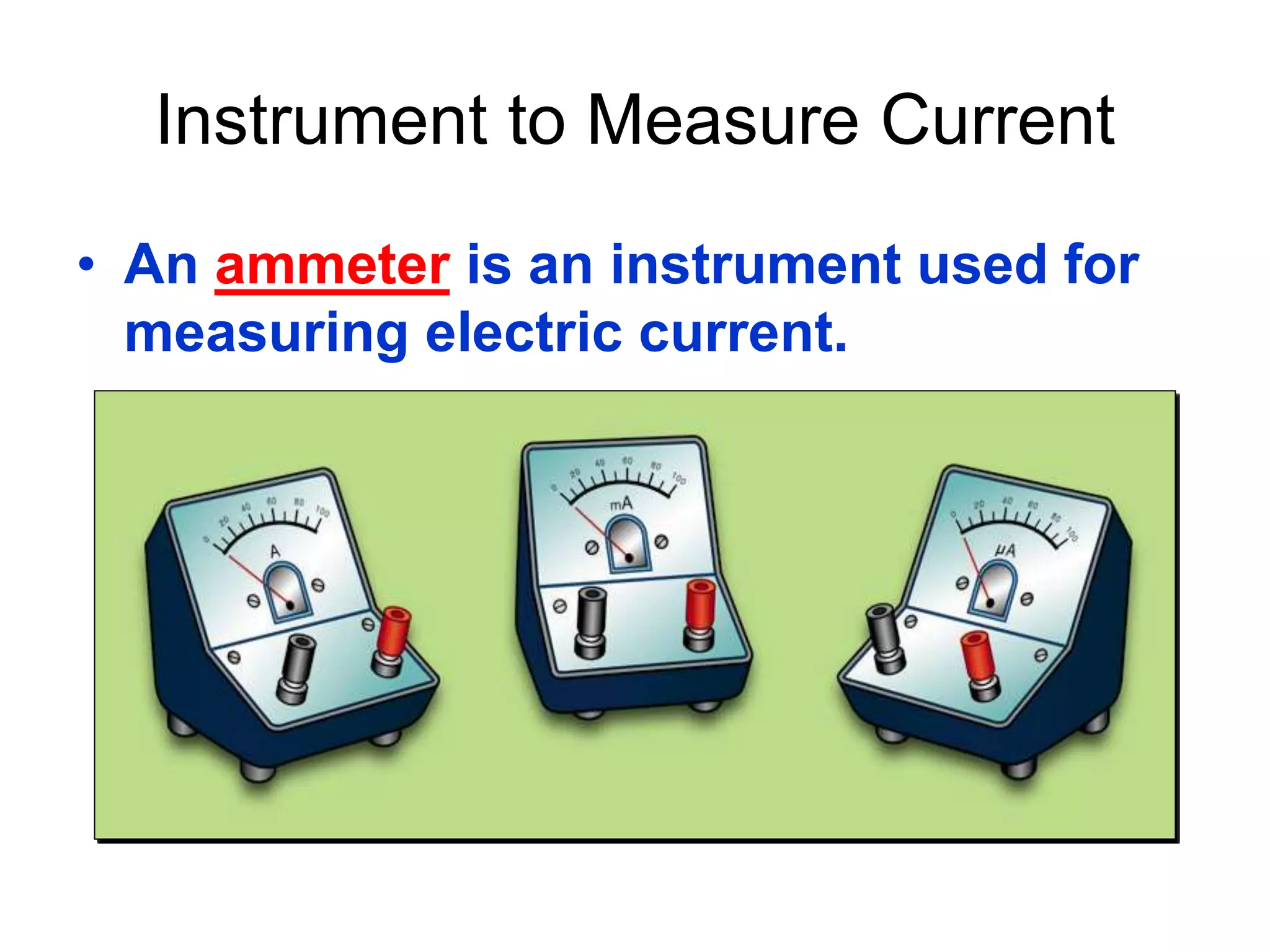
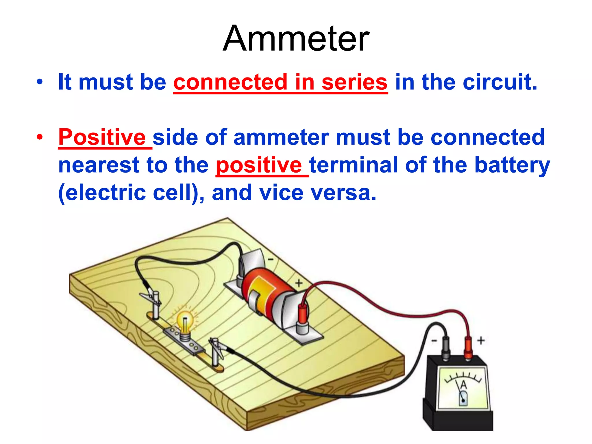
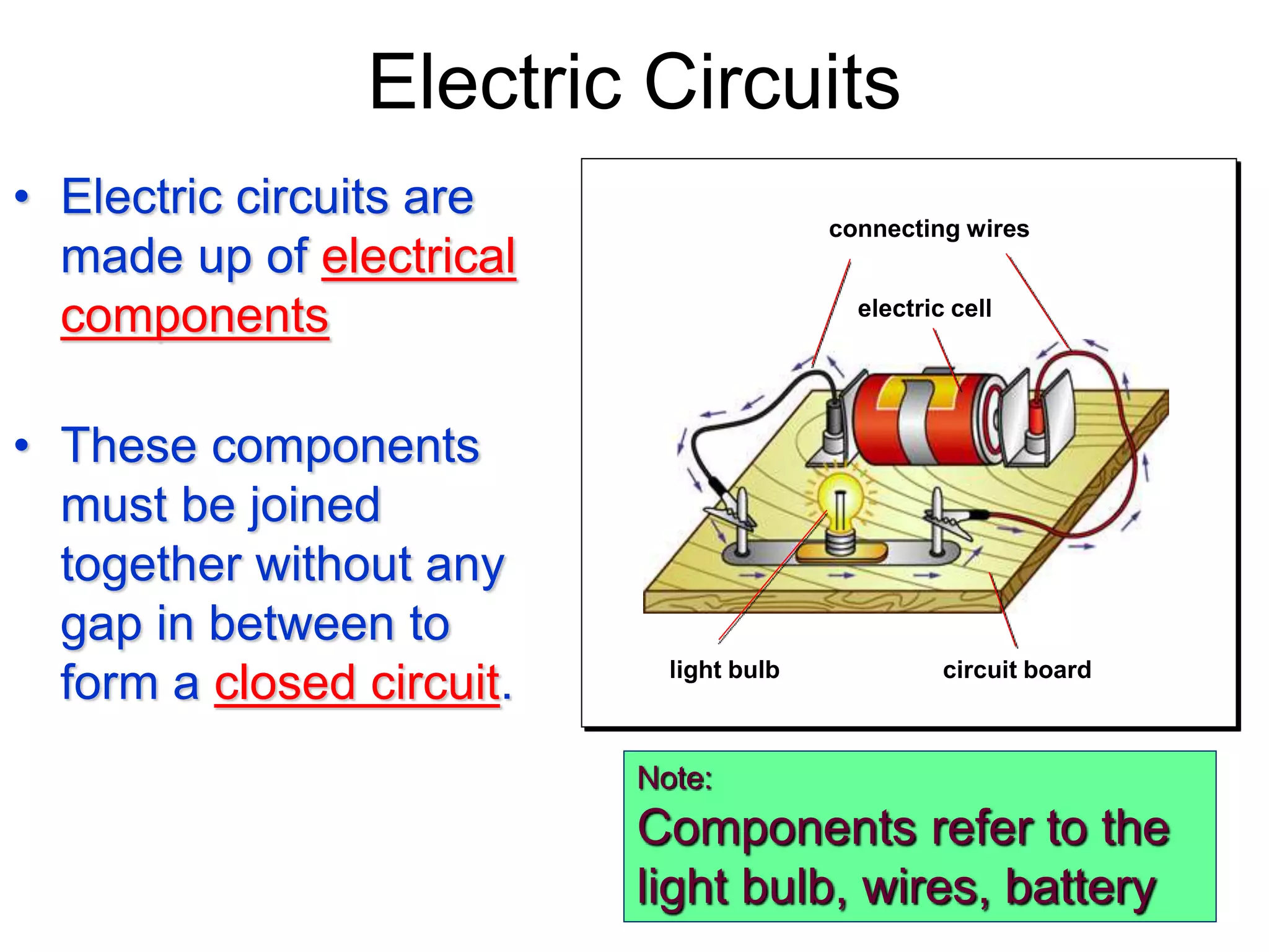
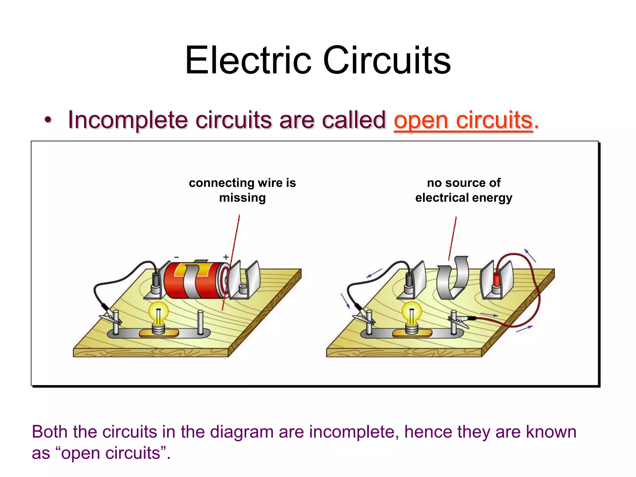
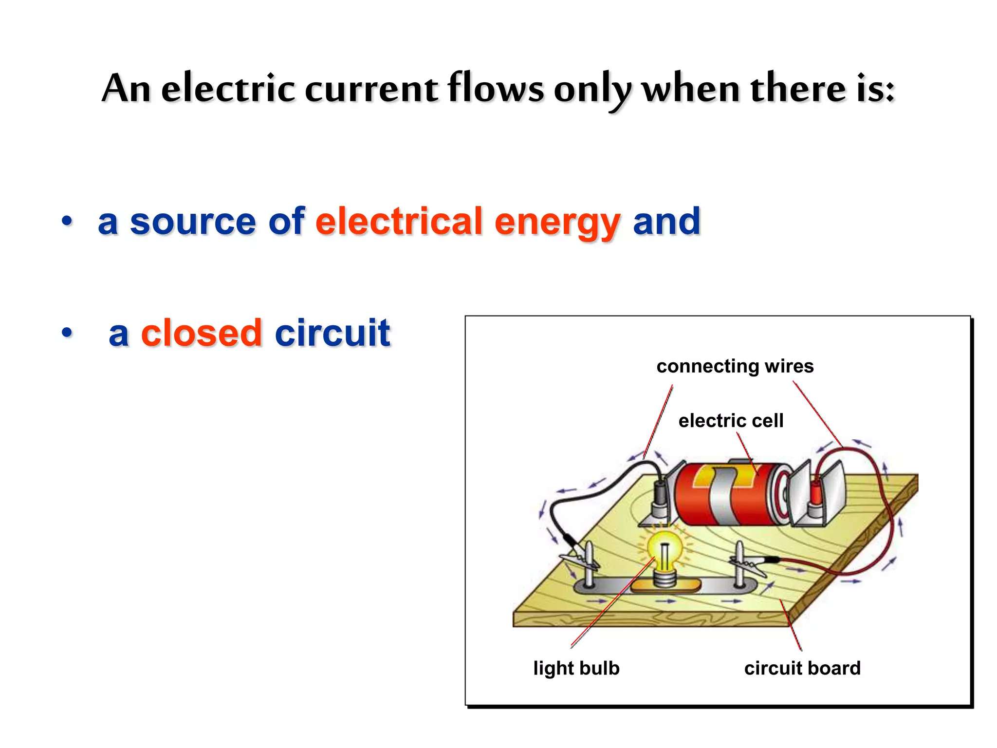
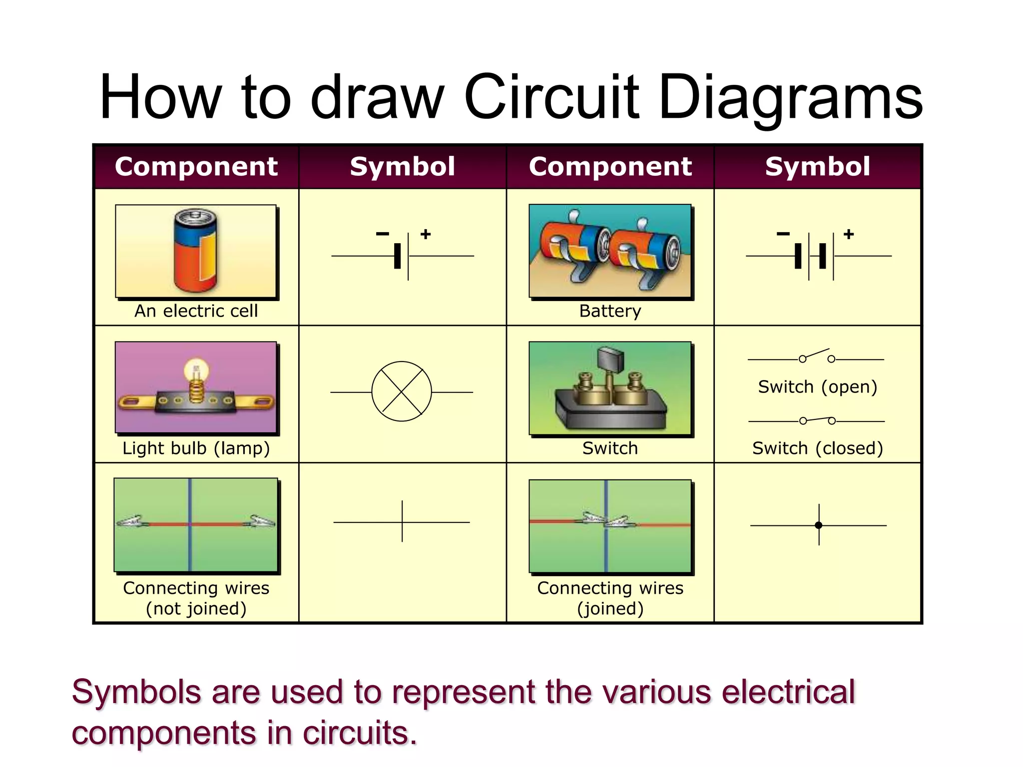
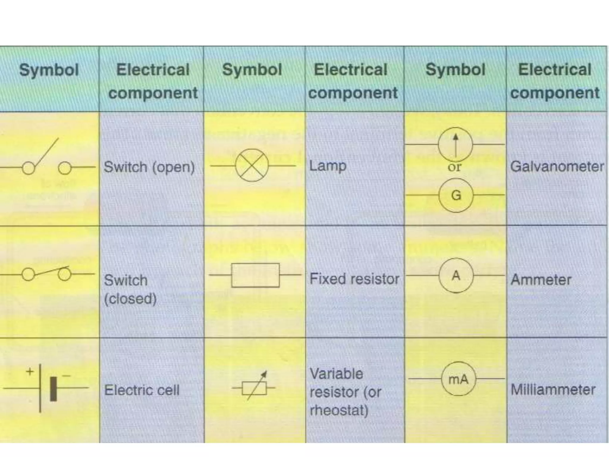
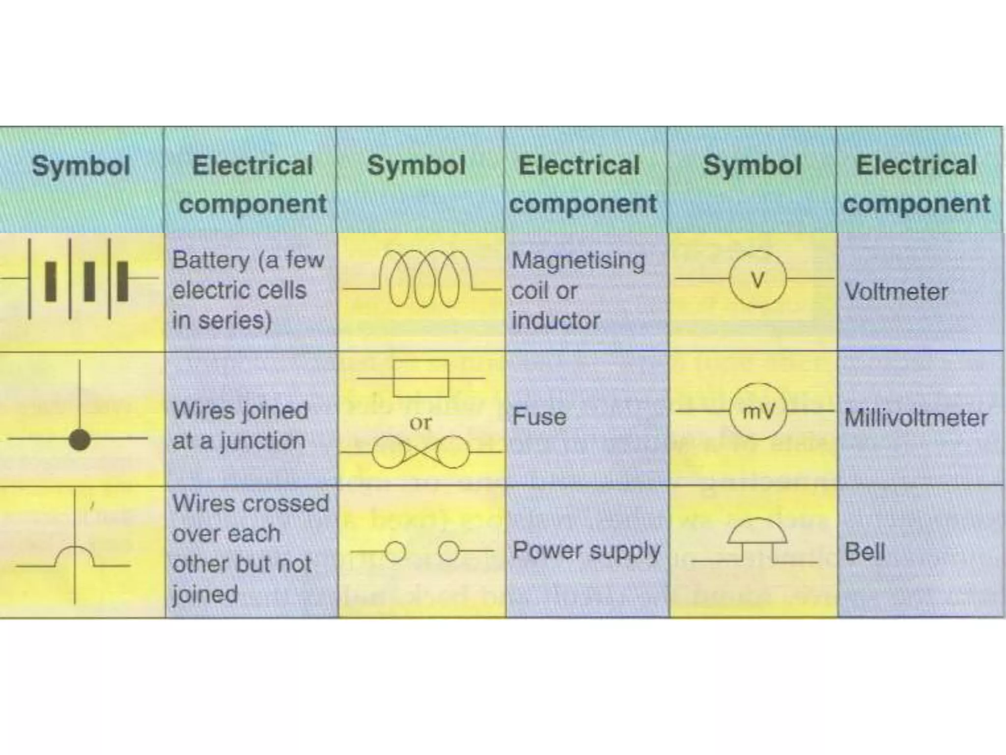
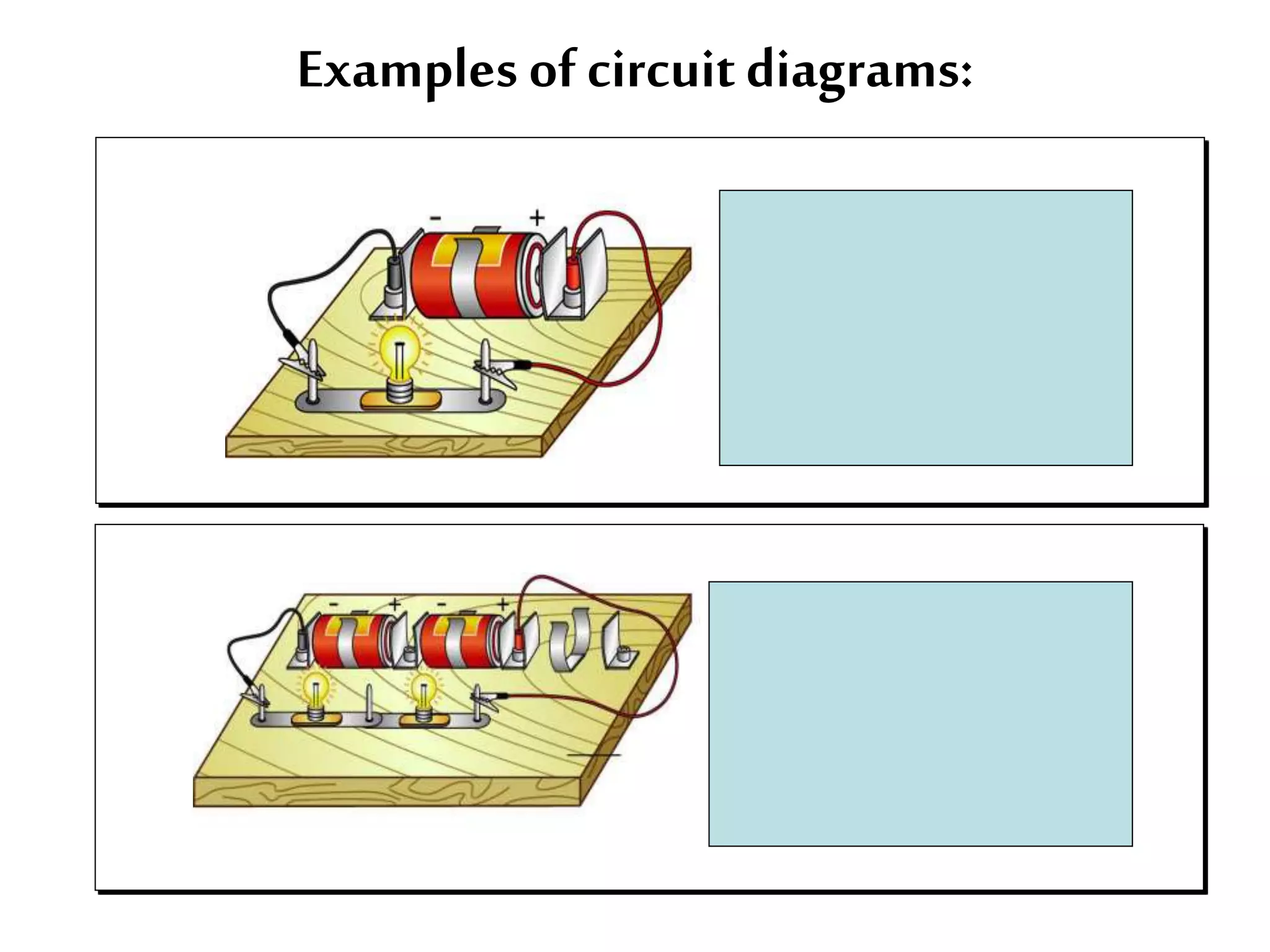
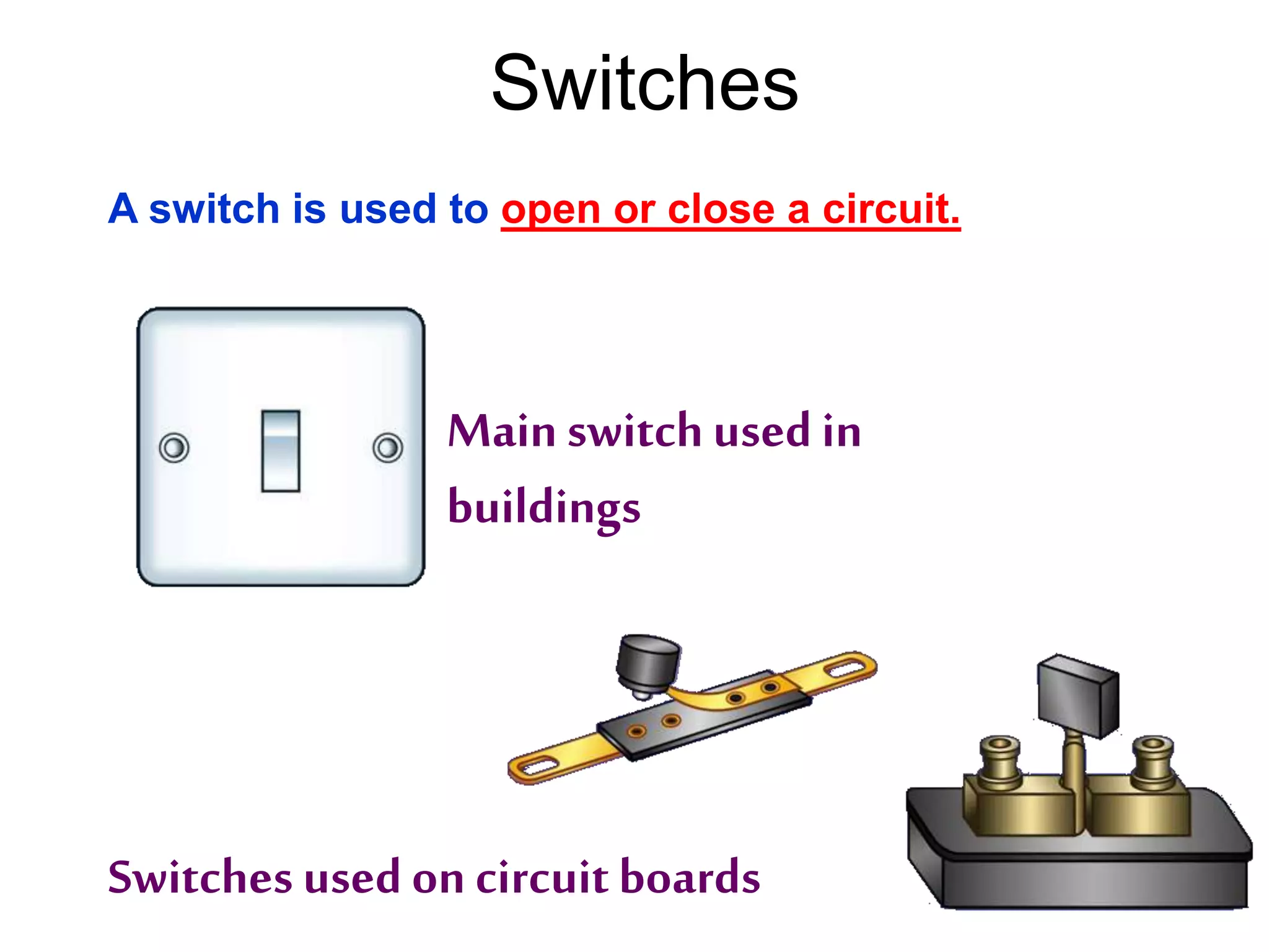
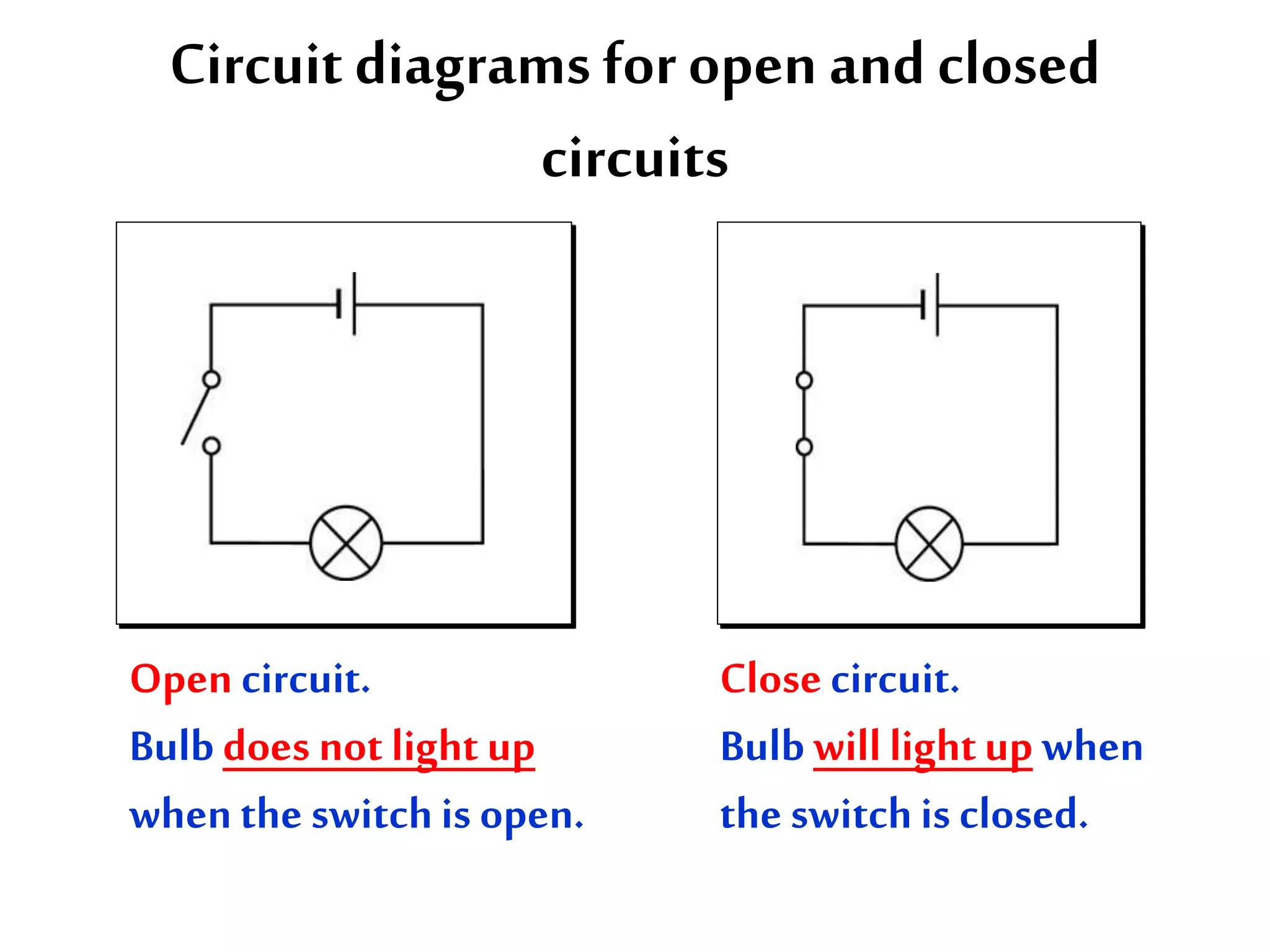
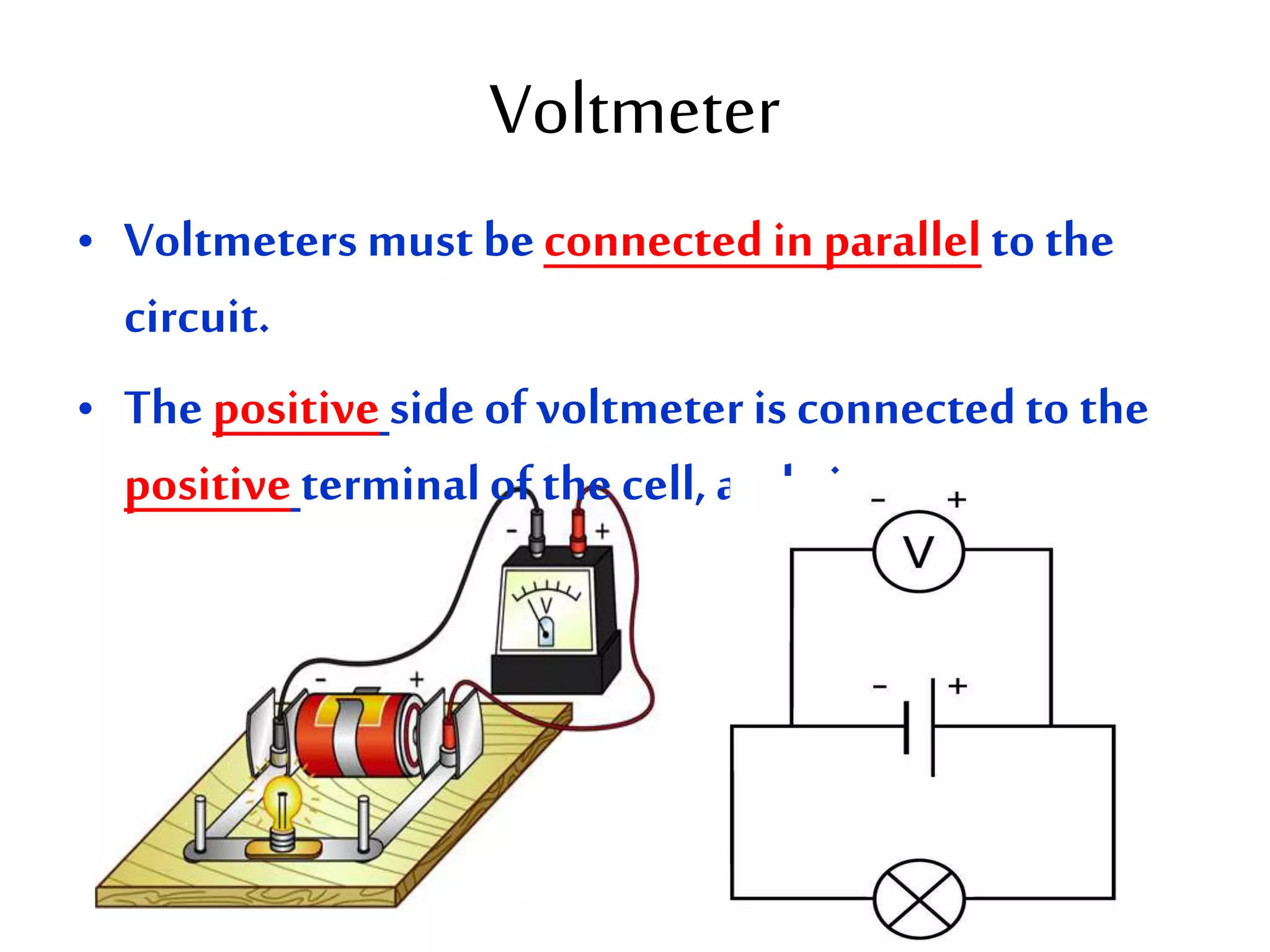
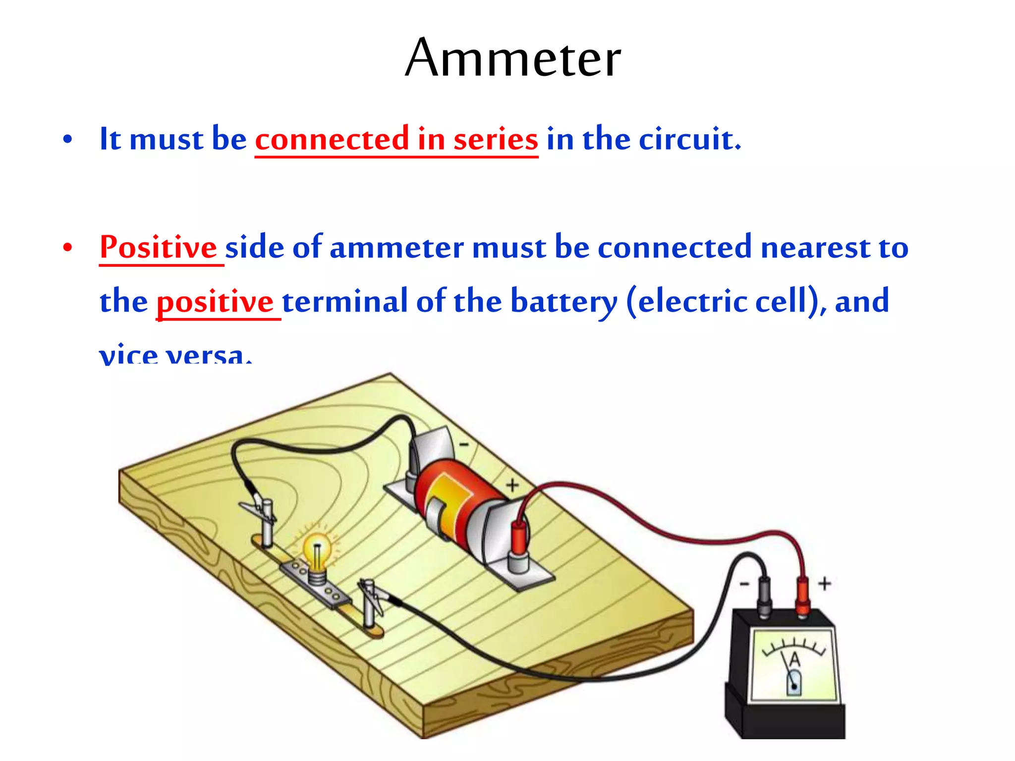
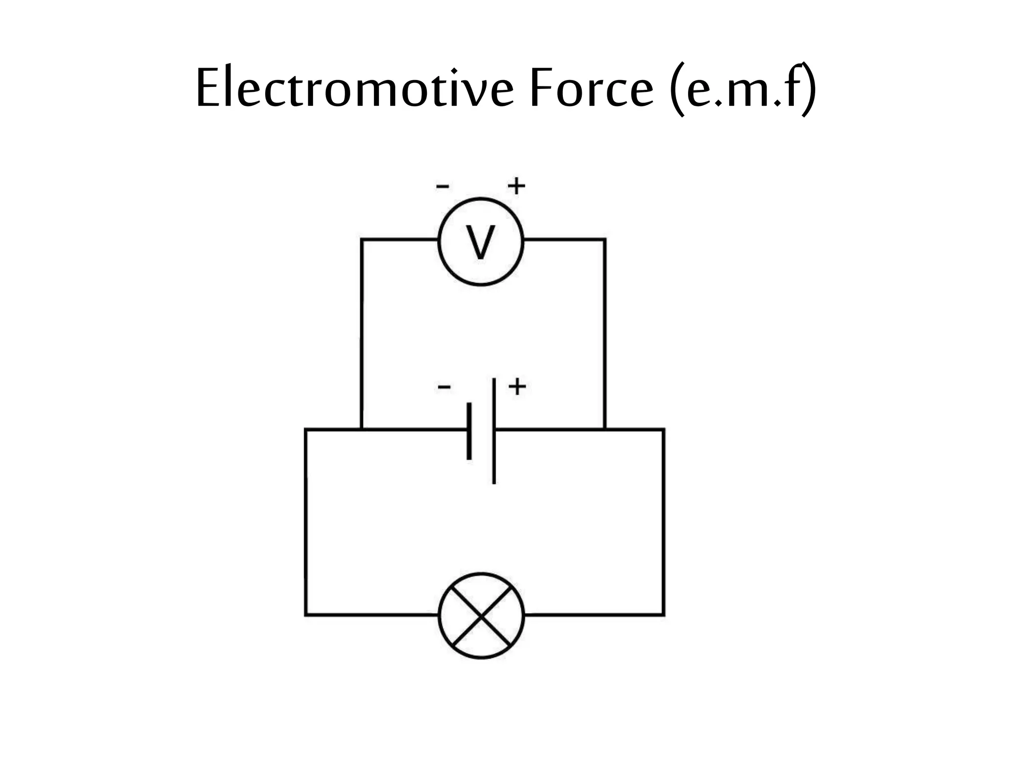
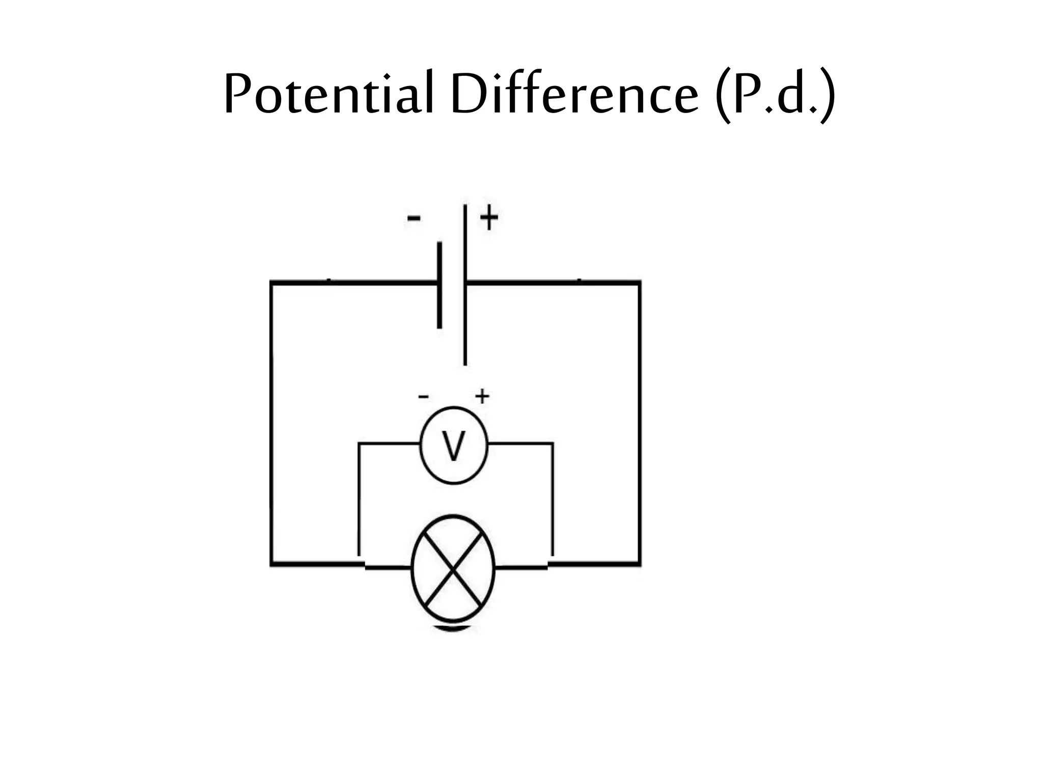
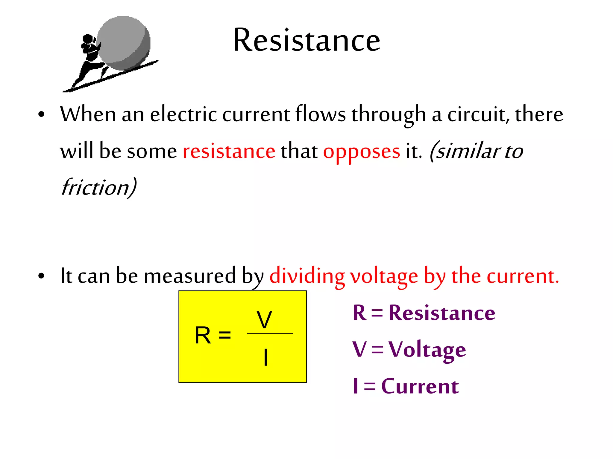
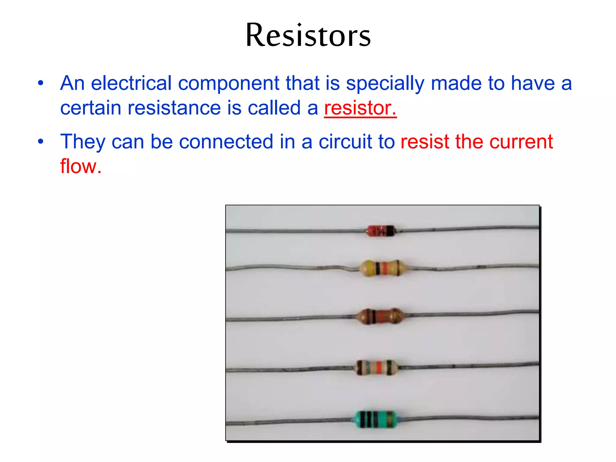
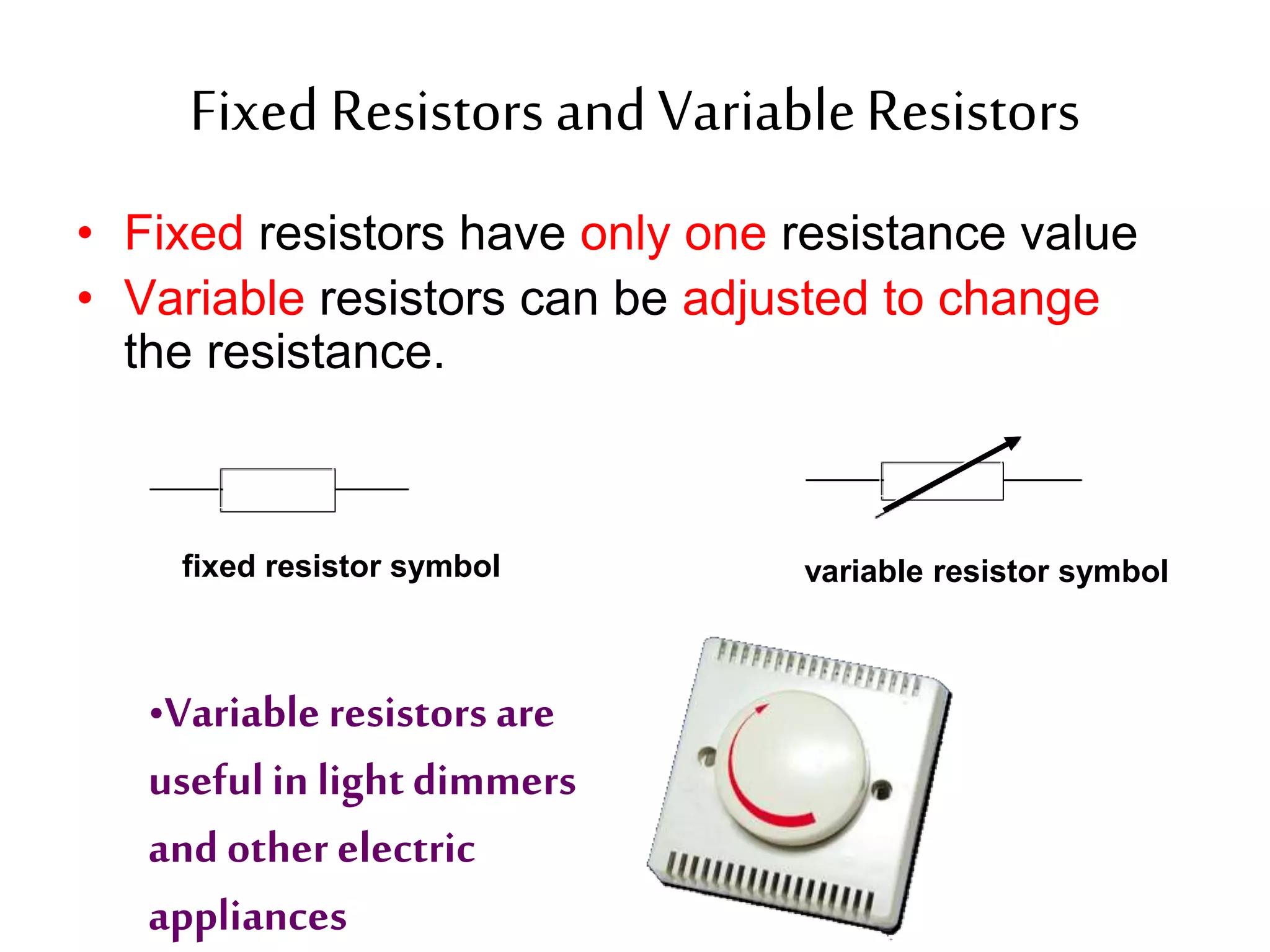
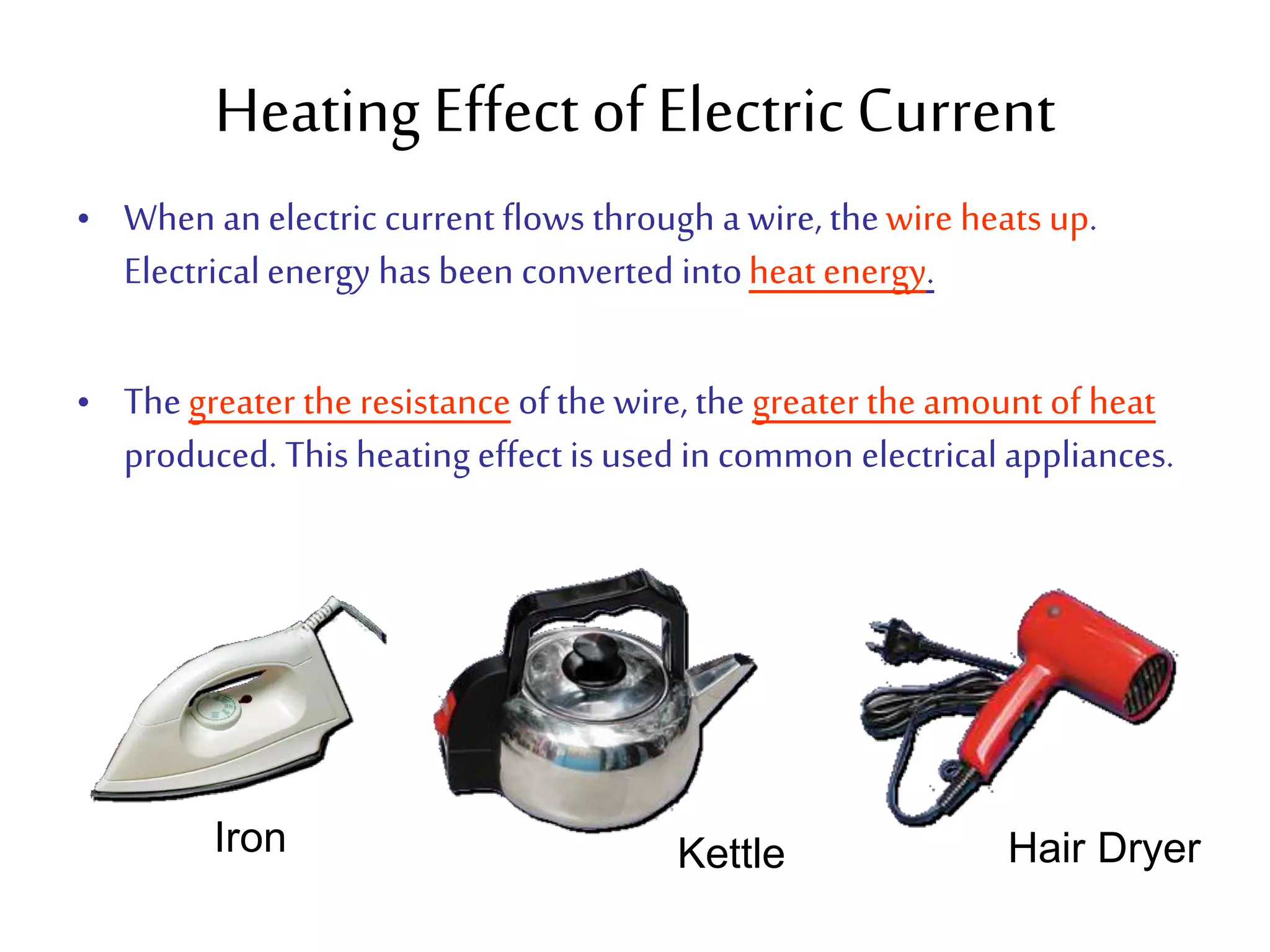
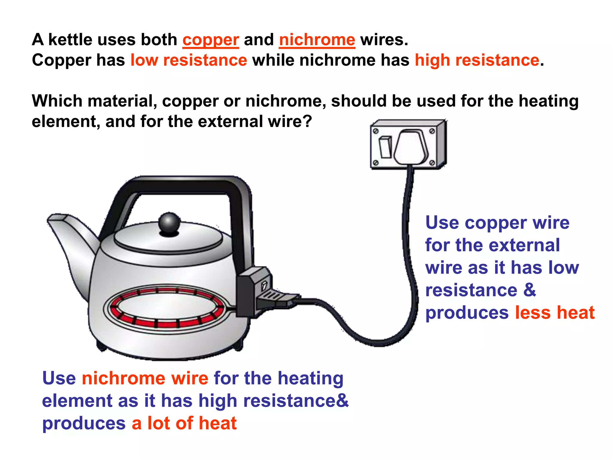
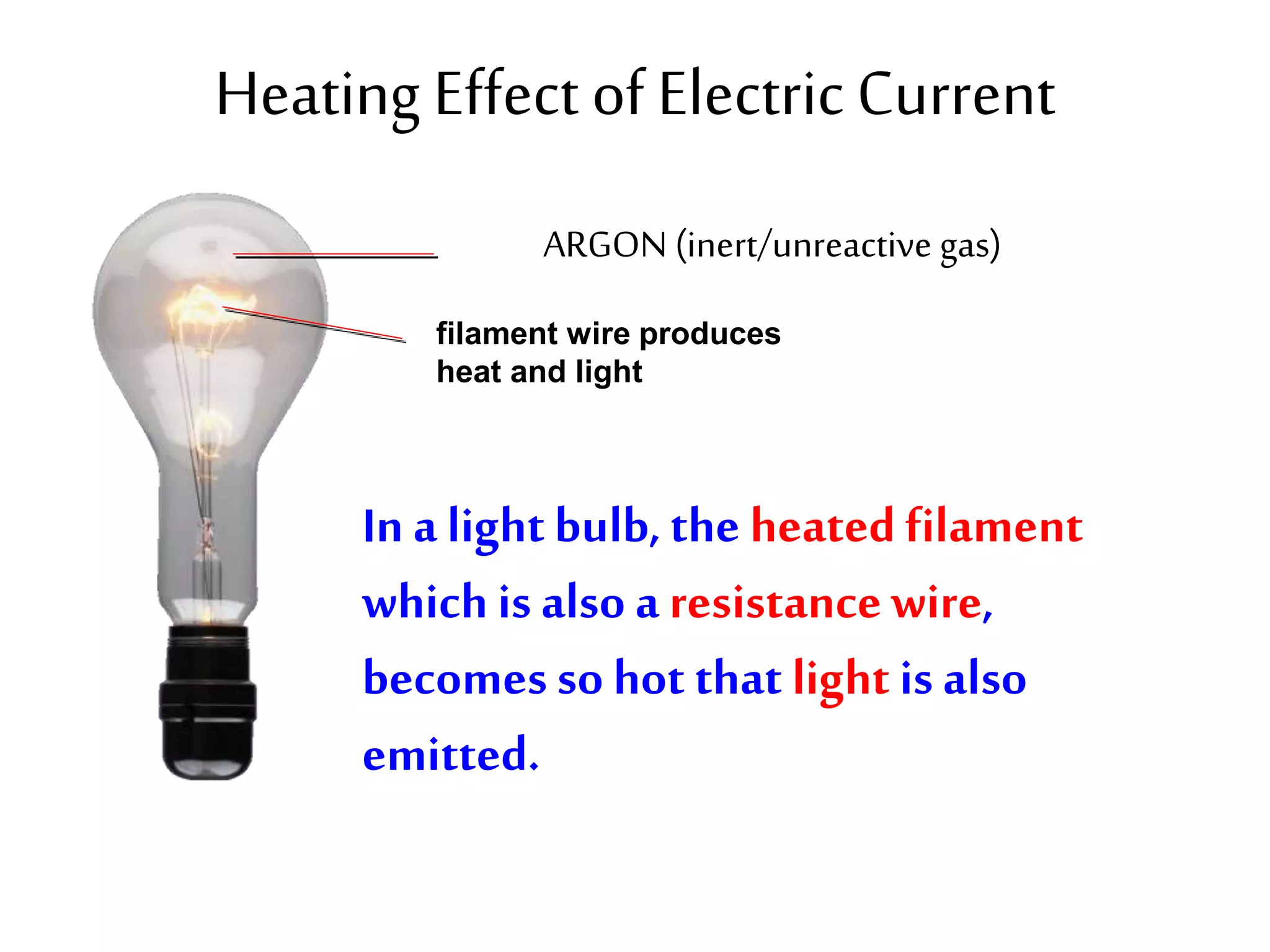
2. It explains how circuits work and the role of components like batteries, wires, switches and resistors. Resistance opposes the flow of current.
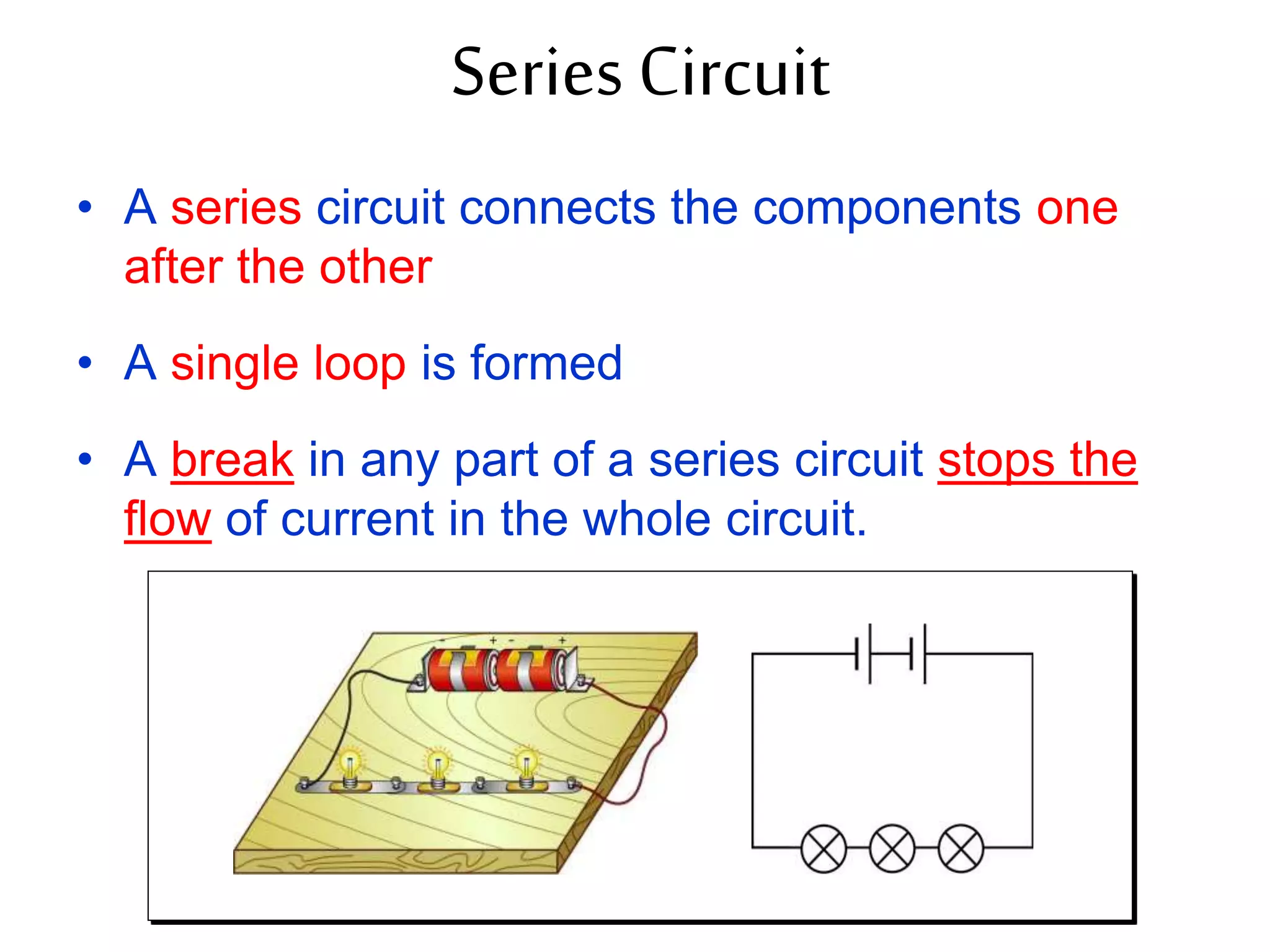
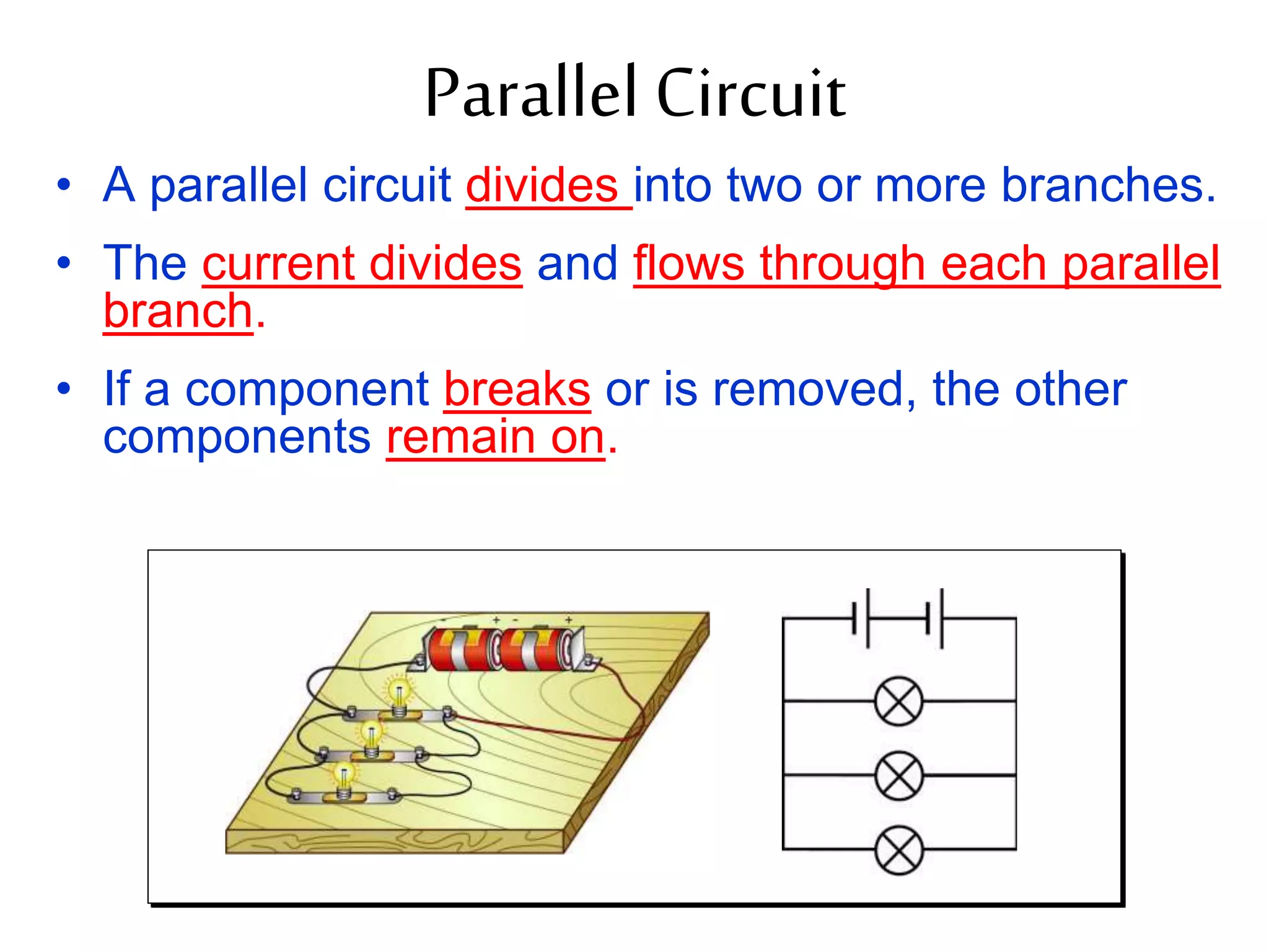
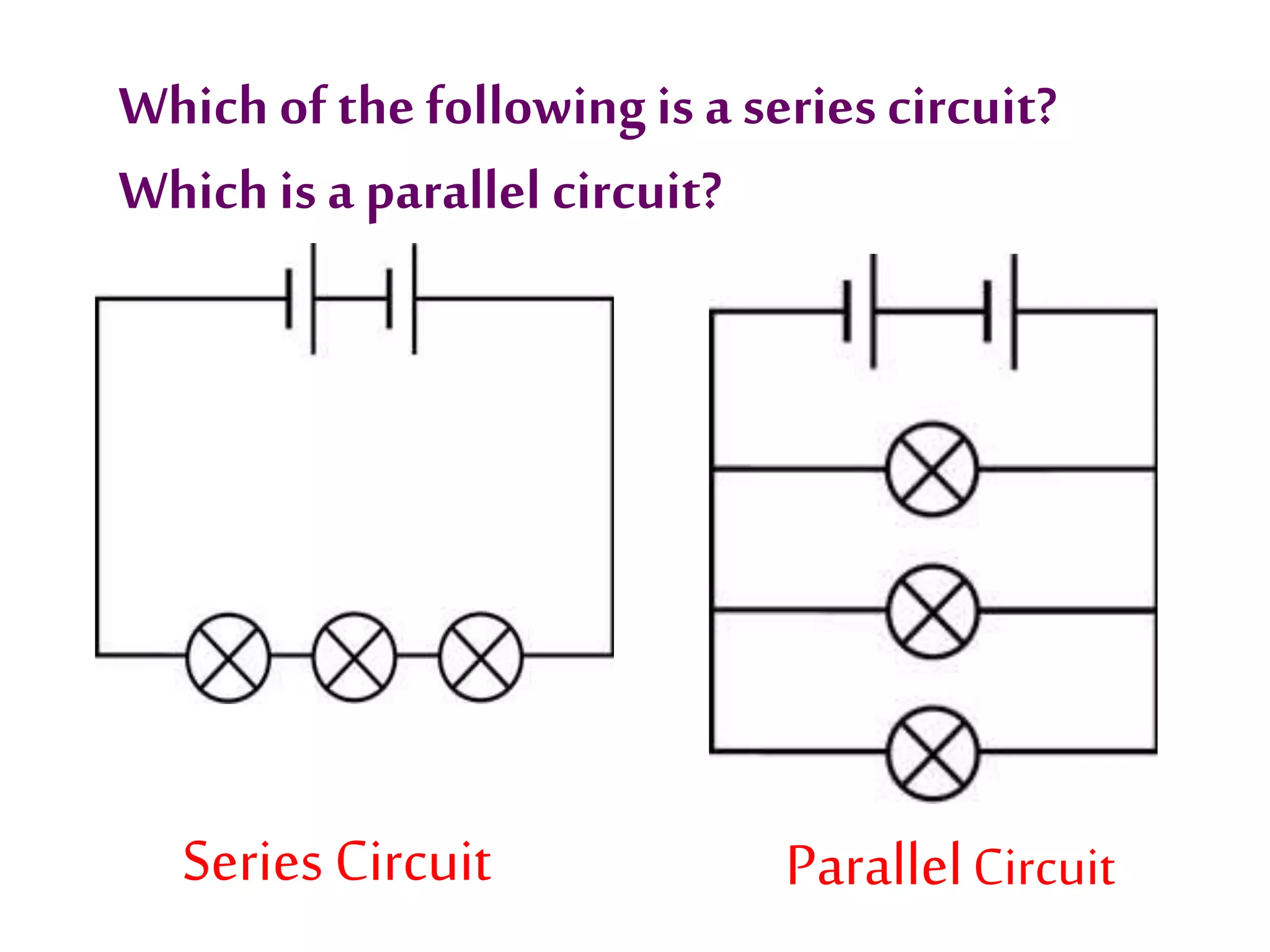
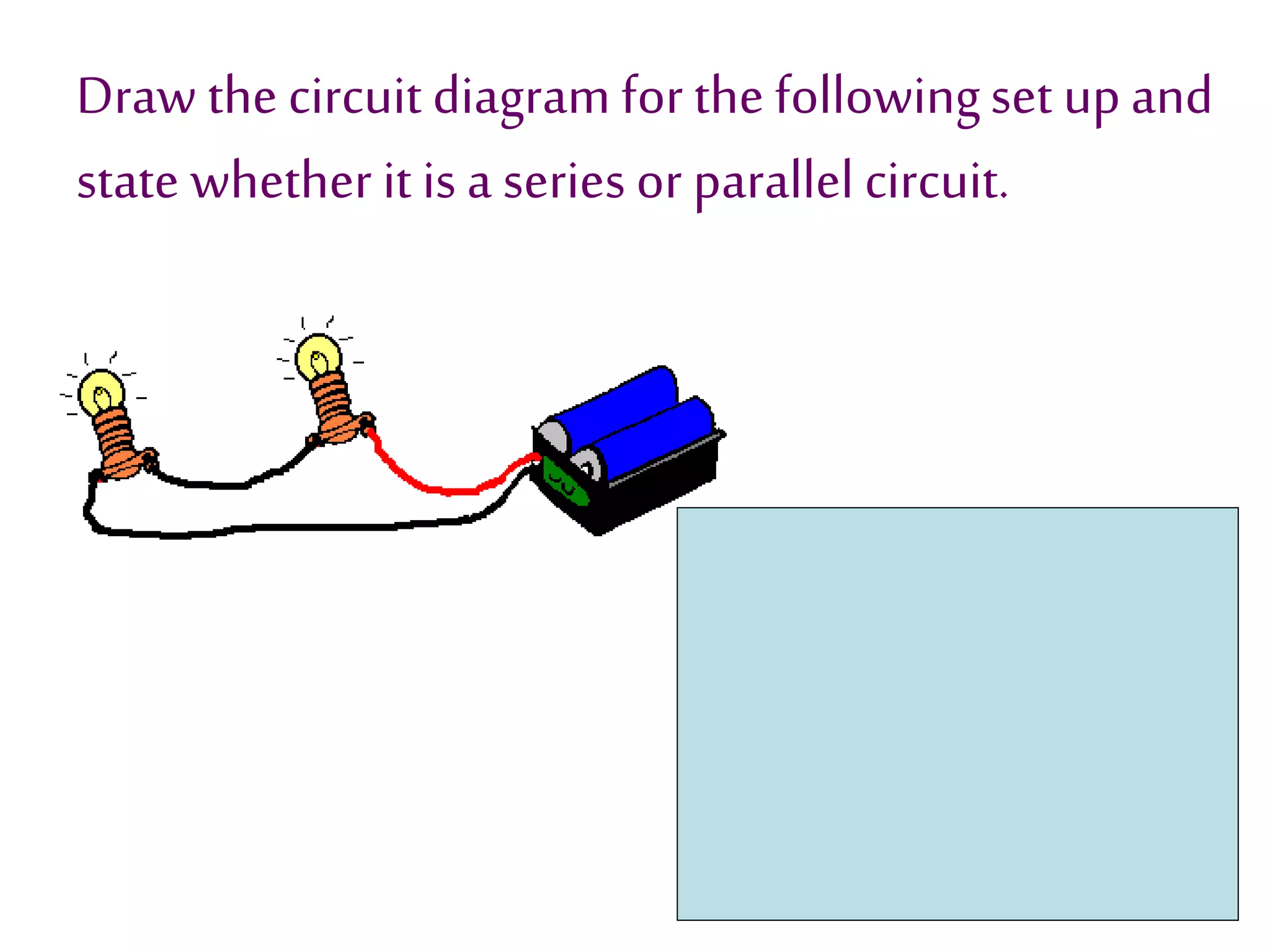
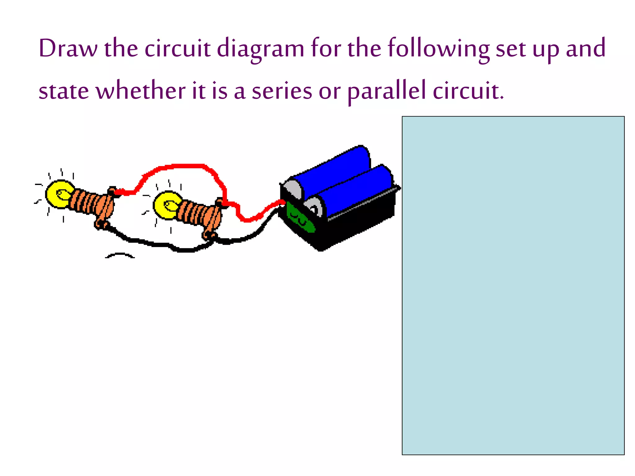
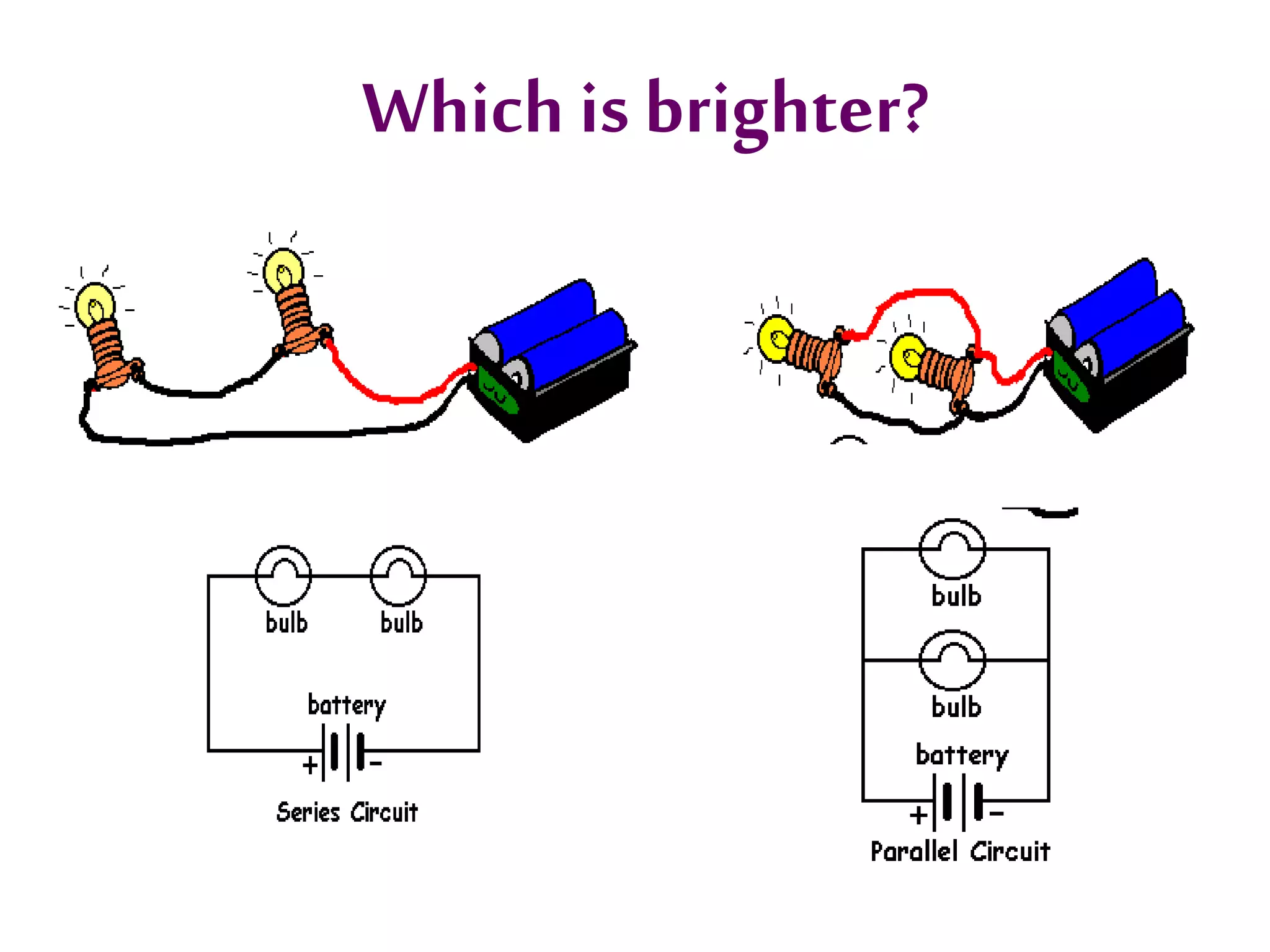
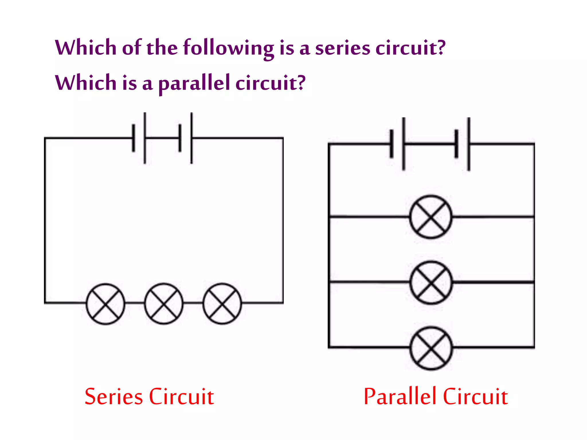
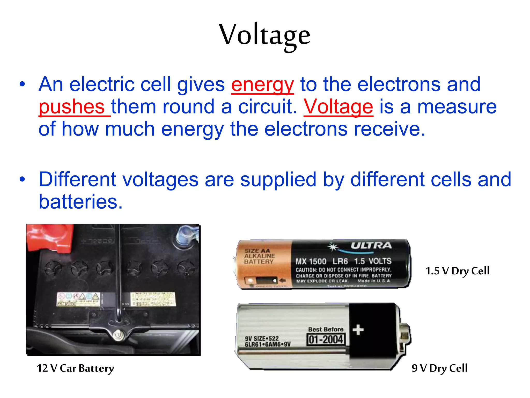
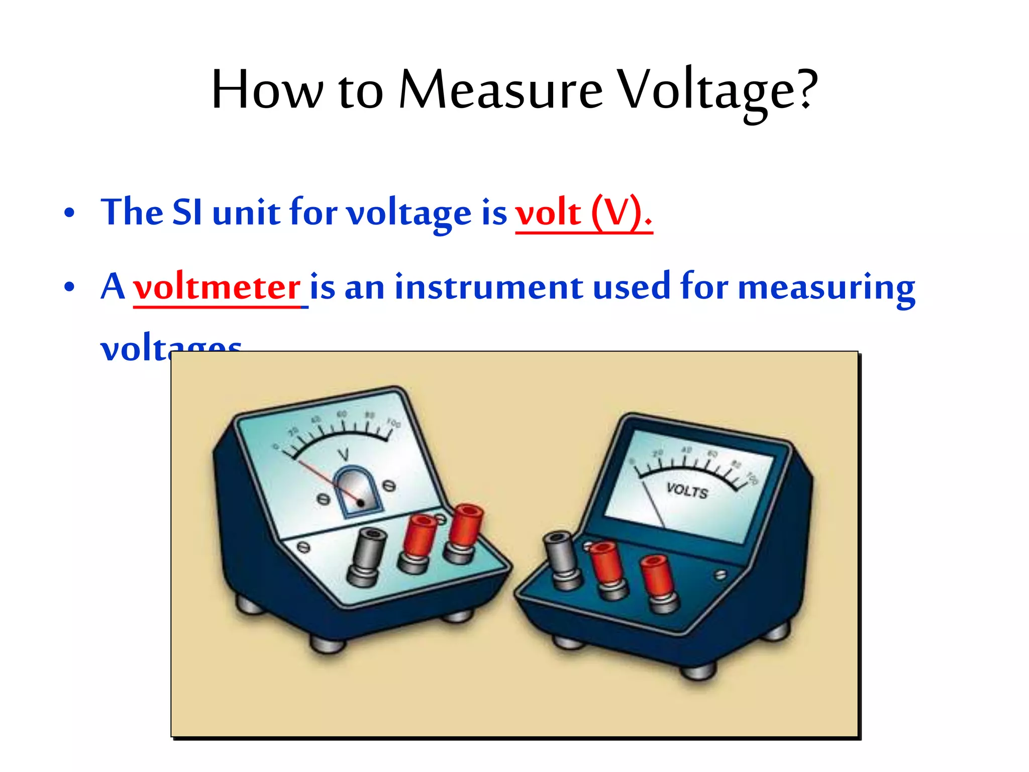
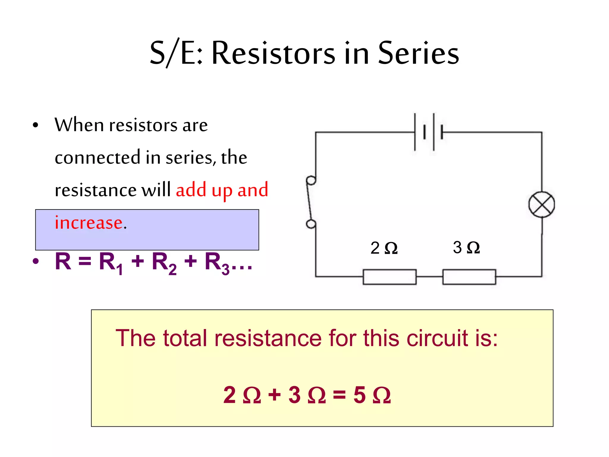
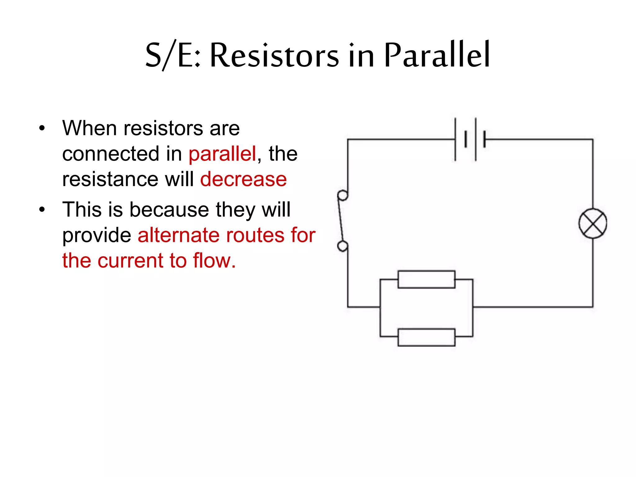
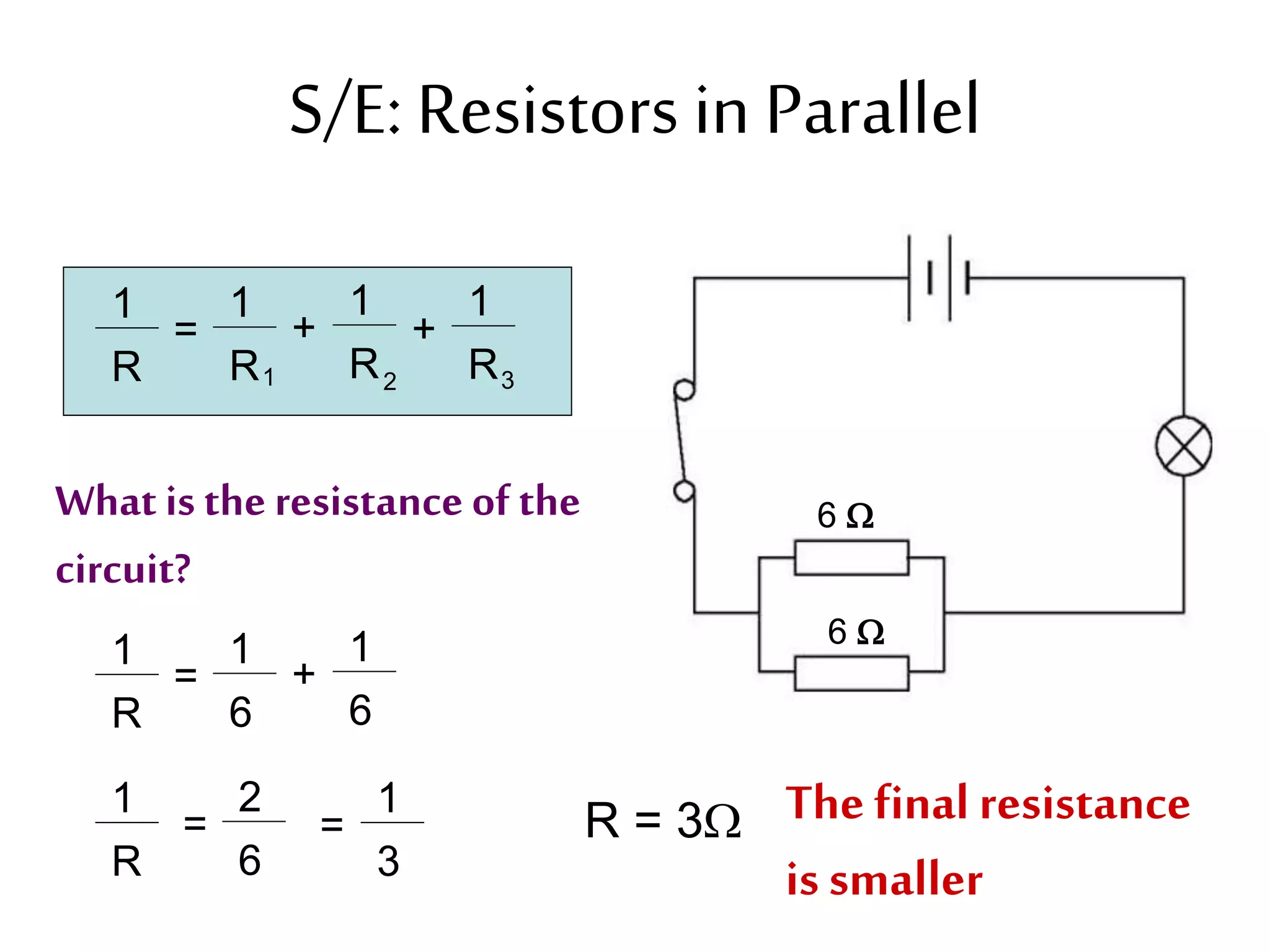
3. It introduces common circuit types like series and parallel and how resistance is calculated and changes between the two circuit arrangements. Measurement units like volts and ohms are also defined.