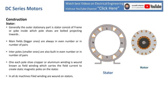
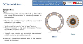
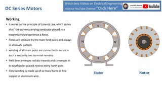
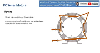
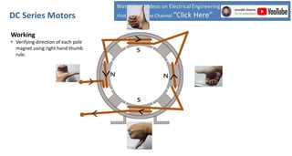
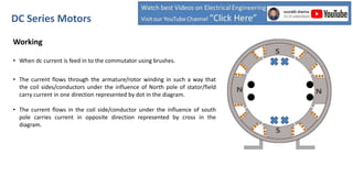
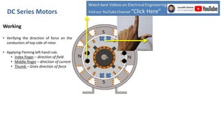
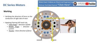
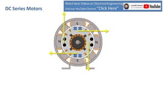
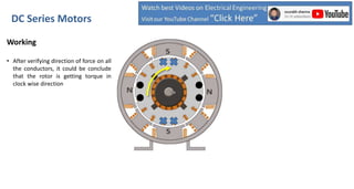
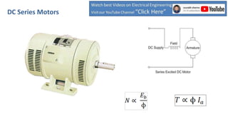
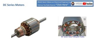
DC Series Motors
• Dc series motors are highly utilized in so
many industrial application due to its high
starting torque characteristic
Construction
Stator:
• Generally the outer stationary part is stator consist of Frame
or yoke inside which pole shoes are bolted projecting
Inwards .
• Main fields (bigger ones) are always in even number or in
number of pairs
• Inter poles (smaller ones) are also built in even number or in
number of pairs
• One each pole shoe cropper or aluminum winding is wound
known as field winding which carries the field current to
create static magnetic poles on the stator.
• In all dc machines Filed winding are wound on stators.
DC Series Motors
Stator
Construction
Rotor:
• Central rotating part is known as rotor built up of laminated
core having multiple number of slots(axially oriented) on
outer periphery.
• The rotor slots consist of armature conductors are connected
to form close type winding.
• Winding could be wound in “lap” or “wave” patterns
• The complete core is on high grade stainless steel shaft also
keyed to it so as to avoid slipping.
• The shaft is also mounted with commutator ring made up of
multiple number of commutator segments.
• From each commutator segments ends of the armature
winding are connected.
DC Series Motors
Stator
Related Videos; Click
Or Skip to Next Slide
Main Field Pole
Inter-pole
Yoke
Pole Shoe
Armature/ Rotor core
Armature winding
Commutator
Shaft
Inter-pole Winding
Field Winding
Stator Rotor
DC Series Motors
Construction
• Rotor is placed inside the stator and separated from it by small
air gap and free to rotate.
• Rotor is supported by the end cover on both side of the motor
frame with the help of bearings.
• Brushes feeds direct electric current in to the armature winding
pressing on commutator segment.
• Number of brushes are always equal to number of main poles
• Four carbon brushes are in this case of four pole shunt motor
• brushes are placed in intern polar region.
DC Series Motors
Working
• It works on the principle of Lorentz Law, which states
that “the current carrying conductor placed in a
magnetic field experience a force.
• Fields are produce by the main field poles and always
in alternate pattern.
• winding of all main poles are connected in series in
such a way only two terminal remains.
• Field lines emerges radialy inwards and converges in
to south poles placed next to every north pole.
• Field winding is made up of so many turns of fine
copper or aluminum wire.
DC Series Motors
Stator
Working
• Simple representation of field winding.
• Current enters in to first pole form one end and exit
form another terminal from last pole.
DC Series Motors
Related Videos; Click
Or Skip to Next Slide
Working
• Verifying direction of each pole
magnet using right hand thumb
rule.
DC Series Motors
Working
• Wiring connection of burses.
• Two brushes are given Positive
voltage and two are given negative.
DC Series Motors
Related Videos; Click
Or Skip to Next Slide
Working
• When dc current is feed in to the commutator using brushes.
• The current flows through the armature/rotor winding in such a way that
the coil sides/conductors under the influence of North pole of stator/field
carry current in one direction represented by dot in the diagram.
• The current flows in the coil side/conductor under the influence of south
pole carries current in opposite direction represented by cross in the
diagram.
DC Series Motors
DC Series Motors
Working
• Verifying the direction of force on the
conductors of Left hand side of rotor.
• Applying Fleming left hand rule.
• Index finger – direction of field
• Middle finger – direction of
current
• Thumb – Gives direction of force
DC Series Motors
Working
• Verifying the direction of force on the
conductors of top side of rotor.
• Applying Fleming left hand rule.
• Index finger – direction of field
• Middle finger – direction of current
• Thumb – Gives direction of force
DC Series Motors
Working
• Verifying the direction of force on the
conductors of right side of rotor.
• Applying Fleming left hand rule.
• Index finger – direction of field
• Middle finger – direction of
current
• Thumb – Gives direction of force
DC Series Motors
Working
• Verifying the direction of force on the
conductors of bottom side of rotor.
• Applying Fleming left hand rule.
• Index finger – direction of field
• Middle finger – direction of
current
• Thumb – Gives direction of force
DC Series Motors
DC Series Motors
Working
• After verifying direction of force on all
the conductors, it could be conclude
that the rotor is getting torque in
clock wise direction
DC Series Motors
Related Videos; Click
Or Skip to Next Slide
DC Series Motors
DC Series Motors
DC Series Motors
Related Videos; Click
Thank You

Dc Series Motor

  • 1.
    DC Series Motors •Dc series motors are highly utilized in so many industrial application due to its high starting torque characteristic
  • 2.
    Construction Stator: • Generally theouter stationary part is stator consist of Frame or yoke inside which pole shoes are bolted projecting Inwards . • Main fields (bigger ones) are always in even number or in number of pairs • Inter poles (smaller ones) are also built in even number or in number of pairs • One each pole shoe cropper or aluminum winding is wound known as field winding which carries the field current to create static magnetic poles on the stator. • In all dc machines Filed winding are wound on stators. DC Series Motors Stator
  • 3.
    Construction Rotor: • Central rotatingpart is known as rotor built up of laminated core having multiple number of slots(axially oriented) on outer periphery. • The rotor slots consist of armature conductors are connected to form close type winding. • Winding could be wound in “lap” or “wave” patterns • The complete core is on high grade stainless steel shaft also keyed to it so as to avoid slipping. • The shaft is also mounted with commutator ring made up of multiple number of commutator segments. • From each commutator segments ends of the armature winding are connected. DC Series Motors Stator
  • 4.
    Related Videos; Click OrSkip to Next Slide
  • 5.
    Main Field Pole Inter-pole Yoke PoleShoe Armature/ Rotor core Armature winding Commutator Shaft Inter-pole Winding Field Winding Stator Rotor DC Series Motors
  • 6.
    Construction • Rotor isplaced inside the stator and separated from it by small air gap and free to rotate. • Rotor is supported by the end cover on both side of the motor frame with the help of bearings. • Brushes feeds direct electric current in to the armature winding pressing on commutator segment. • Number of brushes are always equal to number of main poles • Four carbon brushes are in this case of four pole shunt motor • brushes are placed in intern polar region. DC Series Motors
  • 7.
    Working • It workson the principle of Lorentz Law, which states that “the current carrying conductor placed in a magnetic field experience a force. • Fields are produce by the main field poles and always in alternate pattern. • winding of all main poles are connected in series in such a way only two terminal remains. • Field lines emerges radialy inwards and converges in to south poles placed next to every north pole. • Field winding is made up of so many turns of fine copper or aluminum wire. DC Series Motors Stator
  • 8.
    Working • Simple representationof field winding. • Current enters in to first pole form one end and exit form another terminal from last pole. DC Series Motors
  • 9.
    Related Videos; Click OrSkip to Next Slide
  • 10.
    Working • Verifying directionof each pole magnet using right hand thumb rule. DC Series Motors
  • 11.
    Working • Wiring connectionof burses. • Two brushes are given Positive voltage and two are given negative. DC Series Motors
  • 12.
    Related Videos; Click OrSkip to Next Slide
  • 13.
    Working • When dccurrent is feed in to the commutator using brushes. • The current flows through the armature/rotor winding in such a way that the coil sides/conductors under the influence of North pole of stator/field carry current in one direction represented by dot in the diagram. • The current flows in the coil side/conductor under the influence of south pole carries current in opposite direction represented by cross in the diagram. DC Series Motors
  • 14.
  • 15.
    Working • Verifying thedirection of force on the conductors of Left hand side of rotor. • Applying Fleming left hand rule. • Index finger – direction of field • Middle finger – direction of current • Thumb – Gives direction of force DC Series Motors
  • 16.
    Working • Verifying thedirection of force on the conductors of top side of rotor. • Applying Fleming left hand rule. • Index finger – direction of field • Middle finger – direction of current • Thumb – Gives direction of force DC Series Motors
  • 17.
    Working • Verifying thedirection of force on the conductors of right side of rotor. • Applying Fleming left hand rule. • Index finger – direction of field • Middle finger – direction of current • Thumb – Gives direction of force DC Series Motors
  • 18.
    Working • Verifying thedirection of force on the conductors of bottom side of rotor. • Applying Fleming left hand rule. • Index finger – direction of field • Middle finger – direction of current • Thumb – Gives direction of force DC Series Motors
  • 19.
  • 20.
    Working • After verifyingdirection of force on all the conductors, it could be conclude that the rotor is getting torque in clock wise direction DC Series Motors
  • 21.
    Related Videos; Click OrSkip to Next Slide
  • 22.
  • 23.
  • 24.
  • 25.