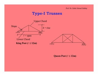
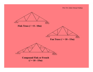
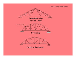
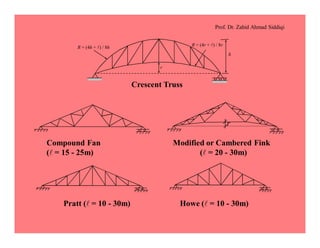
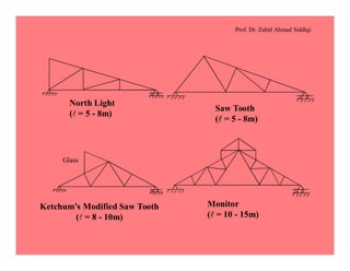
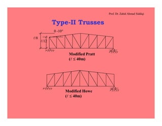
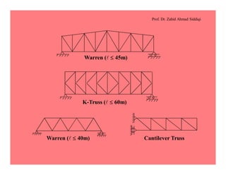
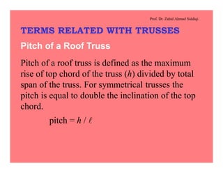
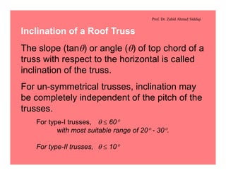
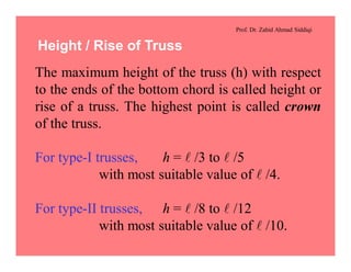
This document discusses the properties and analysis of trusses. It defines a truss as a frame structure where all members experience axial forces. Trusses are analyzed as pin-jointed frames if the joints intersect at a single point and loads are only applied at panel points. The document compares trusses to rigid frames and outlines various truss types including common roof trusses like the Howe, Pratt, Fink and Warren trusses. It also defines related terms like pitch, rise, purlins and loads on truss roofs.
A plate girder is a beam composed of welded or riveted steel plates. It consists of two flanges and a web plate. The flanges resist bending moments while the web resists shear forces. Plate girders are commonly used for longer spans than ordinary beams, with spans ranging from 14-40 meters for railroads and 24-46 meters for highways. They have a high depth to thickness ratio for the web, making it slender. Stiffeners are added to the web to prevent buckling. Plate girders are an economical choice for longer spans where their design can be optimized for requirements.
Wind load calculations were performed for a 10-story building with a height of 30 meters located in Vadodara, India. The design wind speed was calculated at different heights using the basic wind speed, probability, terrain, and topography factors according to Indian code IS 875. The design wind pressure was then determined and used to calculate the wind load in kN/m applying the effective frontal area and force coefficient. Finally, the wind load was calculated at each floor level.
The document summarizes the design of a steel exhibition building with a circular plan. It describes the architectural features of the building including the dimensions of the exhibition hall and stalls. It then discusses the structural analysis conducted using STAAD Pro software and consideration of various loads. Next, it details the design of key structural elements like curved beams, trusses, bracings, columns, and base plates. Design calculations are provided for the curved beams. Finally, it provides a bill of materials and concluding remarks on the benefits of the tubular structural design.
This document discusses riveted connections in steel structures. It describes the different types of rivets, including their shape and method of installation. Some key types are snap headed rivets, pan headed rivets, and flat counter sunk rivets. It also outlines the advantages and disadvantages of riveted connections. Advantages include ease of installation without electricity, while disadvantages include noise and required skilled labor. The document further explains different riveted joint configurations, including lap joints and butt joints, providing examples of single and double riveted versions of each. Finally, it briefly outlines potential failure modes of riveted connections, such as shear failure of rivets or plates, and bearing failure of plates or
This document provides an overview of the design of steel beams. It discusses various beam types and sections, loads on beams, design considerations for restrained and unrestrained beams. For restrained beams, it covers lateral restraint requirements, section classification, shear capacity, moment capacity under low and high shear, web bearing, buckling, and deflection checks. For unrestrained beams, it discusses lateral torsional buckling, moment and buckling resistance checks. Design procedures and equations for determining effective properties and capacities are also presented.
The document provides details on the design of a reinforced concrete column footing to support a column load of 1100kN from a 400mm square column. It describes the design process which includes determining the footing size, calculating bending moment, reinforcement requirements, checking shear capacity and development length. The design example shows a 3.5m x 3.5m square footing with 12mm diameter bars at 100mm c/c is adequate to support the given load based on the specified material properties and design codes. Reinforcement and footing details are also provided.
The document discusses the design of staircases. It begins by defining key components of staircases like treads, risers, stringers, etc. It then describes different types of staircases such as straight, doglegged, and spiral. The document outlines considerations for designing staircases like dimensions, loads, and structural behavior. It provides steps for geometric design, load calculations, structural analysis, reinforcement design, and detailing of staircases. Numerical examples are also included to illustrate the design process.
Calulation of deflection and crack width according to is 456 2000Vikas Mehta
This document discusses the calculation of crack width in reinforced concrete flexural members. It provides information on:
1) Crack width is calculated to satisfy serviceability limits and is only relevant for Type 3 pre-stressed concrete members that crack under service loads.
2) Crack width depends on factors like amount of pre-stress, tensile stress in bars, concrete cover thickness, bar diameter and spacing, member depth and location of neutral axis, bond strength, and concrete tensile strength.
3) The method of calculation involves determining the shortest distance from the surface to a bar and using equations involving member depth, neutral axis depth, average strain at the surface level. Permissible crack widths are specified depending on exposure
This presentation summarizes the key aspects of one-way slab design. It defines one-way slabs as having an aspect ratio of 2:1 or greater, with bending primarily along the long axis. The presentation discusses the types of one-way slabs including solid, hollow, and ribbed. It also outlines the design considerations for one-way slabs according to the ACI code, including minimum thickness, reinforcement ratios, and bar spacing. An example problem demonstrates how to design a one-way slab for a given set of loading and dimensional conditions.
The document discusses various types of structural connections. It begins by defining connections as devices that join structural elements together to safely transfer forces. Connection design is more critical than member design. Failures usually occur at connections and can cause collapse.
The document then discusses different types of connections, including welded, riveted, and bolted connections. Connections are further classified based on the forces transferred, such as truss connections, fully restrained/moment connections, and partially restrained/shear connections. Specific connection types for buildings and frames like moment and shear connections are also explained. Design considerations for various structural connections like weld values, bolt values, and anchor bolts are provided.
This document lists various types of loads that structures must be designed to support, including dead loads, live loads, wind loads, snow loads, and earthquake loads. It also provides density and load-bearing information for common building materials and minimum recommended live loads for different building types. Live load reductions of 10-50% are suggested for floors above the one being designed. Finally, a formula is given for calculating wind load pressure based on wind speed.
Shoring is the construction of a temporary structure to support an unsafe or unstable structure. There are three main types of shoring: raking shores, flying shores, and dead shores. Raking shores use inclined members called rakers to provide lateral support to walls. Flying shores provide temporary support between party walls when an intermediate building is demolished. Dead shores provide vertical support to walls and structures when the lower part of a wall is removed, such as to add an opening.
This document discusses roof trusses, including their components, designs, fabrication, installation, and safety. It covers truss types, principles of design, how they are assembled using metal connectors, how they provide structure and span for roofs, and how to properly install and brace trusses. Safety measures are emphasized, such as using fall protection when working on trusses.
Footings transfer structural loads from a building to the ground. This document discusses various types of footings and their design procedures. Spread footings are the most common type and are proportioned to have an area large enough that soil and building settlement will be minimized. The general design process involves checking that factored loads are less than the soil's allowable bearing capacity and footing thickness is sufficient to resist punching and beam shear. Reinforcement is calculated and placed to resist bending stresses. Combined and strap footings are also discussed along with their unique design considerations. Brick footings can be used for small residential loads.
This document discusses the analysis and design of reinforced concrete footings. It describes different types of footings including isolated, combined, continuous, and raft foundations. It also covers design considerations such as minimum thickness, concrete cover, reinforcement sizes and spacing, and critical sections. An example is provided to demonstrate the step-by-step design of an isolated square footing, calculating loads, sizing the footing, checking effective depth, determining steel requirements, and verifying hook and dowel bar needs.
information on types of beams, different methods to calculate beam stress, design for shear, analysis for SRB flexure, design for flexure, Design procedure for doubly reinforced beam,
This document discusses the design of beams. It defines different types of beams like floor beams, girders, lintels, purlins, and rafters. It describes how beams are classified based on their support conditions as simply supported, cantilever, fixed, or continuous beams. Commonly used beam sections include universal beams, compound beams, and composite beams. The document also covers plastic analysis of beams, classification of beam sections, and failure modes of beams.
This document discusses reinforced concrete columns. It begins by defining columns and different column types, including based on shape, reinforcement, loading conditions, and slenderness ratio. Short columns fail due to material strength while slender columns are at risk of buckling. The document covers column design considerations like unsupported length and effective length. It provides examples of single storey building column design and discusses minimum longitudinal reinforcement requirements in columns.
The document discusses ductility and ductile detailing in reinforced concrete structures. It states that structures should be designed to have lateral strength, deformability, and ductility to resist earthquakes with limited damage and no collapse. Ductility allows structures to develop their full strength through internal force redistribution. Detailing of reinforcement is important to avoid brittle failure and induce ductile behavior by allowing steel to yield in a controlled manner. Shear walls are also discussed as vertical reinforced concrete elements that help structures resist earthquake loads in a ductile manner.
This document discusses counterfort retaining walls. It defines a retaining wall and lists common types, focusing on counterfort retaining walls. It describes the components and mechanics of counterfort walls, noting they are more economical than cantilever walls for heights over 6 meters. The document also covers forces acting on retaining walls, methods for calculating active and passive earth pressures, and stability conditions walls must satisfy including factors of safety against overturning and sliding and limiting maximum pressure at the base.
This document provides guidance on the design of lacing and battens for built-up compression members. It discusses the key design considerations and calculations for both single and double lacing systems, including the angle of inclination, slenderness ratio, effective lacing length, bar width and thickness. Similar guidelines are given for battens, covering spacing, thickness, effective depth, transverse shear and overlap. The document also includes an example problem on designing a slab foundation for a column with given load and material properties.
This document provides an overview of different types of retaining walls, including gravity, cantilever, counterfort, sheet pile, and diaphragm walls. It discusses the key components and design considerations for gravity and cantilever retaining walls. Gravity walls rely on their own weight for stability, while cantilever walls consist of a vertical stem with a heel and toe slab acting as a cantilever beam. The document also covers lateral earth pressures, drainage of retaining walls, uses of sheet pile walls, and construction methods for diaphragm walls.
The document discusses different methods of designing concrete structures, focusing on the limit state method. It describes the limit state method's goal of achieving an acceptable probability that a structure will not become unsuitable for its intended use during its lifetime. The document then discusses stress-strain curves for concrete and steel. It covers stress block parameters and equations for calculating the depth of the neutral axis and moment of resistance for singly reinforced concrete beams. The document concludes by providing examples of analyzing an existing beam section and designing a new beam section.
This document discusses the working stress design method for analyzing and designing reinforced concrete beams. It provides equations for determining internal forces, tensile steel ratio, neutral axis depth, and flexural stresses. It also covers topics such as balanced steel ratio, under/over reinforced sections, minimum concrete cover/bar spacing, and designing rectangular and cantilever beams. Doubly reinforced beams are discussed for cases where the cross section dimensions are restricted and the external moment exceeds the section's moment capacity.
Doubly reinforced beams have both tension and compression reinforcement, allowing for a shallower beam depth than a singly reinforced beam. There are two cases for the behavior of doubly reinforced beams at ultimate loading:
1) Case I occurs when both tension and compression steel yield. The neutral axis depth can be calculated and the moment capacities from compression steel, concrete, and tension steel determined.
2) Case II occurs when only the tension steel yields, and the compression steel does not yield. The strain in the compression steel must be calculated.
The document discusses the behavior of doubly reinforced beams under ultimate loading conditions for both cases when compression steel does and does not yield. It provides equations to calculate forces, strains, and moment
This document discusses design wind load and terminology according to Indian standard code IS 875 (III). It defines key terms like angle of attack, breadth, depth, developed height, effective frontal area, element surface area, force coefficient, gust, peak gust, fetch length, gradient height, pressure coefficient, suction, velocity profile, and topography. It also covers how to calculate design wind speed based on risk coefficient and terrain/height/structure size factor, and how to determine design wind pressure and force coefficients to calculate total wind load on a structure.
Retaining walls are structures used to retain soil or rock in a vertical position. Common materials used include wood, steel, concrete, and gabions. Retaining walls are classified as externally or internally stabilized. Externally stabilized include in-situ and gravity walls. Internally stabilized include reinforced soils and in-site reinforcement. Design considerations include ensuring stability against overturning, sliding, and overloading soils. Design also accounts for active and passive earth pressures. Common gravity wall types are massive gravity, crib, and cantilever walls. In-situ walls include sheet pile, soldier pile, and slurry walls. Reinforced and geosynthetic retaining walls are advanced wall types.
Connections are critical structural elements that join members together to transfer forces safely. Connection design is more important than member design, as connection failures can cause widespread structural collapse. Rigid connections provide strength and ductility to redistribute stresses during events like earthquakes. Common connection types include welded, riveted, and bolted connections, as well as moment connections, shear connections, and splices. Moment connections are particularly important for continuity and resisting lateral loads. Proper connection design is necessary to ensure structural integrity and safety.
1. The document discusses the design of one-way reinforced concrete slabs according to Indian code IS 456:2000.
2. It defines one-way slabs as edge supported slabs spanning in one direction with a ratio of long to short span greater than or equal to 2.
3. The main considerations for slab design discussed are effective span, deflection control, reinforcement requirements including minimum area, maximum bar diameter and cover, and load calculations.
A truss is an assembly of members such as beams, connected by nodes, that creates a rigid structure. In engineering, a truss is a structure that "consists of two-force members only, where the members are organized so that the assemblage as a whole behaves as a single object"
Presentationt design and analysis of multistorey buildingMOHAMMAD HUSAIN
This document provides an acknowledgement and introduction for a project on the structural design of a multi-story residential building in Noida, India. It thanks the mentor, department head, and project members for their support. It includes an AutoCAD model of the building plan and 3D model. It describes some of the building features, such as 12 stories with a height of 3.5 meters per story. It outlines the subsequent sections that will cover the detailed structural design of elements like the water tank, raft foundation, beams, and columns.
Prsesntation on Commercial building ProjectMD AFROZ ALAM
The document describes the trainee's weekly activities during an industrial training at a construction company. Over 8 weeks, the trainee learned about:
1. Layout plans, column reinforcement, beams, and slab details.
2. Reinforcement techniques like lap joints, development lengths, and tie placement.
3. Radiant cooling pipes installed under slabs to provide cooling without AC units.
4. Construction of shear walls, columns, beams and slabs.
5. Block laying for boundary walls using aerated concrete blocks joined with special mortar.
The document discusses the functions and types of casing strings used in oil and gas wells. It describes the different casing strings like conductor casing, surface casing, intermediate casing, and production casing. It also covers casing design criteria like classifications based on outside diameter, length, connections, weight, and grade. The mechanical properties of casing are discussed in relation to withstanding tensile, burst, and collapse loads during drilling and production operations.
The document discusses properties and testing of concrete. It provides information on the constituents of concrete including cement, coarse aggregate, fine aggregate, and water. It also discusses properties of concrete and reinforcements, including their relatively high compressive strength and lower tensile strength. Various tests performed on concrete are mentioned, including tests on workability, compressive strength, flexural strength, and fresh/hardened concrete. Design philosophies for reinforced concrete include the working stress method, ultimate strength method, and limit state method.
Design of Beam- RCC Singly Reinforced BeamSHAZEBALIKHAN1
Concrete beams are an essential part of civil structures. Learn the design basis, calculations for sizing, tension reinforcement, and shear reinforcement for a concrete beam.
This document discusses different types of rigid frame knee connections used to join beams and columns. Square knee joints are described, with and without diagonal stiffeners. Other knee types include square knees with brackets, straight haunched knees, and curved haunched knees. Straight haunched knees provide reasonable stiffness and rotation capacity at a lower cost than other options. The document provides design procedures and an example problem for sizing the components of a square knee connection between a W690×140 beam and W360×110 column.
1. The document discusses different types of joints used to connect structural components including knuckle joints, welded joints, and fillet joints.
2. Knuckle joints provide flexibility and angular movement, while welded joints create a permanent connection through fusion. Fillet joints are made by overlapping plates and welding their edges.
3. The document provides equations to calculate the strength of various welded and fillet joint configurations based on the load applied and permissible stress levels. Examples are given of calculating weld sizes for different joint geometries under static and fatigue loading conditions.
This document provides information on the design of truss roofs, including the properties and types of trusses. It discusses the key differences between rigid frames and trusses, and describes various common truss types (e.g. Queen Post, King Post, Pratt, Howe) for Type I and Type II roofs. It also defines important truss design terms like pitch, inclination, height, and panel length. Finally, it covers components like purlins, sag rods, sheathing, and their functions in truss roof design.
The document discusses different types of beams used in structures. It defines a beam as a structural member subjected primarily to bending. Different types of beams discussed include girders, secondary beams, joists, purlins, stringers, floor beams, girts, lintels and spandrels. Beams are classified based on their position, end conditions, fabrication method, and general span ranges. The document also covers beam analysis, including the flexure formula, stability of beam sections, and classification of beam sections as compact, non-compact and slender.
This document provides information on trusses and roof trusses. It defines trusses as rigid structures made of two-force members arranged in triangular frameworks. Common applications include rooftops and bridges. Pitched roof trusses are most common, with a sloped top chord to facilitate drainage. Analysis involves regarding members as pinned joints transferring only axial forces. Common types include Pratt, Howe, Fink, and Mansard trusses, suited to different spans. Roof trusses provide economic construction and easier assembly than conventional roofs.
This document provides information about the structural analysis and design of an industrial roof truss system. It discusses the design philosophy, methods, types of trusses including roof and bridge trusses. It then describes the specific industrial roof truss system being designed including the selection of truss type, estimation of loads, analysis and design of purlins and sagrods, load analysis, member design, and connection design. Steps in the analysis and design process are outlined and calculations are shown for load calculations, bending moment diagrams, selection of structural sections, and checking stresses.
The document discusses the design procedure for selecting structural steel members according to the Load and Resistance Factor Design (LRFD) method. It provides examples of calculating the load capacity of angle sections, double channel sections, and W-sections. General considerations for selecting sections are also outlined, such as compatibility with connections, minimizing weight, and checking slenderness ratios. Members that experience stress reversal are discussed, outlining three cases to determine whether to consider tensile or compressive forces in design.
Vertical alignment of highway (transportation engineering)Civil Zone
Vertical curves are used in highway design to gradually transition between two different slopes or grades. There are two main types - crest vertical curves, which are used on roadway tops, and sag vertical curves, which are used on dips. The minimum length of a vertical curve is determined based on providing the required stopping sight distance for a given design speed. Additional criteria like passenger comfort, drainage, and appearance may also influence the curve length selected. Longer vertical curves generally provide a smoother ride but require more construction costs.
Traffic studies (transportation engineering)Civil Zone
Traffic studies analyze traffic characteristics to inform transportation design and control. Key studies include traffic volume, speed, origin-destination, and accident analyses. Traffic volume studies count vehicles over time and are used for planning, operations, and structural design. Speed studies measure spot, average, running, and journey speeds to understand traffic patterns and inform control and design. Origin-destination studies identify the origins and destinations of trips to understand land use and travel patterns. Together these studies provide essential traffic data for transportation planning and management.
Level of service (los) multilane hwys 02 (transportation engineering)Civil Zone
This document discusses the analysis of level of service (LOS) on multilane highways. It provides key differences between freeways and multilane highways, such as access control and presence of traffic signals. It then outlines base conditions for LOS analysis on multilane highways, including lane width, lateral clearance, vehicle types, and terrain. The free-flow speed is calculated using factors for these conditions. Examples are provided to demonstrate calculating the free-flow speed using the base free-flow speed and adjustment factors for lane width, lateral clearance, median, and access points. Finally, it shows how to determine the volume-to-capacity ratio and establish the LOS based on density, using values from the example.
Introduction to transportation engineeringCivil Zone
Transportation engineering involves the planning, design, and management of transportation facilities to provide safe and efficient movement of people and goods. A key aspect of transportation engineering is road design. Some essential elements of a typical road cross-section include the traveled way for vehicles, shoulders for stopped vehicles and bicycles, medians to separate opposing traffic, drainage channels to remove surface water, and barriers or guardrails to prevent vehicles from leaving the roadway. Transportation engineers must consider all of these elements and their widths, slopes, and designs to develop roadways that are effective and safe for users.
Highway materials (transportation engineering)Civil Zone
This document discusses various materials used in highway construction. It describes aggregates, which are granular materials used in bases, subbases and backfill. Important properties of aggregates include particle size and hardness. Particle size distribution is determined through grain-size analysis and sieving. Hardness is measured using tests such as the Los Angeles abrasion test. Bituminous materials, commonly known as asphalt, are also discussed. Types of asphalt include asphalt cement and cutback asphalt. Specifications and tests for aggregates and asphalt are provided according to standards like AASHTO and ASTM.
Capacity & level of service (transportation engineering)Civil Zone
This document discusses highway design speed and level of service. It defines design speed as the maximum safe speed for a road based on its geometric design features. Level of service is a qualitative measure of traffic conditions on a roadway, ranging from free-flowing traffic at LOS A to congested traffic at LOS F. The document provides examples of calculating level of service for a highway based on factors like lane width, access points, and traffic volume using methods from the Highway Capacity Manual. It shows how changes to the road design, such as adding lanes or widening lanes, can improve the level of service.
Alighnment & horizontal alignment of highway (transportation engineering)Civil Zone
This document discusses the alignment of highways, including horizontal and vertical elements. It covers topics such as grade line, horizontal and vertical curves, sight distance requirements, and super elevation. The key points are:
- Highway alignment consists of horizontal and vertical elements, including tangents and curves. Curves can be simple, compound, spiral, or reverse.
- Grade line refers to the longitudinal slope/rise of the highway. Factors in selecting a grade line include earthwork, terrain, sight distance, flood levels, and groundwater.
- Horizontal alignment deals with tangents and circular curves that connect changes in direction. Vertical alignment includes highway grades and parabolic curves.
- Proper design of curves
- Hydraulics engineering is the application of fluid mechanics principles to water-related structures like canals, rivers, dams and reservoirs. It is a branch of civil engineering concerned with water flow and conveyance.
- Ancient Egyptians, Mesopotamians, and Armenians made important early contributions to hydraulics engineering, developing irrigation systems using canals and qanats.
- Notable hydraulic structures through history include one of the world's oldest dams built in Egypt between 2950-2690 BC, and ship locks that raised or lowered boats between different water levels.
This document provides an introduction to hydropower engineering. It discusses how hydropower works by capturing the kinetic energy of falling water through turbines connected to generators. The amount of electricity generated depends on water flow rate and head (drop height). It also categorizes different types of hydropower developments including run-of-river, diversion canal, storage, and pumped storage plants. Site selection factors for hydropower include available water resources, water storage capacity, water head, and accessibility of the site.
Dams and Reservoirs -Hydraulics engineeringCivil Zone
Dams are barriers built across rivers or streams to control water flow for uses like irrigation, hydropower, and flood control. The main types are embankment dams made of earth or rock and concrete dams like gravity, arch, and buttress dams. Dams provide benefits like irrigation, power, flood control, and recreation but can also negatively impact river ecosystems and require relocation of people. Engineers consider factors like geology, material availability, and hydrology to select the optimal dam type and site for a given project. Ancillary structures like spillways and outlets control water release.
Similitude and Dimensional Analysis -Hydraulics engineering Civil Zone
This document discusses similitude and dimensional analysis for model testing in hydraulic engineering. It introduces key concepts like similitude, prototype, model, geometric similarity, kinematic similarity, dynamic similarity, dimensionless numbers, and model laws. Reynolds model law is described in detail, which states that the Reynolds number must be equal between the model and prototype for problems dominated by viscous forces, such as pipe flow. An example problem demonstrates how to calculate the velocity and flow rate in a hydraulic model based on given prototype parameters and Reynolds model law.
Beam columns are structural members that experience both bending and axial stresses. They behave similarly to both beams and columns. Many steel building frames have columns that carry significant bending moments in addition to compressive loads. Bending moments in columns are produced by out-of-plumb erection, initial crookedness, eccentric loads, wind loads, and rigid beam-column connections. The interaction of axial loads and bending moments in columns must be considered through an interaction equation to ensure a safe design. Second order effects, or P-Delta effects, produce additional bending moments in columns beyond normal elastic analysis and must be accounted for through moment magnification factors.
This document discusses lap joints, bolted connections, and riveted connections. It provides details on:
- The components and stresses involved in a basic lap joint using a single fastener under tension or compression.
- Requirements for bolted connections including minimum pretension values for high-strength bolts and methods for measuring pretension.
- Types of stresses fasteners experience including shear stresses at the interface of joined parts and bearing stresses transmitted into the surrounding plates.
- Properties and grades of rivets commonly used in structural connections as well as their tensile and shear strengths.
- Methods for calculating the load capacity ("rivet value") of single rivets in lap joints
This document discusses the properties and design of trusses and purlins. It defines key terms related to trusses like panel loads, which are concentrated loads applied at interior panel points calculated based on the roof load and area contributing to that point. Trusses are analyzed considering unit gravity and wind loads, and the principle of superposition is used. The document provides guidelines for designing purlins, including calculating loads, selecting trial sections, checking stresses and dimensions, and designing sag rods if needed. An example is given to demonstrate the purlin design process for given roof load and truss geometry data.
1. The document designs bearing and end bearing stiffeners for a plate girder. For the bearing stiffener, a 200 x 15 mm stiffener plate is required on both sides under the web crippling limit state.
2. For the end bearing stiffener, a 240 x 18 mm stiffener plate is required on both sides due to the web crippling and bearing stiffener requirements at unframed ends.
3. Both designs satisfy all other limit states checked such as web local yielding, web sidesway buckling, and have sufficient weld strength.
The document discusses the benefits of exercise for mental health. Regular physical activity can help reduce anxiety and depression and improve mood and cognitive functioning. Exercise causes chemical changes in the brain that may help protect against mental illness and improve symptoms.
- Plate girders require stiffeners to prevent buckling of the thin webs under compression. Bearing stiffeners are located at supports and concentrated loads, while intermediate stiffeners are spaced along the web.
- Intermediate stiffeners help develop tension field action after the web buckles, allowing the girder to resist higher shear loads through a truss-like action of the stiffened web.
- The design of intermediate stiffeners involves calculating their required spacing and size based on the web dimensions and shear capacity of the girder considering both the initial buckling strength and additional strength from tension field action.
This document discusses design considerations for steel beams, including:
1. Deflection limits for buildings, bridges, and delicate machinery are discussed, ranging from L/360 to L/2000.
2. Initial beam selection can be done by limiting the span-to-depth ratio (L/d) based on the member type to indirectly control deflections.
3. Explicit span-to-depth ratio limits are provided for various member types, such as L/d ≤ 5500/Fy for buildings and L/d ≤ 20 for bridges.
4. Formulas are provided for calculating beam deflections under different loading conditions like uniform and point loads.
This document provides a flow chart for designing built-up compression members and summarizes the design of a sample column consisting of two back-to-back channels with flat lacing. The key steps are: 1) Select a built-up section that satisfies strength and stability requirements, 2) Design flat lacing to resist shear forces using bars of appropriate size, length, and strength, 3) Satisfy design checks for lacing bar geometry and capacity. For the example, two 330x74mm channels are selected and flat lacing with 50x10mm bars 425mm long is designed to resist the shear force.
The document discusses the design of compression members in planar trusses. It provides modifications to the slenderness ratio that must be applied when designing single angle compression members to account for potential torsional buckling. It then outlines a design flow chart for selecting compression member sections, including calculating required member capacity and area, selecting a trial section, and performing various checks related to stability, slenderness ratio and member capacity. An alternate method for selecting W-sections or double angle sections using column selection tables is also described.
Presentation of IEEE Slovenia CIS (Computational Intelligence Society) Chapte...University of Maribor
Slides from talk presenting:
Aleš Zamuda: Presentation of IEEE Slovenia CIS (Computational Intelligence Society) Chapter and Networking.
Presentation at IcETRAN 2024 session:
"Inter-Society Networking Panel GRSS/MTT-S/CIS
Panel Session: Promoting Connection and Cooperation"
IEEE Slovenia GRSS
IEEE Serbia and Montenegro MTT-S
IEEE Slovenia CIS
11TH INTERNATIONAL CONFERENCE ON ELECTRICAL, ELECTRONIC AND COMPUTING ENGINEERING
3-6 June 2024, Niš, Serbia
Low power architecture of logic gates using adiabatic techniquesnooriasukmaningtyas
The growing significance of portable systems to limit power consumption in ultra-large-scale-integration chips of very high density, has recently led to rapid and inventive progresses in low-power design. The most effective technique is adiabatic logic circuit design in energy-efficient hardware. This paper presents two adiabatic approaches for the design of low power circuits, modified positive feedback adiabatic logic (modified PFAL) and the other is direct current diode based positive feedback adiabatic logic (DC-DB PFAL). Logic gates are the preliminary components in any digital circuit design. By improving the performance of basic gates, one can improvise the whole system performance. In this paper proposed circuit design of the low power architecture of OR/NOR, AND/NAND, and XOR/XNOR gates are presented using the said approaches and their results are analyzed for powerdissipation, delay, power-delay-product and rise time and compared with the other adiabatic techniques along with the conventional complementary metal oxide semiconductor (CMOS) designs reported in the literature. It has been found that the designs with DC-DB PFAL technique outperform with the percentage improvement of 65% for NOR gate and 7% for NAND gate and 34% for XNOR gate over the modified PFAL techniques at 10 MHz respectively.
Embedded machine learning-based road conditions and driving behavior monitoringIJECEIAES
Car accident rates have increased in recent years, resulting in losses in human lives, properties, and other financial costs. An embedded machine learning-based system is developed to address this critical issue. The system can monitor road conditions, detect driving patterns, and identify aggressive driving behaviors. The system is based on neural networks trained on a comprehensive dataset of driving events, driving styles, and road conditions. The system effectively detects potential risks and helps mitigate the frequency and impact of accidents. The primary goal is to ensure the safety of drivers and vehicles. Collecting data involved gathering information on three key road events: normal street and normal drive, speed bumps, circular yellow speed bumps, and three aggressive driving actions: sudden start, sudden stop, and sudden entry. The gathered data is processed and analyzed using a machine learning system designed for limited power and memory devices. The developed system resulted in 91.9% accuracy, 93.6% precision, and 92% recall. The achieved inference time on an Arduino Nano 33 BLE Sense with a 32-bit CPU running at 64 MHz is 34 ms and requires 2.6 kB peak RAM and 139.9 kB program flash memory, making it suitable for resource-constrained embedded systems.
We have compiled the most important slides from each speaker's presentation. This year’s compilation, available for free, captures the key insights and contributions shared during the DfMAy 2024 conference.
CHINA’S GEO-ECONOMIC OUTREACH IN CENTRAL ASIAN COUNTRIES AND FUTURE PROSPECTjpsjournal1
The rivalry between prominent international actors for dominance over Central Asia's hydrocarbon
reserves and the ancient silk trade route, along with China's diplomatic endeavours in the area, has been
referred to as the "New Great Game." This research centres on the power struggle, considering
geopolitical, geostrategic, and geoeconomic variables. Topics including trade, political hegemony, oil
politics, and conventional and nontraditional security are all explored and explained by the researcher.
Using Mackinder's Heartland, Spykman Rimland, and Hegemonic Stability theories, examines China's role
in Central Asia. This study adheres to the empirical epistemological method and has taken care of
objectivity. This study analyze primary and secondary research documents critically to elaborate role of
china’s geo economic outreach in central Asian countries and its future prospect. China is thriving in trade,
pipeline politics, and winning states, according to this study, thanks to important instruments like the
Shanghai Cooperation Organisation and the Belt and Road Economic Initiative. According to this study,
China is seeing significant success in commerce, pipeline politics, and gaining influence on other
governments. This success may be attributed to the effective utilisation of key tools such as the Shanghai
Cooperation Organisation and the Belt and Road Economic Initiative.
KuberTENes Birthday Bash Guadalajara - K8sGPT first impressionsVictor Morales
K8sGPT is a tool that analyzes and diagnoses Kubernetes clusters. This presentation was used to share the requirements and dependencies to deploy K8sGPT in a local environment.
Introduction- e - waste – definition - sources of e-waste– hazardous substances in e-waste - effects of e-waste on environment and human health- need for e-waste management– e-waste handling rules - waste minimization techniques for managing e-waste – recycling of e-waste - disposal treatment methods of e- waste – mechanism of extraction of precious metal from leaching solution-global Scenario of E-waste – E-waste in India- case studies.
ACEP Magazine edition 4th launched on 05.06.2024Rahul
This document provides information about the third edition of the magazine "Sthapatya" published by the Association of Civil Engineers (Practicing) Aurangabad. It includes messages from current and past presidents of ACEP, memories and photos from past ACEP events, information on life time achievement awards given by ACEP, and a technical article on concrete maintenance, repairs and strengthening. The document highlights activities of ACEP and provides a technical educational article for members.
1. Prof. Dr. Zahid Ahmad Siddiqi
PROPERTIES OF TRUSSES
Truss is a frame structure in which all the
members have axial forces due to the
following facts:
a. Members are arranged in triangles for
stability.
b. All the joints of a truss are actually
semi-rigid or fully rigid. However,
theoretically, these joints may be
considered as pin joints.
2. Prof. Dr. Zahid Ahmad Siddiqi
The analysis as a pin-jointed frame is
valid provided that the requirements
given in No.3 and 4 are satisfied.
c. Centroidal axes of all the members
meeting at a joint must intersect at a
single point.
d. The loads are only applied at the panel
points.
3. Prof. Dr. Zahid Ahmad Siddiqi
Following is the comparison between rigid
frames and trusses:
a. Joints are considered as having frictionless pins in
trusses with no moment at the member ends. In case
of rigid frames, the members are rigidly connected
having appreciable moments at the member ends.
b. The forces in case of trusses are only axial and
hence the members are equally stressed throughout
their cross-section. In rigid frames, due to bending
moment, the fibers of the cross-section away from
the neutral axis have maximum stresses and the
fibers close to the neutral axis have less stress.
4. Prof. Dr. Zahid Ahmad Siddiqi
c. Because of the above facts, the design of a member
in a case of a truss is economical as compared with
the members of a rigid frame. Hence, trusses become
economical in those cases where the corresponding
construction cost is less as a percentage of the total
cost.
TYPES OF TRUSSES
Trusses can broadly be divided into two
categories, Type -I trusses are preferred in
those areas where snowfall is common and
Type-II trusses used in cot climates.
5. Prof. Dr. Zahid Ahmad Siddiqi
The roofs of Type-I trusses are inclined at
greater angles (10° to 60°) to drain part of the
snow falling on the roof surface.
These may also be preferred if bending
moments are larger near the mid-span and
zero at the ends.
The roofs of Type-II trusses are either nearly
flat or are inclined at angles less than 10°.
6. Prof. Dr. Zahid Ahmad Siddiqi
Type-I Trusses
q
Slope
h = rise
Upper Chord
l = span
Lower Chord
King Post (l £ 12m)
Queen Post (l £ 12m)
7. Prof. Dr. Zahid Ahmad Siddiqi
Fink Truss (l = 8 - 10m)
Fan Truss (l = 10 - 15m)
Compound Fink or French
(l = 10 - 15m)
8. Prof. Dr. Zahid Ahmad Siddiqi
Subdivided Fink
(l = 20 - 30m)
R = (4h + l) / 8h
Bowstring
Parker or Bowstring
9. Prof. Dr. Zahid Ahmad Siddiqi
R = (4h + l) / 8h R = (4r + l) / 8r
h
r
Crescent Truss
r
Compound Fan Modified or Cambered Fink
(l = 15 - 25m) (l = 20 - 30m)
Pratt (l = 10 - 30m) Howe (l = 10 - 30m)
10. Prof. Dr. Zahid Ahmad Siddiqi
If the forces in the diagonal members are all compressive and
that in the vertical members are all tensile, the truss is called
Howe Truss.
In a reverse way if the forces in all the diagonal members are
tensile while the forces in all the vertical members are
compressive, the truss is called Pratt Truss.
The difference between these two trusses is only the
orientation of the diagonals in relation to the applied loads.
In case of Warren Truss, the diagonals alternate in
orientation and also in the sense of forces in them. For all the
roof trusses, the loads are in general applied on the top
chord.
11. Prof. Dr. Zahid Ahmad Siddiqi
Glass
North Light
(l = 5 - 8m)
Saw Tooth
(l = 5 - 8m)
Ketchum’s Modified Saw Tooth
(l = 8 - 10m)
Monitor
(l = 10 - 15m)
12. Prof. Dr. Zahid Ahmad Siddiqi
Type-II Trusses
l/12
l/8
0 -10°
Modified Pratt
(l £ 40m)
Modified Howe
(l £ 40m)
13. Prof. Dr. Zahid Ahmad Siddiqi
Warren (l £ 45m)
K-Truss (l £ 60m)
Warren (l £ 40m) Cantilever Truss
14. Prof. Dr. Zahid Ahmad Siddiqi
TERMS RELATED WITH TRUSSES
Pitch of a Roof Truss
Pitch of a roof truss is defined as the maximum
rise of top chord of the truss (h) divided by total
span of the truss. For symmetrical trusses the
pitch is equal to double the inclination of the top
chord.
pitch = h / l
15. Prof. Dr. Zahid Ahmad Siddiqi
Inclination of a Roof Truss
The slope (tanq) or angle (q) of top chord of a
truss with respect to the horizontal is called
inclination of the truss.
For un-symmetrical trusses, inclination may
be completely independent of the pitch of the
trusses.
For type-I trusses, q £ 60°
with most suitable range of 20° - 30°.
For type-II trusses, q £ 10°
16. Prof. Dr. Zahid Ahmad Siddiqi
Height / Rise of Truss
The maximum height of the truss (h) with respect
to the ends of the bottom chord is called height or
rise of a truss. The highest point is called crown
of the truss.
For type-I trusses, h = l /3 to l /5
with most suitable value of l /4.
For type-II trusses, h = l /8 to l /12
with most suitable value of l /10.
17. Prof. Dr. Zahid Ahmad Siddiqi
Panel Length
In case of roof trusses, the distance between
two consecutive top chord joints is known as
the panel length.
Panel lengths can be the projected horizontal
or the actual inclined lengths.
Panel length for type-I trusses = 1 to 3m
with most appropriate value of 1.8m.
Panel length for type-II trusses = 3 to 4m
18. Prof. Dr. Zahid Ahmad Siddiqi
Purlins
These are small beams that run perpendicular to the
trusses and rest at the panel points of the trusses.
The purlins provide lateral bracing to the top chord
and carry the load of the roof transferring it to the
panel points of the trusses.
The span of these beams is equal to the center-to-
center spacing of the trusses.
Usually the purlins are continuous over the trusses
but are designed as simply supported for
convenience of design and construction.
19. Prof. Dr. Zahid Ahmad Siddiqi
B
B
A A
J-bolts
Truss
Purlin
Sag Rod
Spacing of
Trusses
Span of
Truss
Column
TOP VIEW
20. Prof. Dr. Zahid Ahmad Siddiqi
CLIP OR CLEAT ANGLE
J - BOLT
SAG ROD
ROOF COVERING
TIE ROD
PURLIN
A
A
SECTION BB
21. Prof. Dr. Zahid Ahmad Siddiqi
SECTION AA
C – SECTION PURLIN
CLEATANGLE
TOP CHORD OF TRUSS
Clip or Cleat Angles
These angles are previously bolted, riveted, or
welded to the top chord above which the purlin
may rest while it is being fastened to the truss.
22. Prof. Dr. Zahid Ahmad Siddiqi
Sag Rods
When channels are used for purlins, it is good
design practice to use sag rods to take the
tangential component of the roof loads.
These are placed either at mid span or at the third
points, depending on the weight of the roof, the
span of the purlins, and the pitch of the roof truss.
Max. span of purlin for one sag rod = 6 m (light roofing)
= 4.5 m (heavy roof with pitch £ 1/4)
For roofs steeper than a pitch of 1/4, two sag rods should be
used for a purlin span of 4.5m.
23. Prof. Dr. Zahid Ahmad Siddiqi
Roof Covering/Sheathing
Light roofing: Corrugated Galvanized Iron
(G.I.) sheets
Corrugated Asbestos Cement
Concrete (A.C.C.) sheets.
Heavy roofing: Clay or cement tiles
Gypsum tiles
Slate tiles
Tar plus gravel
24. Prof. Dr. Zahid Ahmad Siddiqi
J-Bolt
J-bolt, also called hook bolt, is a bolt in the
form of letter “J” used to fix roof-sheathing or
wall sheathing to purlins and other structural
members.
Eave
The end of truss lower in level along with its
support is called eave of the truss.
25. Prof. Dr. Zahid Ahmad Siddiqi
Eave’s Gutter
A channel is provided at eave-level to collect
rainwater, which is called eave’s gutter.
Rafter
Sometimes beams in addition to purlins (in a
perpendicular direction) are provided to support
the roof called rafters.
Strut
Relatively short length columns without the
chances of buckling are called struts.
26. Prof. Dr. Zahid Ahmad Siddiqi
Spacing of Roof Trusses
Span of
truss (m)
Center-to-
center spacing
(m)
15-18 3.5-6
27-30 4.5-7.3
> 42 15-18
For very large spacing of trusses, purlins may
themselves be provided in the form of trusses.
27. Prof. Dr. Zahid Ahmad Siddiqi
LOADS ON TRUSS ROOVES
All the gravity or vertical loads acting on the
building trusses are first calculated in terms of
the loads acting per one square meter of the
horizontally projected area (or plan area)
having the units N/m2 or kN/m2.
The wind loads are calculated per square
meter of the actual inclined roof surface in the
same units.
28. Prof. Dr. Zahid Ahmad Siddiqi
Dead Loads
Dead load is the self weight of different
components of the structure itself.
Its magnitude and point of application does
not appreciably change with time.
Dead load on a truss will comprise of loads
of roof coverings, perpendicularly running
beams (called purlins), connections,
supporting elements (called braces) and self
load of the truss.
29. Prof. Dr. Zahid Ahmad Siddiqi
Superimposed Loads
All the loads externally acting on the
structure leaving its own weight are called
superimposed loads.
Dead Loads of Truss Roof Components
The weights of various structural
components per unit plan area are as
follows:
30. Prof. Dr. Zahid Ahmad Siddiqi
a) Asbestos cement concrete sheets (corrugated) 150-300 N/m2
b) Corrugated galvanized iron sheets 60-300 N/m2
c) Light weight R. C. slabs, 60-90 mm thick. 1200-2000 N/m2
d) Slate, Gypsum and other tiles. 350-400 N/m2
e) Glazing 6 mm or wire woven glass. 250-300 N/m2
f) Tar & gravel roofing. 400-500 N/m2
g) Insulation boards. 50-80 N/m2
h) Purlins i) For slate roof. 100-150 N/m2
ii) For glazed roof. 75-125 N/m2
iii) For corrugated sheeting. 60-90 N/m2
i) Bracings 15-60 N/m2
j) Miscellaneous. 50-70 N/m2
k) Self weight of truss. 100-250 N/m2
31. Prof. Dr. Zahid Ahmad Siddiqi
To obtain a better estimate of the truss self
weight for a 4 m spacing of trusses and a
pitch of 1/4 to 1/5 with corrugated sheeting,
weight per unit area of plan may be taken as:
10
3
5 2Spanin metres
N m+
é
ë
ê
ù
û
ú /
whereas, for all other cases, the Thayer
Formula may be used:
W = ( )
w
S
L0 37 170. .+
32. Prof. Dr. Zahid Ahmad Siddiqi
whereW = Weight of truss (N/m2)
w = Total load per horizontal plan
acting on the truss (N/m2)
S = Spacing of truss (m)
L = Span of the truss (m)
Snow Load
Snow load is calculated according to max. expected
depth of snow in a particular locality and density of
snow.
Maximum density of snow = 7860 N/m3
The density of snow significantly varies with the
amount of compactness.
33. Prof. Dr. Zahid Ahmad Siddiqi
Live Load (or Minimum Snow Load)
1000 N/m2 for q £ 10° for no access to roof.
2000 N/m2 for q £ 10° when access is provided to
roof.
(1130 - 13q) N/m2 for 10° < q £ 20°
(1430 - 28q) N/m2 for 20° < q £ 30°
600 N/m2 for q > 30°
Wind Load
The windward side is the face of the building
towards wind and the leeward side is the
face of the building opposite to wind.
34. Prof. Dr. Zahid Ahmad Siddiqi
q
Wind
Direction
Windward
side
Leeward
side
Figure 7.4. Wind Load.
Design wind pressure P = Ce Cq qs Iw
where Ce is the combined height, exposure and
gust coefficient
In open areas and for height up to 10 m Ce = 1.25
10 to 20 m Ce = 1.45
20 to 30 m Ce = 1.61
35. Prof. Dr. Zahid Ahmad Siddiqi
qs = wind stagnation pressure at the
standard height of 10 m.
= 0.0475 V 2 (N/m2)
where
V = basic wind velocity in km/h
Iw = 1.0 for ordinary buildings.
P = 1250 Cq (N/m2) for V=145 km/h and
height up to 10m in open areas.
36. Prof. Dr. Zahid Ahmad Siddiqi
Value of Pressure Coefficient (Cq)
Windward roof
q = 0° to 9.5° Cq = 0.7 outward
9.5° to 37.0° Cq = 0.9 outward or
0.3 inward
which ever is critical
37° to 45° Cq = 0.4 inward
> 45° Cq = 0.7 inward
Leeward or flat roof Cq = 0.7 outward
37. Prof. Dr. Zahid Ahmad Siddiqi
Windward walls
Cq = 0.8 inward up to 6m height
0.87 inward for 6 to 12m height
1.0 inward for 12 to 18m height
Leeward walls
Cq = 0.5 inward up to 6m height
0.54 inward for 6 to 12m height
0.63 inward for 12 to 18m height
38. Prof. Dr. Zahid Ahmad Siddiqi
SELECTION OF MEMBERS OF
ROOF TRUSSES
1. For riveted and bolted trusses a pair of
angles back-to-back is the most common type of
member. For short spans and lightly loaded
trusses, a single angle is sometimes used,
mainly for tension members.
2. For larger riveted or bolted roof trusses T, W,
M, S, or two channels back-to-back sections may
be used for some of the members.
39. Prof. Dr. Zahid Ahmad Siddiqi
3. The two sections of a member are connected at
internals by filler plates (stay plates) with welding or
riveting to give slenderness ratio of single section
(where the two sections are not joined) lesser than
the slenderness ratio of the double section.
4. A minimum size member for practical reasons to
avoid too flimsy sections is often 2Ls 51 ´ 51 ´ 6.4.
5. An effort should be made to limit the width of
truss members because it has been found that
trusses with very wide members tend to have large
secondary forces.
40. Prof. Dr. Zahid Ahmad Siddiqi
6. The chord members of roof trusses often
consist of one section which is continuous
through several panel points. This may be
designed for the maximum force in any of the
parts in which it is continuous.
7. If structural T is used as top chord member for
a welded truss, gusset plates may be
unnecessary for top chord and web members
can be welded directly to the stems of the tees.
41. Prof. Dr. Zahid Ahmad Siddiqi
Selection of Truss Members Using
Angle Sections
1. For top chord members which are adjacent to
each other and have a force up to 25% lesser than
the maximum out of these members, same section
could be used which is designed for the maximum
force member.
However, for all other top chord members, same
depth section should be selected.
Same procedure applies to bottom chord members.
42. Prof. Dr. Zahid Ahmad Siddiqi
2. The corresponding members on left and right
of the truss should be designed for maximum
force because the hinge and roller supports may
be used on windward or leeward side.
3
1
2
4
5
6
4
3
1
2
5
43. Prof. Dr. Zahid Ahmad Siddiqi
3. All top and bottom chord members should be
double angles.
4. All compression members should be double
angles.
5. Web tension members may be single or double
angles depending upon the magnitude of force.
6. Zero force members should be single angles.
7. Stay plate spacing should be calculated for all
double angle sections.