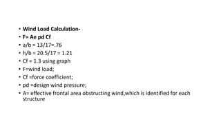
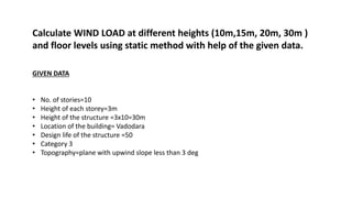
WIND LOAD
SANDHYA – 1AN15AT025
SPURTHI – 1AN15AT029
WIND
• Wind is a moving mass of air . Buildings and other structures represent
obstacles that deflect or impede the wind , covering the kinetic energy of the
moving air mass into the potential energy of pressure.
• Wind loads result from the forces exerted by the kinetic energy of the moving
mass of air , which can produce a combination of direct pressure , negative
pressure or suction , and drag forces on buildings and other obstactles in its
path.
• Wind forces are typically assumed to be applied normal , or perpendicular ,
to the affected surfaces of the building.
• Wind pressure increases as a function of wind velocity. The average mean
wind velocity for any particular area , measured over a long period of time ,
generally increases with height . The rate of increase of the mean velocity is
also a function of the ground roughness and the interference offered by
surrounding objects that include other buildings , vegetation , and land
forms.
Load acting on high rise buildings
Vertical loads:
DEAD LOADS
LIVE LOADS
Lateral loads:
SEISMIC LOAD (EARTHQUAKE LOAD)
WIND LOAD
Variation of Wind Velocity with Height
• Variation of Wind Velocity with
Height-Near the earth’s
surface, the motion is
opposed, and the wind speed
reduced , by the surface
friction.
• At the surface , the wind
speed reduces to zero and
then begins to increase with
height , and at some height,
known as the gradient height,
the motion may be considered
to be free of the earth’s
frictional influence and will
attain its ‘gradient velocity’.
Gradient Height 300 m for flat
ground& 550 m for very rough
terrain
• Wind Effects on Structures Wind effects on structures can be classified
as ‘Static’ and ‘Dynamic’.
• Static-Static wind effect primarily causes elastic bending and twisting of
structure.
• Dynamic for tall, long span and slender structures a ‘dynamic analysis’
of the structure is essential . Wind gusts cause fluctuating forces on the
structure which induce large dynamic motions , including oscillations.
Design wind speed – Vz=Vb.K1.K2.K3
Vz =Design wind speed at any height z inm/s;
K1= Probability Factor (K1=1.06 For Important Buildings
of Life 100 years)
K2= Terrain, Height and Structure sizefactor (Varies for
Height)
K3= Topography Factor)
Design Wind Pressure Pz
Pz = 0.6 ×Vz x Vz N/m2
Design wind speed
Value of K2 From Table 2 Of IS 875- Part3
• Wind Load Calculation-
• F= Ae pd Cf
• a/b = 13/17=.76
• h/b = 20.5/17 = 1.21
• Cf = 1.3 using graph
• F=wind load;
• Cf =force coefficient;
• pd =design wind pressure;
• A= effective frontal area obstructing wind,which is identified for each
structure
GIVEN DATA
• No. of stories=10
• Height of each storey=3m
• Height of the structure =3x10=30m
• Location of the building= Vadodara
• Design life of the structure =50
• Category 3
• Topography=plane with upwind slope less than 3 deg
Calculate WIND LOAD at different heights (10m,15m, 20m, 30m )
and floor levels using static method with help of the given data.
PLAN ELEVATION
15M
30M
STEP 1
CALCULATING DESIGN WIND SPEED
DESIGN WIND SPEED
Design wind speed – Vz = Vb.K1.K2.K3
Vz =Design wind speed at any height z in m/s;
• Vb = Basic wind speed at any height z in m/s;
• K1= Probability Factor
• K2= Terrain, Height and Structure sizefactor (Varies for Height)
• K3= Topography Factor
BASIC WIND SPEED (Vb)
As per IS 875 part 3
Clause 5.2
Vb VALUE = 44m/s , ACCORDING TO GIVEN DATA
K1 (PROBABILITY FACTOR)
As per IS 875 part 3
Table 1 Clause 5.3.1
K1 VALUE = 1, ACCORDING TO
GIVEN DATA
DIMENSIONS OF THE BUILDING
• L=24M
• B=15M MAX DIMENSION H=30M
• H=30M
K2 VALUE , ACCORDING TO GIVEN DATA
HEIGHT K2 VALUE FOR TERRAIN
CATEGORY 3
10 0.88
15 0.94
20 0.98
30 1.03
K2 ( TERRAIN,HEIGHT
AND STRUCTURE SIZE
FACTOR)
As per IS 875 part 3
Table 2 Clause 5.3.2.2
• IF DEG IS LESS THAN 3
THEN K3=1
• IF DEG IS GREATER THAN 3
THEN K3= 1 TO 1.36
K3=1, ACCORDING TO GIVEN DATA
K3 ( TOPOGRAPHY FACTOR )
UPWIND SLOPE DEGREE
As per IS 875 part 3
Clause 5.3.3.1
Design wind speed – Vz = Vb.K1.K2.K3
Vb VALUE = 44m/s , ACCORDING TO GIVEN DATA
K1 VALUE = 1, ACCORDING TO GIVEN DATA
K2 VALUE , ACCORDING TO GIVEN DATA
K3=1, ACCORDING TO GIVEN DATA
HEIGHT K2 VALUE FOR TERRAIN
CATEGORY 3
10 0.88
15 0.94
20 0.98
30 1.03
HEIGHT VZ VALUE (mls)
10 38.72
15 41.36
20 43.12
30 45.32
Vz = 44 X 1 X K2 X 1
STEP 2
CALCULATING DESIGN WIND PRESSURE
Pz = 0.6 ×Vz x Vz N/m2
CALCULATING DESIGN WIND PRESSURE
HEIGHT VZ VALUE (m/s)
10 38.72
15 41.36
20 43.12
30 45.32
HEIGHT Vz VALUE (m/s) Pz VALUE
(N/m2)
10 38.72 899.54
15 41.36 1026.38
20 43.12 1115.60
30 45.32 1232.34
STEP 3
CALCULATING DESIGN WIND LOAD
1.CALCULATING DESIGN WIND LOAD
Wind Load Calculation- F= Ae x Pd x Cf
• F=wind load
• Ae= effective frontal area obstructing wind, which is identified for
each structure
• Cf =force coefficient
• pd =design wind pressure
FIND H/B RATIO AND CHECK IF IT IS GREATER OR LESSER THEN 1
( HELPS TO DECIDE WHICH GRAPH TO FIND Cf)
HEIGHT (H)= 30
LENGTH (B) = 24
BREADTH (A) = 15
A / B = 0.62
H/B = 30 / 24 = 1.25
1.25 > 1
USE GRAPH 6A
FINDING Cf VALUE USING GRAPH
As per IS 875 part 3
Clause 5.2
IF H/b VALUE IS GREATER
THAN OR EQUAL TO 1
THEN USE GRAPH 6A
IF H/b VALUE IS LESSER
THAN 1 THEN USE GRAPH
6B
A / B = 0.62
H/B = 1.25
Cf=1.2
2.CALCULATING VALUE OF FRONTAL AREA (Ae)
Ae= effective frontal area obstructing wind, which is identified
for each structure
Here, we are calculating load per unit area
Therefore, frontal area= 1 x 6 (shortest span between columns )
Ae = 1 x 6 =6 m2
PLAN ELEVATION
15M
30M
2.CALCULATING VALUE OF DESIGN LOAD AT DIFFERENT HEIGHT
HEIGHT Pz DESIGN PRESSURE F = Ae X Cf X Pz
( in N/m)
F = WIND LOAD
( in KN/m )
0-10 899.54 6584.6 6.58
10-15 1026.38 7513.10 7.513
15-20 1115.60 8166.19 8.166
20-30 1232.34 9020.72 9.020
30m
20m
10m
0m
15m
6.58 Km/m
7.513 Km/m
8.166 Km/m
9.02 Km/m
10
9
8
7
6
5
4
3
2
1
019.74
19.74
19.74
19.74
21.39
22.53
23.7
24.75
25.5
26.28
27.06STOREY
NUMBER
LOADING
LEVEL
HEIGHT OF
EACH FLOOR
DESIGN
FORCE KN/m
FORCE AT EACH
STOREY (KN)
10 27-30 3 9.02 27.06
9 24-27 3 8.76 26.28
8 21-24 3 8.50 25.5
7 18-21 3 8.25 24.75
6 15-18 3 7.90 23.7
5 12-15 3 7.51 22.53
4 9-12 3 7.13 21.39
3 6-9 3 6.58 19.74
2 3-6 3 6.58 19.74
1 0-3 3 6.58 19.74
10
9
8
7
6
5
4
3
2
1
019.74
19.74
19.74
19.74
21.39
22.53
23.7
24.75
25.5
26.28
27.0630m
20m
10m
0m
15m
6.58 Km/m
7.513 Km/m
8.166 Km/m
9.02 Km/m
THANK YOU

Wind load

  • 1.
    WIND LOAD SANDHYA –1AN15AT025 SPURTHI – 1AN15AT029
  • 2.
    WIND • Wind isa moving mass of air . Buildings and other structures represent obstacles that deflect or impede the wind , covering the kinetic energy of the moving air mass into the potential energy of pressure. • Wind loads result from the forces exerted by the kinetic energy of the moving mass of air , which can produce a combination of direct pressure , negative pressure or suction , and drag forces on buildings and other obstactles in its path. • Wind forces are typically assumed to be applied normal , or perpendicular , to the affected surfaces of the building. • Wind pressure increases as a function of wind velocity. The average mean wind velocity for any particular area , measured over a long period of time , generally increases with height . The rate of increase of the mean velocity is also a function of the ground roughness and the interference offered by surrounding objects that include other buildings , vegetation , and land forms.
  • 10.
    Load acting onhigh rise buildings Vertical loads: DEAD LOADS LIVE LOADS Lateral loads: SEISMIC LOAD (EARTHQUAKE LOAD) WIND LOAD
  • 11.
    Variation of WindVelocity with Height • Variation of Wind Velocity with Height-Near the earth’s surface, the motion is opposed, and the wind speed reduced , by the surface friction. • At the surface , the wind speed reduces to zero and then begins to increase with height , and at some height, known as the gradient height, the motion may be considered to be free of the earth’s frictional influence and will attain its ‘gradient velocity’. Gradient Height 300 m for flat ground& 550 m for very rough terrain
  • 12.
    • Wind Effectson Structures Wind effects on structures can be classified as ‘Static’ and ‘Dynamic’. • Static-Static wind effect primarily causes elastic bending and twisting of structure. • Dynamic for tall, long span and slender structures a ‘dynamic analysis’ of the structure is essential . Wind gusts cause fluctuating forces on the structure which induce large dynamic motions , including oscillations.
  • 14.
    Design wind speed– Vz=Vb.K1.K2.K3 Vz =Design wind speed at any height z inm/s; K1= Probability Factor (K1=1.06 For Important Buildings of Life 100 years) K2= Terrain, Height and Structure sizefactor (Varies for Height) K3= Topography Factor) Design Wind Pressure Pz Pz = 0.6 ×Vz x Vz N/m2 Design wind speed Value of K2 From Table 2 Of IS 875- Part3
  • 15.
    • Wind LoadCalculation- • F= Ae pd Cf • a/b = 13/17=.76 • h/b = 20.5/17 = 1.21 • Cf = 1.3 using graph • F=wind load; • Cf =force coefficient; • pd =design wind pressure; • A= effective frontal area obstructing wind,which is identified for each structure
  • 17.
    GIVEN DATA • No.of stories=10 • Height of each storey=3m • Height of the structure =3x10=30m • Location of the building= Vadodara • Design life of the structure =50 • Category 3 • Topography=plane with upwind slope less than 3 deg Calculate WIND LOAD at different heights (10m,15m, 20m, 30m ) and floor levels using static method with help of the given data.
  • 18.
  • 19.
  • 20.
    DESIGN WIND SPEED Designwind speed – Vz = Vb.K1.K2.K3 Vz =Design wind speed at any height z in m/s; • Vb = Basic wind speed at any height z in m/s; • K1= Probability Factor • K2= Terrain, Height and Structure sizefactor (Varies for Height) • K3= Topography Factor
  • 21.
    BASIC WIND SPEED(Vb) As per IS 875 part 3 Clause 5.2 Vb VALUE = 44m/s , ACCORDING TO GIVEN DATA
  • 22.
    K1 (PROBABILITY FACTOR) Asper IS 875 part 3 Table 1 Clause 5.3.1 K1 VALUE = 1, ACCORDING TO GIVEN DATA
  • 23.
    DIMENSIONS OF THEBUILDING • L=24M • B=15M MAX DIMENSION H=30M • H=30M K2 VALUE , ACCORDING TO GIVEN DATA HEIGHT K2 VALUE FOR TERRAIN CATEGORY 3 10 0.88 15 0.94 20 0.98 30 1.03 K2 ( TERRAIN,HEIGHT AND STRUCTURE SIZE FACTOR) As per IS 875 part 3 Table 2 Clause 5.3.2.2
  • 25.
    • IF DEGIS LESS THAN 3 THEN K3=1 • IF DEG IS GREATER THAN 3 THEN K3= 1 TO 1.36 K3=1, ACCORDING TO GIVEN DATA K3 ( TOPOGRAPHY FACTOR ) UPWIND SLOPE DEGREE As per IS 875 part 3 Clause 5.3.3.1
  • 26.
    Design wind speed– Vz = Vb.K1.K2.K3 Vb VALUE = 44m/s , ACCORDING TO GIVEN DATA K1 VALUE = 1, ACCORDING TO GIVEN DATA K2 VALUE , ACCORDING TO GIVEN DATA K3=1, ACCORDING TO GIVEN DATA HEIGHT K2 VALUE FOR TERRAIN CATEGORY 3 10 0.88 15 0.94 20 0.98 30 1.03 HEIGHT VZ VALUE (mls) 10 38.72 15 41.36 20 43.12 30 45.32 Vz = 44 X 1 X K2 X 1
  • 27.
  • 28.
    Pz = 0.6×Vz x Vz N/m2 CALCULATING DESIGN WIND PRESSURE HEIGHT VZ VALUE (m/s) 10 38.72 15 41.36 20 43.12 30 45.32 HEIGHT Vz VALUE (m/s) Pz VALUE (N/m2) 10 38.72 899.54 15 41.36 1026.38 20 43.12 1115.60 30 45.32 1232.34
  • 29.
  • 30.
    1.CALCULATING DESIGN WINDLOAD Wind Load Calculation- F= Ae x Pd x Cf • F=wind load • Ae= effective frontal area obstructing wind, which is identified for each structure • Cf =force coefficient • pd =design wind pressure
  • 31.
    FIND H/B RATIOAND CHECK IF IT IS GREATER OR LESSER THEN 1 ( HELPS TO DECIDE WHICH GRAPH TO FIND Cf) HEIGHT (H)= 30 LENGTH (B) = 24 BREADTH (A) = 15 A / B = 0.62 H/B = 30 / 24 = 1.25 1.25 > 1 USE GRAPH 6A FINDING Cf VALUE USING GRAPH As per IS 875 part 3 Clause 5.2 IF H/b VALUE IS GREATER THAN OR EQUAL TO 1 THEN USE GRAPH 6A IF H/b VALUE IS LESSER THAN 1 THEN USE GRAPH 6B
  • 32.
    A / B= 0.62 H/B = 1.25 Cf=1.2
  • 33.
    2.CALCULATING VALUE OFFRONTAL AREA (Ae) Ae= effective frontal area obstructing wind, which is identified for each structure Here, we are calculating load per unit area Therefore, frontal area= 1 x 6 (shortest span between columns ) Ae = 1 x 6 =6 m2
  • 34.
  • 35.
    2.CALCULATING VALUE OFDESIGN LOAD AT DIFFERENT HEIGHT HEIGHT Pz DESIGN PRESSURE F = Ae X Cf X Pz ( in N/m) F = WIND LOAD ( in KN/m ) 0-10 899.54 6584.6 6.58 10-15 1026.38 7513.10 7.513 15-20 1115.60 8166.19 8.166 20-30 1232.34 9020.72 9.020
  • 36.
  • 37.
    10 9 8 7 6 5 4 3 2 1 019.74 19.74 19.74 19.74 21.39 22.53 23.7 24.75 25.5 26.28 27.06STOREY NUMBER LOADING LEVEL HEIGHT OF EACH FLOOR DESIGN FORCEKN/m FORCE AT EACH STOREY (KN) 10 27-30 3 9.02 27.06 9 24-27 3 8.76 26.28 8 21-24 3 8.50 25.5 7 18-21 3 8.25 24.75 6 15-18 3 7.90 23.7 5 12-15 3 7.51 22.53 4 9-12 3 7.13 21.39 3 6-9 3 6.58 19.74 2 3-6 3 6.58 19.74 1 0-3 3 6.58 19.74
  • 38.
  • 39.