Downloaded 230 times


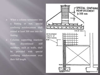
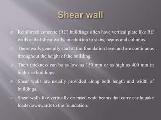
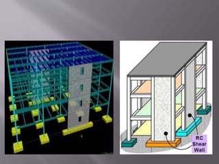

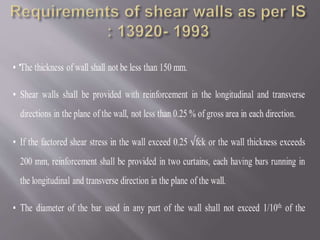
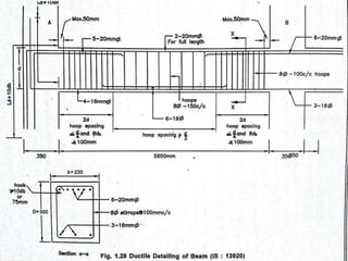
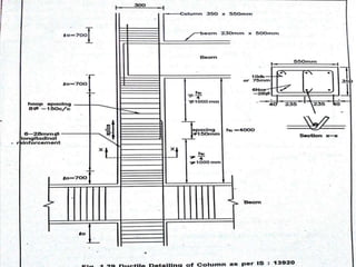

The document discusses ductility and ductile detailing in reinforced concrete structures. It states that structures should be designed to have lateral strength, deformability, and ductility to resist earthquakes with limited damage and no collapse. Ductility allows structures to develop their full strength through internal force redistribution. Detailing of reinforcement is important to avoid brittle failure and induce ductile behavior by allowing steel to yield in a controlled manner. Shear walls are also discussed as vertical reinforced concrete elements that help structures resist earthquake loads in a ductile manner.


