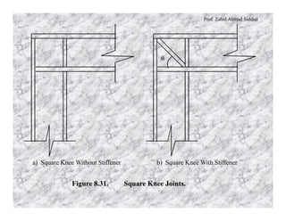
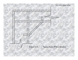
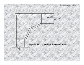
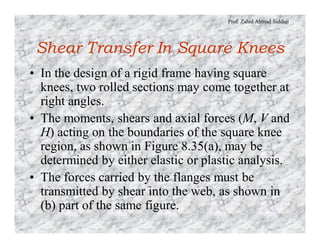
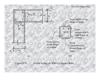
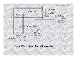
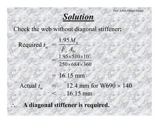
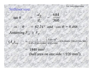
Prof. Zahid Ahmad Siddiqi
MOMENT CONNECTIONS
Rigid Frame Knees
• These are a type of fully restrained (FR) or
moment connection.
• In the design of rigid frames the safe transmission
of load at the junction of beam and column is of
great importance.
• When members join with their webs lying in the
plane of the frame, the junction is frequently
referred to as a knee joint.
Prof. Zahid Ahmad Siddiqi
Typical knee joints are:
Square Knees, with and without a diagonal
stiffener, are shown in Figure 8.31.
Column or beam section may be continued
through the junction.
Prof. Zahid Ahmad Siddiqi
q
a) Square Knee Without Stiffener b) Square Knee With Stiffener
Figure 8.31. Square Knee Joints.
Prof. Zahid Ahmad Siddiqi
Square Knee With a Bracket is shown in
Figure 8.32.
This type of joint may resist large negative
moments reducing the size of the beam and
the column.
Prof. Zahid Ahmad Siddiqi
Figure 8.32. Square Knee With a Bracket.
Prof. Zahid Ahmad Siddiqi
Straight Haunched Knee is a modification
of the square knee with a bracket.
The beam and column sections are
discontinued short of the connection.
The haunch consists of a separate plate
reinforced by perpendicular stiffeners (see
Figure 8.33).
Prof. Zahid Ahmad Siddiqi
Figure 8.33. Straight Haunched Knee.
Prof. Zahid Ahmad Siddiqi
Curved Haunched Knee is similar to a
straight haunched knee with the difference
of having a curved inner profile, as shown
in Figure 8.34.
Figure 8.34. Curved Haunched Knee.
Prof. Zahid Ahmad Siddiqi
For haunched knees, variable moment of
inertia has to be considered with the
knees for both beams and column to
perform analysis.
To be adequately designed, a knee
connection must satisfy the following
requirements:
Prof. Zahid Ahmad Siddiqi
1. The end moment between the beam and the
column must be transferred.
2. The beam end shear must safely go to the
column.
3. The shear at the top of the column should be
transferred into the beam.
4. The joint must deform in a manner consistent
with the analysis by which moments and shears
are determined.
5. If a plastic hinge associated with the failure
mechanism is expected to form at or near the
knee, adequate rotation capacity must be built
into the connections.
Prof. Zahid Ahmad Siddiqi
• Square knees have the greatest plastic rotation
capacity but this flexibility increases the service
load deflections as they deform elastically the
most under the loads.
• Curved knees are the most stiff but have the
least rotation capacity.
• Since straight tapered knees provide reasonable
stiffness along with adequate rotation capacity,
in addition to the fact that they are cheaper than
curved haunches to fabricate, the straight
haunched knees are more commonly used.
Prof. Zahid Ahmad Siddiqi
Shear Transfer In Square Knees
• In the design of a rigid frame having square
knees, two rolled sections may come together at
right angles.
• The moments, shears and axial forces (M, V and
H) acting on the boundaries of the square knee
region, as shown in Figure 8.35(a), may be
determined by either elastic or plastic analysis.
• The forces carried by the flanges must be
transmitted by shear into the web, as shown in
(b) part of the same figure.
Prof. Zahid Ahmad Siddiqi
(a)
WEB
BA
D C
Tc
Tb
From tension
in left flange
of column
From
compression in
bottom flange of
beam
From tension in top
flange of beam
From
compression in
right flange of
column
(b)
Cb
Tb
db
»dc
Cc
Tc
BA
D C
M H
M
H
V
V
Figure 8.35. Forces Acting on Web of a Square Knee.
Prof. Zahid Ahmad Siddiqi
Assuming all bending moment to be carried
by the flanges, and approximating the
distance between flange centroids as 0.95
db, the flange force is:
Tu = Tb =
b
u
d95.0
M
The nominal shear strength of the web in
across the edge AB is:
Vn = Vab = ty tw dc
where ty = 0.6 Fy and fn = 0.9
Prof. Zahid Ahmad Siddiqi
For design, f Vn = Tu,
which gives:
fn (0.6 Fy) tw dc =
b
u
d
M
95.0
Req. tw without diagonal stiffener =
=
cby
u
ddF
M95.1
bcy
u
AF
M95.1
where Abc = the planner area within the knee
= db dc.
Prof. Zahid Ahmad Siddiqi
Diagonal Stiffeners
• In a rigid frame knee, the required web
thickness usually exceeds that provided by a W-
section and reinforcement is required.
• A doubler plate is sometimes used to thicken the
web region, which is not a general practical
solution because of the difficulty of making the
attachment to the column web.
• Usually, a pair of diagonal stiffeners is the best
solution, as shown in Figure 8.37.
Prof. Zahid Ahmad Siddiqi
Cst cos q
Cst
q
A B
D C
Figure 8.37. Web of a Square Knee Connection With a Stiffener.
Prof. Zahid Ahmad Siddiqi
• Stiffener resistive compressive force
= Cst
= Ast fc Fcr
• Applied shear on the web ( Figure 8.35 (b))
= Tu
• When diagonal stiffeners are used, the
horizontal component Cst´cosq of the
stiffener force participates in resisting the
shear with the web.
Prof. Zahid Ahmad Siddiqi
SFx = 0 Þ
Tu = Vab + Cst cos q
= fn (0.60 Fy) tw dc + Ast fcFcr cos q
b
u
d95.0
M
Ast, req = ( ) ú
û
ù
ê
ë
é
- cwy
b
u
crc
dtF
d
M
F
60.0
95.0cos
1
nf
qf
where fn = 0.90 for any yield limit state
like in shear
fc = 0.85 for compression
elements
Fcr = compression limit state stress
Prof. Zahid Ahmad Siddiqi
Example 8.6
Design the square knee connection given in
Figure 8.38 to join a W690 ´ 140 girder to a
W360 ´ 110 column. The factored moment
Mu to be carried through the joint is 510 kN-
m. Use A36 steel and E70 electrodes with
SMAW.
Prof. Zahid Ahmad Siddiqi
285 kN
510 kN-m
67 kN
285 kN
67 kN
510 kN-m
B
A
D
C
q
W360 ´ 110
W690 ´ 140
db = 684 mm
(tw)b = 12.4 mm
tf = 18.9 mm
bf = 254 mm
dc = 360 mm
(tw)c = 11.4 mm
tf = 19.9 mm
bf = 256 mm
Figure 8.38. Square Knee of Example 8.6.
Prof. Zahid Ahmad Siddiqi
Solution
Check the web without diagonal stiffener:
Required tw =
=
= 16.15 mm
bcy
u
AF
M95.1
360684250
1051095.1 6
´´
´´
Actual tw = 12.4 mm for W690 ´ 140
< 16.15 mm
 A diagonal stiffener is required.
Prof. Zahid Ahmad Siddiqi
Stiffener size:
tan q = =
Þ q = 62.24° and cos q = 0.466
c
b
d
d
360
684
Assuming Fcr @ Fy,
(Ast)req = ú
ú
û
ù
ê
ê
ë
é
´´´´-
´
´
´´
3604.1225060.09.0
68495.0
10510
466.025085.0
1 6
= 1840 mm2
(half area on one side = 920 mm2)
Prof. Zahid Ahmad Siddiqi
Using tst = 12 mm ; bst = 77 mm
say 80 mm
l = = 6.67 < lr = 15.8 OK
Size of stiffener:2 PL s 12 ´ 80 on both sides of
the web
Strength of the stiffener acting as a column:
Overall width of stiffener = b = 2 bst + tw
= 2 ´ 80 + 12.4 = 172.4 mm
Prof. Zahid Ahmad Siddiqi
r = = = 0.289 b
= 49.82 mm
( )
bt
12bt
st
3
st ( )b
12
1
= = @ 16
 fc Fcr = 209.64 MPa
r
KL
r
cosdc q
8249
4660360
.
.
This means that Fcr is equal to 246.6 MPa,
which is very close to the assumed value of
Fcr = Fy.
Prof. Zahid Ahmad Siddiqi
Determine the fillet weld size along length AB.
The weld must transmit the factored flange
force into the beam web. The maximum design
flange force that can be developed is ft Fy Af.
Flange force = ft Fy Af = 0.90 ´ 250 ´ 19.9 ´
256/1000 = 1146.24 kN
The design strength of fillet welds along both
sides of web is:
f Rnw = 2(0.75 ´ 0.707 ´ tw ´ 0.6 ´ 495/1000)
= 0.315 tw kN/mm
Prof. Zahid Ahmad Siddiqi
Available length for weld = db – 2 tf
= 684 – 2 ´ 18.9 = 646.2 mm
 0.315 tw (646.2) = 1146.24
tw = 6 mm
Use 6 mm thick E70 fillet weld along length
AB (both sides of girder web)
Prof. Zahid Ahmad Siddiqi
Determine fillet weld size along length BC.
The connection of the column web to the beam
flange must carry the force resulting from
flexure and axial load, combined with the
shear acting simultaneously on the weld.
The forces transferred through this weld may
conservatively be estimated as follows:
Tensile component = ft Fy tw
= 0.9 ´ 250 ´ 12.4/1000 = 2.79 kN/mm
Prof. Zahid Ahmad Siddiqi
Shear component = =
= 0.21 kN/mm
fc
u
td
V
2- 9.192360
67
´-
Resultant loading = = 2.80 kN/mm22
21.079.2 +
Required tw = @ 9 mm315.0
80.2
Use 9 mm thick E70 fillet weld along length BC
on both sides of girder web
Prof. Zahid Ahmad Siddiqi
Weld required along diagonal stiffeners is
designed next. This weld must develop the
required stiffener strength.
f Cs = f Fy Ast
= 0.9 ´ 250 ´ 2 ´ 12 ´ 80/1000 = 432 kN
Required tw = = 1 mm
say 6 mm
( )
495.06.0707.075.04
466.0360432
´´´´
Use 6mm thick E70 fillet weld along diagonal
stiffener on both sides of girder web
Prof. Zahid Ahmad Siddiqi
Determine the required length of the stiffener CD:
The design strength based on local web yielding from
the inside column flange at C is:
Pbf = f (5 k + tfb) Fyc twc
= 1.0(5 ´ 37 + 18.9) ´ 250 ´ 11.4/1000
= 581.12 kN
Flange force as calculated earlier = 1146.24 kN
The force is greater than capacity of the web alone and
diagonal stiffener is already resisting other forces.
Hence, vertical stiffener is required at C.
Prof. Zahid Ahmad Siddiqi
Stiffener along CD:
Required Ast =
= 1256 mm2 per plate
2
112581241146
´
-
yF
..
f
Width available = =
= 120.8 mm say 110 mm
2
wbfb tb -
2
4.12254-
Required tst = @ 12 mm
110
1256
l = = 9.17 < lp = 10.8 OK12
110
Prof. Zahid Ahmad Siddiqi
Length of stiffener = @ 325 mm2
2 ftd -
Use 2 PL s – 12 ´ 110 ´ 325, tapered from full
width at C to zero at D

Steel strucure lec # (21)

  • 1.
    Prof. Zahid AhmadSiddiqi MOMENT CONNECTIONS Rigid Frame Knees • These are a type of fully restrained (FR) or moment connection. • In the design of rigid frames the safe transmission of load at the junction of beam and column is of great importance. • When members join with their webs lying in the plane of the frame, the junction is frequently referred to as a knee joint.
  • 2.
    Prof. Zahid AhmadSiddiqi Typical knee joints are: Square Knees, with and without a diagonal stiffener, are shown in Figure 8.31. Column or beam section may be continued through the junction.
  • 3.
    Prof. Zahid AhmadSiddiqi q a) Square Knee Without Stiffener b) Square Knee With Stiffener Figure 8.31. Square Knee Joints.
  • 4.
    Prof. Zahid AhmadSiddiqi Square Knee With a Bracket is shown in Figure 8.32. This type of joint may resist large negative moments reducing the size of the beam and the column.
  • 5.
    Prof. Zahid AhmadSiddiqi Figure 8.32. Square Knee With a Bracket.
  • 6.
    Prof. Zahid AhmadSiddiqi Straight Haunched Knee is a modification of the square knee with a bracket. The beam and column sections are discontinued short of the connection. The haunch consists of a separate plate reinforced by perpendicular stiffeners (see Figure 8.33).
  • 7.
    Prof. Zahid AhmadSiddiqi Figure 8.33. Straight Haunched Knee.
  • 8.
    Prof. Zahid AhmadSiddiqi Curved Haunched Knee is similar to a straight haunched knee with the difference of having a curved inner profile, as shown in Figure 8.34. Figure 8.34. Curved Haunched Knee.
  • 9.
    Prof. Zahid AhmadSiddiqi For haunched knees, variable moment of inertia has to be considered with the knees for both beams and column to perform analysis. To be adequately designed, a knee connection must satisfy the following requirements:
  • 10.
    Prof. Zahid AhmadSiddiqi 1. The end moment between the beam and the column must be transferred. 2. The beam end shear must safely go to the column. 3. The shear at the top of the column should be transferred into the beam. 4. The joint must deform in a manner consistent with the analysis by which moments and shears are determined. 5. If a plastic hinge associated with the failure mechanism is expected to form at or near the knee, adequate rotation capacity must be built into the connections.
  • 11.
    Prof. Zahid AhmadSiddiqi • Square knees have the greatest plastic rotation capacity but this flexibility increases the service load deflections as they deform elastically the most under the loads. • Curved knees are the most stiff but have the least rotation capacity. • Since straight tapered knees provide reasonable stiffness along with adequate rotation capacity, in addition to the fact that they are cheaper than curved haunches to fabricate, the straight haunched knees are more commonly used.
  • 12.
    Prof. Zahid AhmadSiddiqi Shear Transfer In Square Knees • In the design of a rigid frame having square knees, two rolled sections may come together at right angles. • The moments, shears and axial forces (M, V and H) acting on the boundaries of the square knee region, as shown in Figure 8.35(a), may be determined by either elastic or plastic analysis. • The forces carried by the flanges must be transmitted by shear into the web, as shown in (b) part of the same figure.
  • 13.
    Prof. Zahid AhmadSiddiqi (a) WEB BA D C Tc Tb From tension in left flange of column From compression in bottom flange of beam From tension in top flange of beam From compression in right flange of column (b) Cb Tb db »dc Cc Tc BA D C M H M H V V Figure 8.35. Forces Acting on Web of a Square Knee.
  • 14.
    Prof. Zahid AhmadSiddiqi Assuming all bending moment to be carried by the flanges, and approximating the distance between flange centroids as 0.95 db, the flange force is: Tu = Tb = b u d95.0 M The nominal shear strength of the web in across the edge AB is: Vn = Vab = ty tw dc where ty = 0.6 Fy and fn = 0.9
  • 15.
    Prof. Zahid AhmadSiddiqi For design, f Vn = Tu, which gives: fn (0.6 Fy) tw dc = b u d M 95.0 Req. tw without diagonal stiffener = = cby u ddF M95.1 bcy u AF M95.1 where Abc = the planner area within the knee = db dc.
  • 16.
    Prof. Zahid AhmadSiddiqi Diagonal Stiffeners • In a rigid frame knee, the required web thickness usually exceeds that provided by a W- section and reinforcement is required. • A doubler plate is sometimes used to thicken the web region, which is not a general practical solution because of the difficulty of making the attachment to the column web. • Usually, a pair of diagonal stiffeners is the best solution, as shown in Figure 8.37.
  • 17.
    Prof. Zahid AhmadSiddiqi Cst cos q Cst q A B D C Figure 8.37. Web of a Square Knee Connection With a Stiffener.
  • 18.
    Prof. Zahid AhmadSiddiqi • Stiffener resistive compressive force = Cst = Ast fc Fcr • Applied shear on the web ( Figure 8.35 (b)) = Tu • When diagonal stiffeners are used, the horizontal component Cst´cosq of the stiffener force participates in resisting the shear with the web.
  • 19.
    Prof. Zahid AhmadSiddiqi SFx = 0 Þ Tu = Vab + Cst cos q = fn (0.60 Fy) tw dc + Ast fcFcr cos q b u d95.0 M Ast, req = ( ) ú û ù ê ë é - cwy b u crc dtF d M F 60.0 95.0cos 1 nf qf where fn = 0.90 for any yield limit state like in shear fc = 0.85 for compression elements Fcr = compression limit state stress
  • 20.
    Prof. Zahid AhmadSiddiqi Example 8.6 Design the square knee connection given in Figure 8.38 to join a W690 ´ 140 girder to a W360 ´ 110 column. The factored moment Mu to be carried through the joint is 510 kN- m. Use A36 steel and E70 electrodes with SMAW.
  • 21.
    Prof. Zahid AhmadSiddiqi 285 kN 510 kN-m 67 kN 285 kN 67 kN 510 kN-m B A D C q W360 ´ 110 W690 ´ 140 db = 684 mm (tw)b = 12.4 mm tf = 18.9 mm bf = 254 mm dc = 360 mm (tw)c = 11.4 mm tf = 19.9 mm bf = 256 mm Figure 8.38. Square Knee of Example 8.6.
  • 22.
    Prof. Zahid AhmadSiddiqi Solution Check the web without diagonal stiffener: Required tw = = = 16.15 mm bcy u AF M95.1 360684250 1051095.1 6 ´´ ´´ Actual tw = 12.4 mm for W690 ´ 140 < 16.15 mm A diagonal stiffener is required.
  • 23.
    Prof. Zahid AhmadSiddiqi Stiffener size: tan q = = Þ q = 62.24° and cos q = 0.466 c b d d 360 684 Assuming Fcr @ Fy, (Ast)req = ú ú û ù ê ê ë é ´´´´- ´ ´ ´´ 3604.1225060.09.0 68495.0 10510 466.025085.0 1 6 = 1840 mm2 (half area on one side = 920 mm2)
  • 24.
    Prof. Zahid AhmadSiddiqi Using tst = 12 mm ; bst = 77 mm say 80 mm l = = 6.67 < lr = 15.8 OK Size of stiffener:2 PL s 12 ´ 80 on both sides of the web Strength of the stiffener acting as a column: Overall width of stiffener = b = 2 bst + tw = 2 ´ 80 + 12.4 = 172.4 mm
  • 25.
    Prof. Zahid AhmadSiddiqi r = = = 0.289 b = 49.82 mm ( ) bt 12bt st 3 st ( )b 12 1 = = @ 16 fc Fcr = 209.64 MPa r KL r cosdc q 8249 4660360 . . This means that Fcr is equal to 246.6 MPa, which is very close to the assumed value of Fcr = Fy.
  • 26.
    Prof. Zahid AhmadSiddiqi Determine the fillet weld size along length AB. The weld must transmit the factored flange force into the beam web. The maximum design flange force that can be developed is ft Fy Af. Flange force = ft Fy Af = 0.90 ´ 250 ´ 19.9 ´ 256/1000 = 1146.24 kN The design strength of fillet welds along both sides of web is: f Rnw = 2(0.75 ´ 0.707 ´ tw ´ 0.6 ´ 495/1000) = 0.315 tw kN/mm
  • 27.
    Prof. Zahid AhmadSiddiqi Available length for weld = db – 2 tf = 684 – 2 ´ 18.9 = 646.2 mm 0.315 tw (646.2) = 1146.24 tw = 6 mm Use 6 mm thick E70 fillet weld along length AB (both sides of girder web)
  • 28.
    Prof. Zahid AhmadSiddiqi Determine fillet weld size along length BC. The connection of the column web to the beam flange must carry the force resulting from flexure and axial load, combined with the shear acting simultaneously on the weld. The forces transferred through this weld may conservatively be estimated as follows: Tensile component = ft Fy tw = 0.9 ´ 250 ´ 12.4/1000 = 2.79 kN/mm
  • 29.
    Prof. Zahid AhmadSiddiqi Shear component = = = 0.21 kN/mm fc u td V 2- 9.192360 67 ´- Resultant loading = = 2.80 kN/mm22 21.079.2 + Required tw = @ 9 mm315.0 80.2 Use 9 mm thick E70 fillet weld along length BC on both sides of girder web
  • 30.
    Prof. Zahid AhmadSiddiqi Weld required along diagonal stiffeners is designed next. This weld must develop the required stiffener strength. f Cs = f Fy Ast = 0.9 ´ 250 ´ 2 ´ 12 ´ 80/1000 = 432 kN Required tw = = 1 mm say 6 mm ( ) 495.06.0707.075.04 466.0360432 ´´´´ Use 6mm thick E70 fillet weld along diagonal stiffener on both sides of girder web
  • 31.
    Prof. Zahid AhmadSiddiqi Determine the required length of the stiffener CD: The design strength based on local web yielding from the inside column flange at C is: Pbf = f (5 k + tfb) Fyc twc = 1.0(5 ´ 37 + 18.9) ´ 250 ´ 11.4/1000 = 581.12 kN Flange force as calculated earlier = 1146.24 kN The force is greater than capacity of the web alone and diagonal stiffener is already resisting other forces. Hence, vertical stiffener is required at C.
  • 32.
    Prof. Zahid AhmadSiddiqi Stiffener along CD: Required Ast = = 1256 mm2 per plate 2 112581241146 ´ - yF .. f Width available = = = 120.8 mm say 110 mm 2 wbfb tb - 2 4.12254- Required tst = @ 12 mm 110 1256 l = = 9.17 < lp = 10.8 OK12 110
  • 33.
    Prof. Zahid AhmadSiddiqi Length of stiffener = @ 325 mm2 2 ftd - Use 2 PL s – 12 ´ 110 ´ 325, tapered from full width at C to zero at D