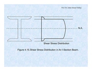
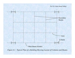
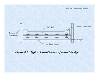
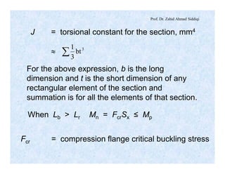
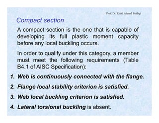
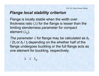
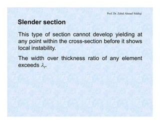
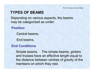
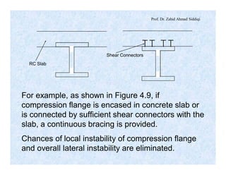
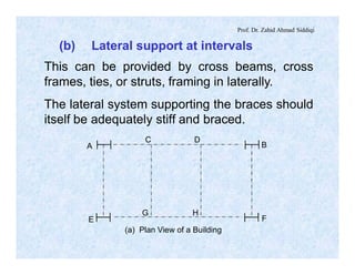
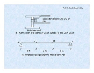
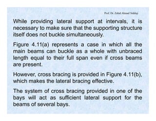
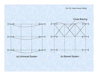
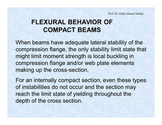
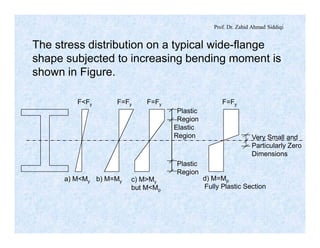
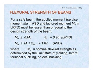
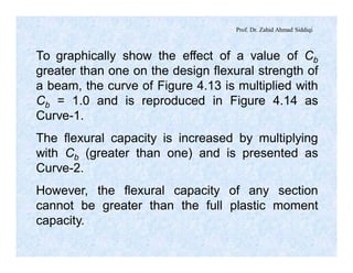
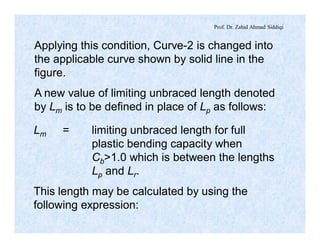
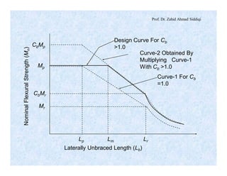
The document discusses different types of beams used in structures. It defines a beam as a structural member subjected primarily to bending. Different types of beams discussed include girders, secondary beams, joists, purlins, stringers, floor beams, girts, lintels and spandrels. Beams are classified based on their position, end conditions, fabrication method, and general span ranges. The document also covers beam analysis, including the flexure formula, stability of beam sections, and classification of beam sections as compact, non-compact and slender.

![Prof. Dr. Zahid Ahmad Siddiqi
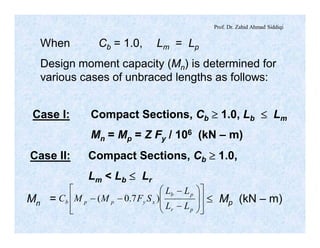
Mn = Cb [Mp – BF(Lb – Lp)] £ Mp (kN – m)
Case III: Compact Sections, Cb ³ 1.0,
Lb > Lr
For doubly symmetric I-shaped and channel
section members:
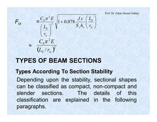
Mn = CbFcrSx £ Mp
where Fcr =
2
2
2
078.01 ÷÷
ø
ö
çç
è
æ
+
÷÷
ø
ö
çç
è
æ ts
b
ox
ts
b
b
r
L
hS
cJ
r
L
EC p
The variables rts and others are as defined earlier.](https://image.slidesharecdn.com/steelstrucurelec9-200810021459/85/Steel-strucure-lec-9-64-320.jpg)