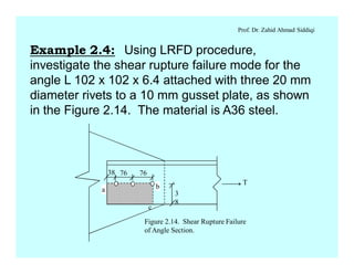
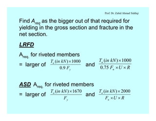
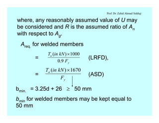
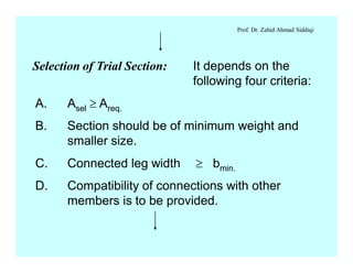
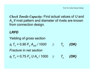
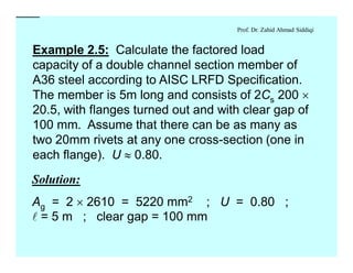
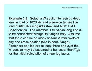
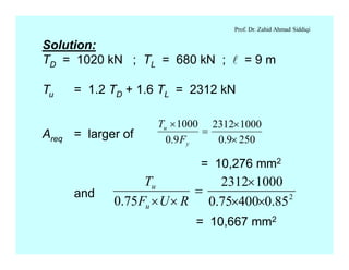
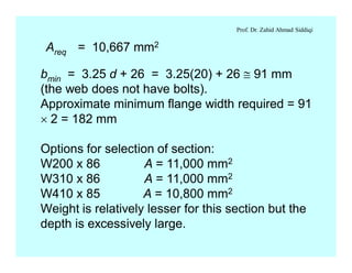
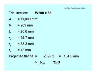
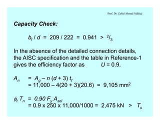
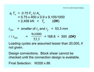
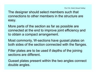
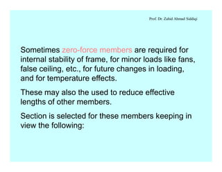
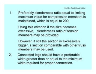
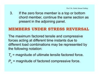
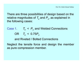
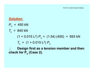
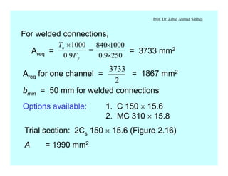
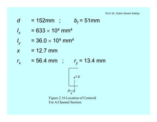
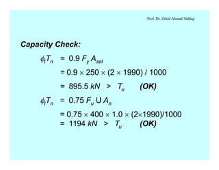
Sheet Pile Wall Design and Construction: A Practical Guide for Civil Engineer...
LRFD DESIGN OF STEEL MEMBERS
1. Prof. Dr. Zahid Ahmad Siddiqi
Example 2.4: Using LRFD procedure,
investigate the shear rupture failure mode for the
angle L 102 x 102 x 6.4 attached with three 20 mm
diameter rivets to a 10 mm gusset plate, as shown
in the Figure 2.14. The material is A36 steel.
a b
c
3
8
T
38 76 76
Figure 2.14. Shear Rupture Failure
of Angle Section.
2. Prof. Dr. Zahid Ahmad Siddiqi
Solution:
Capacity of Section:
Yielding of gross section
ft Fy Ag = 0.9 ´ 250 ´ 1250 / 1000 = 281.25 kN
Fracture in net section
ft Fu Ae = 0.75 ´ 400 ´ 0.60 ´ {1250 - (20 +
3)(6.4)}/1000
= 198.5 kN
ft Tn = 198.5 kN
3. Prof. Dr. Zahid Ahmad Siddiqi
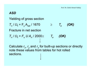
Block Shear Failure Along Path a-b-c:
Agv = (76 + 76 + 38)(6.4) = 1216 mm2
Anv = 1216 – (2.5)(20 + 3)(6.4) = 848 mm2
Ant = 243.2 – (0.5)(20 + 3)(6.4) = 169.6 mm2
Ubs = 1.0
f Rn = lesser of
1. 0.6 Fu Anv + Ubs Fu Ant
= 0.75/1000 [0.6 ´ 400 ´ 848 + 1.0 ´ 400 ´ 169.6]
= 203.52 kN
4. Prof. Dr. Zahid Ahmad Siddiqi
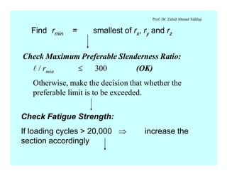
2. 0.6 Fy Agv + Ubs Fu Ant
= 0.75/1000 [0.6 ´ 250 ´ 1216 + 1.0 ´ 400
´ 169.6]
= 187.68 kN
f Rn = 187.68 kN
Hence, block shear failure is the governing limit state
and factored capacity of the member is reduced from
198.5 kN to 187.68 kN due to it.
5. Prof. Dr. Zahid Ahmad Siddiqi
DESIGN PROCEDURE/DESIGN FLOW CHART
Known Data:
Service or working loads, TD, TL, and TW, etc.
and length of member, l
Find factored tension (Tu) in LRFD method and
service tension (Ta) in ASD method using load
combinations.
For example, Tu = 1.2 TD + 1.6 TL for gravity loads
alone
6. Prof. Dr. Zahid Ahmad Siddiqi
Find Areq as the bigger out of that required for
yielding in the gross section and fracture in the
net section.
LRFD
Areq. for riveted members
= larger of and
ASD Areq. for riveted members
= larger of and
y
u
F
kNinT
9.0
1000)( ´
RUF
kNinT
u
u
´´
´
75.0
1000)(
y
a
F
kNinT 1670)( ´
RUF
kNinT
u
a
´´
´ 2000)(
7. Prof. Dr. Zahid Ahmad Siddiqi
where, any reasonably assumed value of U may
be considered and R is the assumed ratio of An
with respect to Ag.
Areq. for welded members
= (LRFD),
y
u
F
kNinT
9.0
1000)( ´
= (ASD)
y
a
F
kNinT 1670)( ´
bmin. = 3.25d + 26 ³ 50 mm
bmin for welded members may be kept equal to
50 mm
8. Prof. Dr. Zahid Ahmad Siddiqi
Selection of Trial Section: It depends on the
following four criteria:
A. Asel ³ Areq.
B. Section should be of minimum weight and
smaller size.
C. Connected leg width ³ bmin.
D. Compatibility of connections with other
members is to be provided.
9. Prof. Dr. Zahid Ahmad Siddiqi
Check Tensile Capacity: Find actual values of U and
An if rivet pattern and diameter of rivets are known
from connection design.
LRFD
Yielding of gross section
ft Tn = 0.90 Fy Asel / 1000 ³ Tu (OK)
Fracture in net section
ft Tn = 0.75 Fu U An / 1000 ³ Tu (OK)
10. Prof. Dr. Zahid Ahmad Siddiqi
ASD
Yielding of gross section
Tn / Wt = Fy Asel / 1670 ³ Ta (OK)
Fracture in net section
Tn / Wt = Fu U An / 2000³ Ta (OK)
Calculate rx, ry and rz for built-up sections or directly
note these values from tables for hot rolled
sections.
11. Prof. Dr. Zahid Ahmad Siddiqi
Find rmin = smallest of rx, ry and rz
Check Maximum Preferable Slenderness Ratio:
l / rmin £ 300 (OK)
Otherwise, make the decision that whether the
preferable limit is to be exceeded.
Check Fatigue Strength:
If loading cycles > 20,000 Þ increase the
section accordingly
12. Prof. Dr. Zahid Ahmad Siddiqi
Design Lacing: Decide spacing of stay plates or
arrangement and sizes of lacing in case of built-up
sections.
For finding spacing of stay plates, maximum
slenderness ratio of individual elements may be
equated to the maximum allowed slenderness ratio
that is 300.
End Tie Plate Size: Minimum length = 2/3 s
Minimum thickness = s / 50
13. Prof. Dr. Zahid Ahmad Siddiqi
where s is the distance between the lines of welds
or fasteners on the two components of the built-up
section.
The longitudinal spacing of welds or fasteners at
tie plates should not exceed 150 mm.
Design the Connections:
Check Block Shear Failure: The block shear
strength must be checked at the connection, if the
connection details are available.
Write the final selection very clearly
14. Prof. Dr. Zahid Ahmad Siddiqi
Example 2.5: Calculate the factored load
capacity of a double channel section member of
A36 steel according to AISC LRFD Specification.
The member is 5m long and consists of 2Cs 200 ´
20.5, with flanges turned out and with clear gap of
100 mm. Assume that there can be as many as
two 20mm rivets at any one cross-section (one in
each flange). U » 0.80.
Solution:
Solution:
Ag = 2 ´ 2610 = 5220 mm2 ; U = 0.80 ;
l = 5 m ; clear gap = 100 mm
15. Prof. Dr. Zahid Ahmad Siddiqi
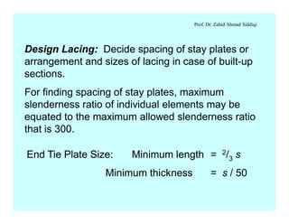
An = Ag - n(d + 3)tf
= 2 ´ [2610 - 2 (20 + 3) ´ 9.9]
= 4309.2 mm2
ftTn = lesser of
1. ft Fy Ag / 1000
= 0.90´250´2´2610 / 1000 = 1174.5 kN
2. ft Fu U An / 1000
= 0.75´400´0.80´4309.2/1000 = 1034.2 kN
= 1034.2 kN
16. Prof. Dr. Zahid Ahmad Siddiqi
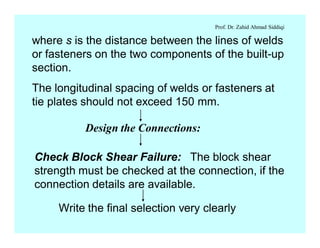
Iy about individual centroid = 63.7 ´ 104 mm4,
x = 14 mm
Iy (built-up) = [63.7 ´ 104 + 2610 (50 + 14)2] ´ 2
= 2265.5 ´ 104 mm4
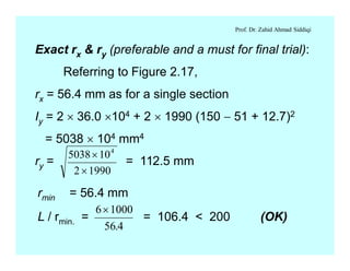
rmin = ry = 65.88 mm
L / r = 5000 / 65.88 = 75.9 < 300 (OK)
Loading cycles are assumed to be less than
20,000 and hence no reduction in strength due to
fatigue is considered.
The factored tensile capacity is 1034.2 kN
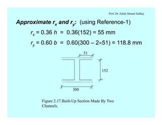
ry =
26102
105.2265 4
´
´
= 65.8 mm
17. Prof. Dr. Zahid Ahmad Siddiqi
Example 2.6: Select a W-section to resist a dead
tensile load of 1020 kN and a service tensile live
load of 680 kN using A36 steel and AISC LRFD
Specification. The member is to be 9m long and is
to be connected through its flanges only. Assume
that there can be as many as four 20mm rivets at
any one cross-section (two in each flange).
Fasteners per line are at least three and bf of the
W-section may be assumed to be lesser than 2/3 d
for the initial calculation of shear lag factor.
18. Prof. Dr. Zahid Ahmad Siddiqi
Solution:
TD = 1020 kN ; TL = 680 kN ; l = 9 m
Tu = 1.2 TD + 1.6 TL = 2312 kN
Areq = larger of
= 10,276 mm2
and
2509.0
10002312
9.0
1000
´
´
=
´
y
u
F
T
2
85.040075.0
10002312
75.0 ´´
´
=
´´ RUF
T
u
u
= 10,667 mm2
19. Prof. Dr. Zahid Ahmad Siddiqi
Areq = 10,667 mm2
bmin = 3.25 d + 26 = 3.25(20) + 26 @ 91 mm
(the web does not have bolts).
Approximate minimum flange width required = 91
´ 2 = 182 mm
Options for selection of section:
W200 x 86 A = 11,000 mm2
W310 x 86 A = 11,000 mm2
W410 x 85 A = 10,800 mm2
Weight is relatively lesser for this section but the
depth is excessively large.
20. Prof. Dr. Zahid Ahmad Siddiqi
Trial section: W200 x 86
A = 11,000 mm2
bf = 209 mm
tf = 20.6 mm
rx = 92.7 mm
ry = 53.3 mm
tw = 13 mm
Projected flange = 209 / 2 = 104.5 mm
> bmin (OK)
21. Prof. Dr. Zahid Ahmad Siddiqi
Capacity Check:
bf / d = 209 / 222 = 0.941 > 2/3
In the absence of the detailed connection details,
the AISC specification and the table in Reference-1
gives the efficiency factor as U = 0.9.
An = Ag – n (d + 3) tf
= 11,000 – 4(20 + 3)(20.6) = 9,105 mm2
ft Tn = 0.90 Fy Asel
= 0.9 x 250 x 11,000/1000 = 2,475 kN > Tu
22. Prof. Dr. Zahid Ahmad Siddiqi
ft Tn = 0.75 Fu U An
= 0.75 x 400 x 0.9 x 9,105/1000
= 2,458 kN > Tu (OK)
rmin = smaller of rx and ry = 53.3 mm
l / rmin = = 168.8 < 300 (OK)
3.53
10009´
Loading cycles are assumed lesser than 20,000, if
not given.
Design connections. Block shear cannot be
checked until the connection design is available.
Final Selection: W200 x 86
23. Prof. Dr. Zahid Ahmad Siddiqi
GENERAL CONSIDERATIONS FOR
SELECTION OF SECTIONS
The type of connections used for the structure often
affects the choice of member type.
It is very difficult to apply bolts/rivets between some
steel sections and the required gusset plates, while
the same sections may easily be welded to the
gusset plates.
For example, plate-members are to be welded to
other members in most the cases when the two
plates are lying perpendicular to each other.
24. Prof. Dr. Zahid Ahmad Siddiqi
The designer should select members such that
connections to other members in the structure are
easy.
More parts of the section as far as possible are
connected at the end to improve joint efficiency and
to obtain a compact arrangement.
Most commonly, W-sections have gusset plates on
both sides of the section connected with the flanges.
Filler plates are to be used if depths of the joining
sections are different.
Gusset plates present within the two angles connect
double angles.
25. Prof. Dr. Zahid Ahmad Siddiqi
Sometimes zero-force members are required for
internal stability of frame, for minor loads like fans,
false ceiling, etc., for future changes in loading,
and for temperature effects.
These may also the used to reduce effective
lengths of other members.
Section is selected for these members keeping in
view the following:
26. Prof. Dr. Zahid Ahmad Siddiqi
1. Preferably slenderness ratio equal to limiting
maximum value for compression members is
maintained, which is equal to 200.
Using this criterion if the size becomes
excessive, slenderness ratio of tension
members may be provided.
However, if still the section is excessively
bigger, a section comparable with other truss
members may be used.
2. Connected legs should have a preferable
width greater than or equal to the minimum
width required for proper connection.
27. Prof. Dr. Zahid Ahmad Siddiqi
3. If the zero force member is a top or bottom
chord member, continue the same section as
present in the adjoining panel.
MEMBERS UNDER STRESS REVERSAL
The maximum factored tensile and compressive
forces acting at different time instants due to
different load combinations may be represented by
the following notation:
Tu = magnitude of ultimate tensile factored force.
Pu = magnitude of factored compressive force.
28. Prof. Dr. Zahid Ahmad Siddiqi
There are three possibilities of design based on the
relative magnitudes of Tu and Pu, as explained in
the following cases:
Case 1. Tu < Pu and Welded Connections
OR Tu < 0.75Pu
and Riveted / Bolted Connections
Neglect the tensile force and design the member
as pure compression member.
29. Prof. Dr. Zahid Ahmad Siddiqi
Case 3. Tu > (1 + 0.015 L2) Pu
where L = length of member in meters.
Case 2. Pu > 10% of Tu
and (KL/r)max = 300
The compressive force may be ignored and the
member is designed as a pure tension member.
30. Prof. Dr. Zahid Ahmad Siddiqi
The member may be designed for a tension of Tu.
However, during the capacity check, it is made sure
that the compression capacity fcPn is greater than
or equal to Pu.
It is better to keep the slenderness ratio up to 200
for these members.
Case 4. If the conditions of Case-1 and Case-2
are not satisfied, the section is to be designed for Pu
as a compression member.
It is checked later that ftTn is greater than or equal to
Tu.
31. Prof. Dr. Zahid Ahmad Siddiqi
Note: The factored force may be replaced with the
service force in case of allowable stress design.
Example 2.7: Design the member of a roof truss
using LRFD procedure carrying a factored
compressive force of 450 kN and a factored tensile
force of 840 kN; l = 6m. Built-up section consisting
of two channels back to back with a total width of
300 mm is to be used. Check the member under
stress reversal. Welded connections are to be
used.
32. Prof. Dr. Zahid Ahmad Siddiqi
Solution:
Pu = 450 kN
Tu = 840 kN
(1 + 0.015 L2) Pu = (1.54) (450) = 693 kN
Tu > (1 + 0.015 L2) Pu
Design first as a tension member and then
check for Pu (Case 2).
33. Prof. Dr. Zahid Ahmad Siddiqi
For welded connections,
Areq = = 3733 mm2
2509.0
1000840
9.0
1000
´
´
=
´
y
u
F
T
Areq for one channel = = 1867 mm2
bmin = 50 mm for welded connections
3733
2
Options available: 1. C 150 ´ 15.6
2. MC 310 ´ 15.8
Trial section: 2Cs 150 ´ 15.6 (Figure 2.16)
A = 1990 mm2
34. Prof. Dr. Zahid Ahmad Siddiqi
d = 152mm ; bf = 51mm
Ix = 633 ´ 104 mm4
Iy = 36.0 ´ 104 mm4
x = 12.7 mm
rx = 56.4 mm ; ry = 13.4 mm
x
c.g
.
Figure 2.16.Location of Centroid
For A Channel Section.
35. Prof. Dr. Zahid Ahmad Siddiqi
Capacity Check:
ftTn = 0.9 Fy Asel
= 0.9 ´ 250 ´ (2 ´ 1990) / 1000
= 895.5 kN > Tu (OK)
ftTn = 0.75 Fu U An
= 0.75 ´ 400 ´ 1.0 ´ (2´1990)/1000
= 1194 kN > Tu (OK)
36. Prof. Dr. Zahid Ahmad Siddiqi
Approximate rx and ry: (using Reference-1)
rx = 0.36 h = 0.36(152) = 55 mm
ry = 0.60 b = 0.60(300 – 2´51) = 118.8 mm
152
300
51
Figure 2.17.Built-Up Section Made By Two
Channels.
37. Prof. Dr. Zahid Ahmad Siddiqi
Exact rx & ry (preferable and a must for final trial):
Referring to Figure 2.17,
rx = 56.4 mm as for a single section
Iy = 2 ´ 36.0 ´104 + 2 ´ 1990 (150 - 51 + 12.7)2
= 5038 ´ 104 mm4
ry = = 112.5 mm
5038 10
2 1990
4
´
´
rmin = 56.4 mm
L / rmin. = = 106.4 < 200 (OK)
6 1000
56 4
´
.
38. Prof. Dr. Zahid Ahmad Siddiqi
Design of Lacing:
Check For Compressive Strength:
These parts will be completed after doing
the next chapter.
Loading cycles are assumed less than 20,000
Design Connections
39. Prof. Dr. Zahid Ahmad Siddiqi
ASSIGNMENT FOR TENSION MEMBER DESIGN