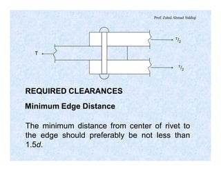
This document discusses lap joints, bolted connections, and riveted connections. It provides details on:
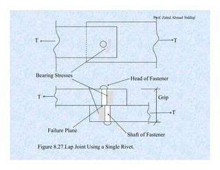
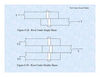
- The components and stresses involved in a basic lap joint using a single fastener under tension or compression.
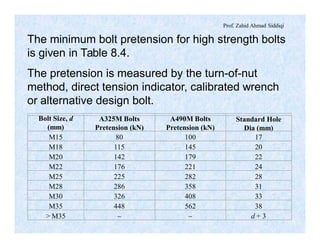
- Requirements for bolted connections including minimum pretension values for high-strength bolts and methods for measuring pretension.
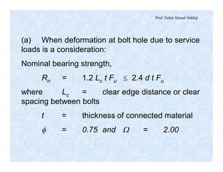
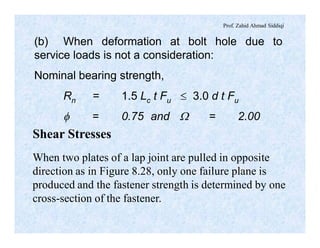
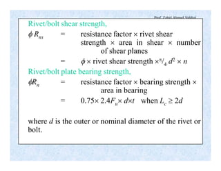
- Types of stresses fasteners experience including shear stresses at the interface of joined parts and bearing stresses transmitted into the surrounding plates.
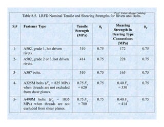
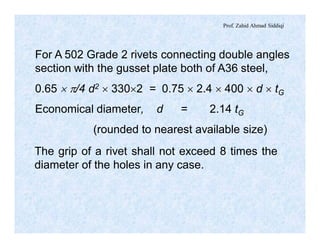
- Properties and grades of rivets commonly used in structural connections as well as their tensile and shear strengths.
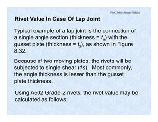
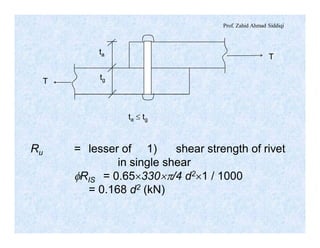
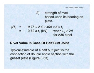
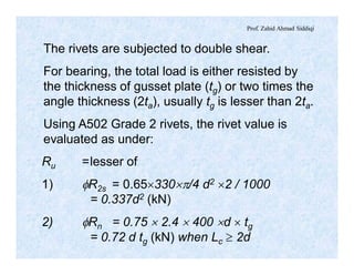
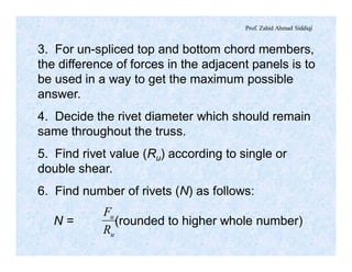
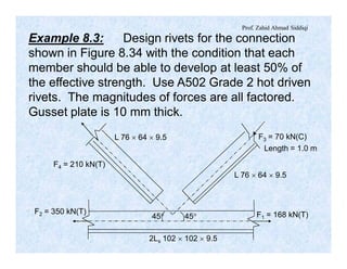
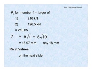
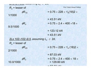
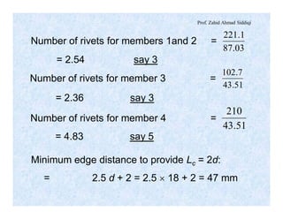
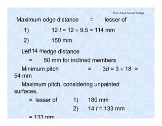
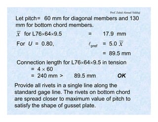
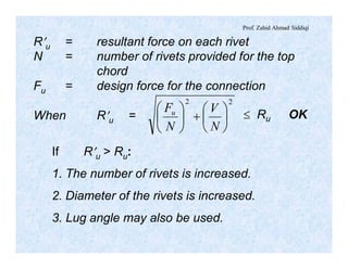
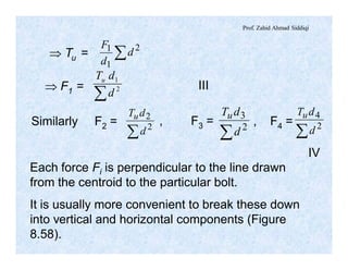
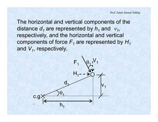
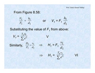
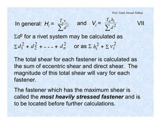
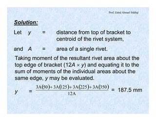
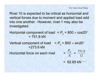
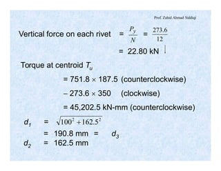
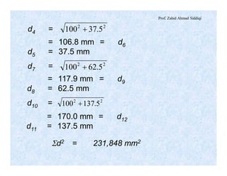
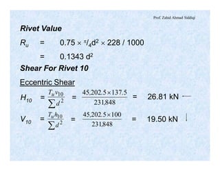
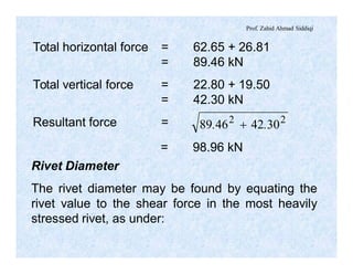
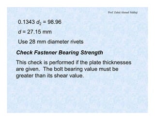
- Methods for calculating the load capacity ("rivet value") of single rivets in lap joints
The document discusses different types of beams used in structures. It defines a beam as a structural member subjected primarily to bending. Different types of beams discussed include girders, secondary beams, joists, purlins, stringers, floor beams, girts, lintels and spandrels. Beams are classified based on their position, end conditions, fabrication method, and general span ranges. The document also covers beam analysis, including the flexure formula, stability of beam sections, and classification of beam sections as compact, non-compact and slender.
Connections are critical structural elements that join members together to transfer forces safely. Connection design is more important than member design, as connection failures can cause widespread structural collapse. Rigid connections provide strength and ductility to redistribute stresses during events like earthquakes. Common connection types include welded, riveted, and bolted connections, as well as moment connections, shear connections, and splices. Moment connections are particularly important for continuity and resisting lateral loads. Proper connection design is necessary to ensure structural integrity and safety.
The document discusses various types of structural connections. It begins by defining connections as devices that join structural elements together to safely transfer forces. Connection design is more critical than member design. Failures usually occur at connections and can cause collapse.
The document then discusses different types of connections, including welded, riveted, and bolted connections. Connections are further classified based on the forces transferred, such as truss connections, fully restrained/moment connections, and partially restrained/shear connections. Specific connection types for buildings and frames like moment and shear connections are also explained. Design considerations for various structural connections like weld values, bolt values, and anchor bolts are provided.
This document discusses compression members and buckling of steel columns. It defines compression members as members subjected to compressive stresses that tend to shorten or squeeze the member. Examples given include struts, columns, truss chords, and beams. It notes that compression members are more prone to buckling than tension members. Buckling occurs when the critical buckling load is reached due to factors like member length, cross-section, end conditions, and imperfections. The effective length factor K is introduced to account for end conditions and sidesway in calculating the critical slenderness ratio.
Beam columns are structural members that experience both bending and axial stresses. They behave similarly to both beams and columns. Many steel building frames have columns that carry significant bending moments in addition to compressive loads. Bending moments in columns are produced by out-of-plumb erection, initial crookedness, eccentric loads, wind loads, and rigid beam-column connections. The interaction of axial loads and bending moments in columns must be considered through an interaction equation to ensure a safe design. Second order effects, or P-Delta effects, produce additional bending moments in columns beyond normal elastic analysis and must be accounted for through moment magnification factors.
The document discusses the objectives and process of structural design. It notes that the objectives of structural designers typically include minimizing cost, weight, construction time, and labor while maximizing efficiency. The design process involves establishing criteria, selecting a configuration, analyzing loads, evaluating member sizes through analysis and checks, redesigning if needed, designing connections, and producing design documents. Key steps are analyzing loads, selecting initial member sizes, analyzing the structure, checking requirements, and revising as needed to achieve an optimum design.
A plate girder is a beam composed of welded or riveted steel plates. It consists of two flanges and a web plate. The flanges resist bending moments while the web resists shear forces. Plate girders are commonly used for longer spans than ordinary beams, with spans ranging from 14-40 meters for railroads and 24-46 meters for highways. They have a high depth to thickness ratio for the web, making it slender. Stiffeners are added to the web to prevent buckling. Plate girders are an economical choice for longer spans where their design can be optimized for requirements.
The document discusses the design of compression members in planar trusses. It provides modifications to the slenderness ratio that must be applied when designing single angle compression members to account for potential torsional buckling. It then outlines a design flow chart for selecting compression member sections, including calculating required member capacity and area, selecting a trial section, and performing various checks related to stability, slenderness ratio and member capacity. An alternate method for selecting W-sections or double angle sections using column selection tables is also described.
The document discusses the design procedure for selecting structural steel members according to the Load and Resistance Factor Design (LRFD) method. It provides examples of calculating the load capacity of angle sections, double channel sections, and W-sections. General considerations for selecting sections are also outlined, such as compatibility with connections, minimizing weight, and checking slenderness ratios. Members that experience stress reversal are discussed, outlining three cases to determine whether to consider tensile or compressive forces in design.
This document provides information on designing tension members. It discusses typical tension members like truss members subjected to tension. Built-up sections may be required when a single shape cannot provide sufficient strength or rigidity. The gross and net areas of cross-sections are defined, with the net area accounting for holes from fasteners. Joint efficiency and the shear lag factor are discussed, which account for stress concentrations and reduce the effective net area. Fastener spacing parameters like pitch, gage, and stagger are defined. The calculation of net area accounts for reductions from holes and additions from inclined planes. Welded connections use the gross area for strength calculations. An example problem demonstrates calculating the minimum net area of a plate.
This document provides an overview of wind load calculation procedures according to the International Building Code (IBC) 2012 and American Society of Civil Engineers (ASCE) 7-10 standards. It defines important terms related to wind loads and explains changes made in ASCE 7-10 from the previous ASCE 7-05 standard. The major wind load calculation procedures covered are the directional procedure for buildings of all heights, the envelop procedure for low-rise buildings, and the wind tunnel procedure. Steps of the directional procedure are outlined, including determining the risk category, basic wind speed, wind parameters, velocity pressure coefficients, and velocity pressure.
This document discusses the design of reinforced concrete deep beams. It defines deep beams as having a span/depth ratio less than 2 or a continuous beam ratio less than 2.5. Deep beams behave differently than elementary beam theory due to non-linear stress distributions. Their behavior depends on loading type and cracking typically occurs between one-third to one-half of the ultimate load. Design considerations include checking for minimum thickness, flexural design, shear design, and anchorage of tension reinforcement.
This document discusses the properties and analysis of trusses. It defines a truss as a frame structure where all members experience axial forces. Trusses are analyzed as pin-jointed frames if the joints intersect at a single point and loads are only applied at panel points. The document compares trusses to rigid frames and outlines various truss types including common roof trusses like the Howe, Pratt, Fink and Warren trusses. It also defines related terms like pitch, rise, purlins and loads on truss roofs.
Ch8 Truss Bridges (Steel Bridges تصميم الكباري المعدنية & Prof. Dr. Metwally ...Hossam Shafiq II
This chapter discusses truss bridges. It begins by defining a truss as a triangulated assembly of straight members that can be used to replace girders. The main advantages of truss bridges are that primary member forces are axial loads and the open web system allows for greater depth.
The chapter then describes the typical components of a through truss bridge and the most common truss forms including Pratt, Warren, curved chord, subdivided, and K-trusses. Design considerations like truss depth, economic spans, cross section shapes, and wind bracing are covered. The chapter concludes with sections on determining member forces, design principles, and specific design procedures.
21-Design of Simple Shear Connections (Steel Structural Design & Prof. Shehab...Hossam Shafiq II
1. The document describes the design of a simple shear connection between a beam and column using bolts. It provides equations to check the shear strength of the bolts and bearing strength of the plate.
2. An example is presented to determine the number and size of bolts needed to resist an ultimate shear force of 1000 kN between two beams. It is determined that 7 bolts with 18 mm diameter and 98.5 mm spacing will suffice.
3. The document also checks the strength of double angles used in the connection to transfer the force and confirms the chosen angles are adequate.
The document discusses bolted connections and provides specifications for bolt hole sizes, pitch, and spacing in bolted connections according to IS 800-2007. It covers various types of bolted joints including lap joints, butt joints, and their modes of failure. High strength friction grip bolts are described which provide rigid connections through clamping action and prevent slippage. The advantages of HSFG bolts include their ability to transmit load through friction eliminating stress concentrations in holes, while their drawbacks include higher cost and fabrication efforts compared to normal bolts.
The document summarizes the design of a steel exhibition building with a circular plan. It describes the architectural features of the building including the dimensions of the exhibition hall and stalls. It then discusses the structural analysis conducted using STAAD Pro software and consideration of various loads. Next, it details the design of key structural elements like curved beams, trusses, bracings, columns, and base plates. Design calculations are provided for the curved beams. Finally, it provides a bill of materials and concluding remarks on the benefits of the tubular structural design.
Ch3 Design Considerations (Steel Bridges تصميم الكباري المعدنية & Prof. Dr. M...Hossam Shafiq II
This chapter discusses design considerations for steel bridges. It outlines two main design philosophies: working stress design and limit states design. The chapter then focuses on the working stress design method, which is based on the Egyptian Code of Practice for Steel Constructions and Bridges. It provides allowable stress values for various steel grades and loading conditions, including stresses due to axial, shear, bending, compression and tension loads. Design of sections is classified based on compact and slender criteria. The chapter also addresses stresses from repeated, erection and secondary loads.
The Manual explains the concept of transferring the load from the super structure up to the soil throughout Piles, which has a capacity of (End bearing, and Skin friction). It illustrates the steps needed to produce a full and safe foundation for your Super Structure.
23-Design of Column Base Plates (Steel Structural Design & Prof. Shehab Mourad)Hossam Shafiq II
This document discusses the design of column base plates to resist both axial loads and bending moments. It provides equations to calculate stresses on the base plate and footing. It then gives an example of designing a base plate for a column supporting an axial load of 1735 kN and bending moment of 200 kN.m. The design process involves calculating eccentricity, base plate dimensions, stresses on the footing, required plate thickness, and checking bending in two directions. The example concludes by specifying a base plate of dimensions 750mm x 500mm x 40mm that satisfies all design requirements.
This document is a course material document on structures II that covers:
- Column analysis including failure modes, end conditions, and analysis of wood and steel columns
- Column design including design of wood and steel columns using various equations and methods
- It provides examples of analyzing and designing columns and references resources on copyright and terms of use.
Doubly reinforced beams have both tension and compression reinforcement, allowing for a shallower beam depth than a singly reinforced beam. There are two cases for the behavior of doubly reinforced beams at ultimate loading:
1) Case I occurs when both tension and compression steel yield. The neutral axis depth can be calculated and the moment capacities from compression steel, concrete, and tension steel determined.
2) Case II occurs when only the tension steel yields, and the compression steel does not yield. The strain in the compression steel must be calculated.
The document discusses the behavior of doubly reinforced beams under ultimate loading conditions for both cases when compression steel does and does not yield. It provides equations to calculate forces, strains, and moment
This document discusses different types of rigid frame knee connections used to join beams and columns. Square knee joints are described, with and without diagonal stiffeners. Other knee types include square knees with brackets, straight haunched knees, and curved haunched knees. Straight haunched knees provide reasonable stiffness and rotation capacity at a lower cost than other options. The document provides design procedures and an example problem for sizing the components of a square knee connection between a W690×140 beam and W360×110 column.
This document provides guidelines for using the structural analysis software ETABS consistently within Atkins Dubai. It covers topics such as modelling procedures, material properties, element definition and sizing, supports, loading, load combinations, and post-analysis checks. The objective is to complement ETABS manuals and comply with codes such as UBC 97, ASCE 7, and BS codes as well as local authority requirements for Dubai projects. The procedures are based on standard practice in Dubai but can be revised based on specific project requirements.
This document discusses the properties and design of trusses and purlins. It defines key terms related to trusses like panel loads, which are concentrated loads applied at interior panel points calculated based on the roof load and area contributing to that point. Trusses are analyzed considering unit gravity and wind loads, and the principle of superposition is used. The document provides guidelines for designing purlins, including calculating loads, selecting trial sections, checking stresses and dimensions, and designing sag rods if needed. An example is given to demonstrate the purlin design process for given roof load and truss geometry data.
This document discusses various aspects of weld design and specifications according to Indian codes. It covers topics like maximum and minimum size of fillet welds, effective length calculations, design of fillet and groove welds under different loading conditions, intermittent welds, balancing welds in tension members, welded connections like beam to column, bracket connections, tubular joints and splices. The document also discusses failure of moment connections during earthquakes and prequalified seismic moment connections according to American codes.
This document discusses tension members and how to calculate their net cross-sectional area. Tension members experience axial tensile forces that cause elongation. Built-up members may be needed if a single shape lacks sufficient capacity, rigidity, or requires unusual connection details. Net area calculation accounts for holes from fasteners by subtracting their total area from the gross area. Inclined portions of the failure plane add area. Shear lag reduces the effective net area based on connection efficiency. Pitch, gage, and stagger refer to fastener spacing.
The document discusses sliding contact bearings and hydrodynamic journal bearings. It provides classifications of bearings based on the nature of contact, advantages and disadvantages of sliding contact bearings over rolling contact bearings. It describes hydrodynamic and hydrostatic bearings. The document also includes examples of design calculations for hydrodynamic journal bearings, including determining minimum oil film thickness, coefficient of friction, power loss, oil flow rate, side leakage, and oil temperature selection.
IRJET- Comparision between Experimental and Analytical Investigation of Cold ...IRJET Journal
This document compares the experimental and analytical investigation of the structural behavior of cold formed steel angle sections under tension loading. 108 specimens of different cold formed steel angle sections with varying thicknesses were tested experimentally. The ultimate loads from the experiments were then compared to the predicted loads from several international design codes - Australian/New Zealand standard AS/NZS 4600-2005, American Iron and Steel Institute AISI Manual from 2001, and British Standard BS 5950-1998 Part 5. In general, the codes provided conservative predictions of the ultimate loads compared to the experimental values. Tables 1 and 2 show examples of the comparison between experimental and predicted ultimate loads for various angle section specimens.
This document discusses different types of couplings used to join rotating shafts, including rigid couplings, flexible couplings, and muff couplings. It provides details on the construction and working of bush-pin flexible couplings and clamp couplings. Bush-pin flexible couplings can tolerate some misalignment of the shafts and absorb vibrations. Their design involves calculating the diameter of pins and bushes based on the torque transmitted and permissible stress values. Clamp couplings are easier to assemble and disassemble compared to rigid muff couplings, but are more difficult to balance at high speeds and unsuitable for shock loads.
1) The document describes the design procedure for a bushed-pin flexible coupling. It begins by explaining the need for flexible couplings to accommodate misalignment between connected shafts.
2) The key steps in the design procedure are: (1) Calculate the shaft diameter based on power and torque equations, (2) Determine flange dimensions using empirical relations of the shaft diameter, (3) Calculate pin diameter based on number of pins and shaft diameter, (4) Find rubber bush dimensions using torque and pitch circle diameter equations, (5) Select a standard key size and check stresses.
3) The main advantage of this flexible coupling is that it can accommodate misalignment between shafts, while the larger pin diameter
Tension members are structural elements subjected to direct tensile loads. Their strength depends on factors like length of connection, size and spacing of fasteners, cross-sectional area, fabrication type, connection eccentricity, and shear lag. Failure can occur through gross section yielding, net section rupture, or block shear. Design involves selecting a member with sufficient gross area to resist factored loads in yielding, then checking strength considering net section rupture and block shear failure modes.
Comparative study of Structural Analysis of a Multi-plate ClutchIRJET Journal
This document presents a comparative study of the structural analysis of a multi-plate clutch using two different friction lining materials: titanium carbide (Ti-C) and carbon fiber. A 3D model of the multi-plate clutch was created in Solidworks and analyzed in Ansys Workbench to compare stress, strain, deformation, and other metrics between the two materials. The results showed that under dynamic loading conditions, the carbon fiber material exhibited less total deformation and maximum elastic strain than the titanium carbide material. Therefore, clutch plates using carbon fiber as the friction material would operate better than those using titanium carbide when transmitting the same amount of torque.
Lecture Riveted Joints by molvie imran.pptxBDULQAYYUM
This document provides an overview of rivets and riveted joints. It discusses the types of rivets used in construction, their materials, and essential properties. It describes the methods of riveting and classifications of rivet heads and riveted joints. Key terminology used in riveted joints is defined. The document also discusses caulking and fullering operations, common failure modes of riveted joints, and equations to determine the strength of riveted joints. The overall purpose is to introduce the topic of rivets and riveted joints for mechanical engineering applications.
This document discusses the design of compression members. It defines compression members as members subjected to compressive loads that tend to shorten or squeeze them. Common examples include columns, struts, and members with bending and compressive loads. The strength of compression members is reduced compared to tension members due to their tendency to buckle when loaded. Longer columns have a greater risk of buckling. Other factors like load eccentricity, imperfections, and residual stresses also influence the buckling load. The document discusses various structural sections used for columns and considerations for local and overall buckling stability.
07-Strength of Bolted Connections (Steel Structural Design & Prof. Shehab Mou...Hossam Shafiq II
1. The document discusses different types and grades of bolts used in structural connections including A307, A325, and A490 bolts. It provides nominal tensile and shear strengths for each grade.
2. Bolted connections are classified based on the tightening method as snug-tight, pretensioned, or slip-critical. Pretensioned and slip-critical connections are used for load reversal or combined shear and tension loading.
3. Common methods to fully tension high-strength bolts include the turn-of-nut method, calibrated wrench method, and direct tension indicators.
The document provides an example calculation to determine the factor resistance of a bolted connection considering slip-critical
The document discusses the benefits of exercise for mental health. Regular physical activity can help reduce anxiety and depression and improve mood and cognitive functioning. Exercise causes chemical changes in the brain that may help protect against mental illness and improve symptoms.
Design aids for tension members as per revised is 800 2007eSAT Journals
Abstract The B.I.S. recently revised the new IS: 800-2007 . This is based on limit state method. This new code includes variety in elements like tension members, compression members , flexural members, combined connection, combined axial and bending design of members. The B.I.S. has yet not published any design aids based on new IS: 800-2007. For saving time in various design of structural steel section, one need to have their own computer programme or design aids or spreadsheet which is based on IS: 800-2007. In this research we have developed excel programme spreadsheet to analyze & design tension members, which will help the structural designer to save their time in designs. Also we have prepared design aids to find out the capacity on angled tension member with single row of bolts connected to the gusset plate. Keywords: Tension members, Design aids , IS:800-2007 , Analysis , Designing , Spreadsheet, Structural steel
The document discusses different types of welded joints used in mechanical assemblies, including butt joints, fillet/lap joints, transverse fillet welds, and parallel fillet welds. It provides formulas to calculate the strength of different welded joint configurations based on factors like weld throat area, plate dimensions, and allowable tensile and shear stresses. Examples are given to demonstrate calculating the required weld lengths for specific plate joining problems based on the given stresses and loads.
This document contains a summary of 5 lectures on the design of riveted and welded joints:
1. Lecture 1 introduces riveted joints, including types of rivets, types of riveted joints, and riveting methods.
2. Lecture 2 describes types of riveted joints in more detail, including lap joints and butt joints.
3. Lecture 3 covers failures of riveted joints, riveting processes like caulking and fullering, and the design of longitudinal butt joints for boilers.
4. Lectures 4 and 5 provide more details on the design of longitudinal and circumferential lap joints for boilers, including determining thickness
IRJET- Analysis of Hot Rolled Steel Angles Under TensionIRJET Journal
This document analyzes the block shear capacity and failure mechanisms of hot rolled steel angles used as tension members. It discusses the design strengths according to yielding of the gross section, rupture of the critical section, and block shear. Block shear is a failure that combines tensile rupture on one plane and shear yield or rupture on a perpendicular plane. The document outlines the methodology used to test steel angle specimens in a Universal Testing Machine and compares the results to design equations in the Indian code IS 800:2007. It was found that the limit state method provides more accurate design strengths and is more economical than other methods. Testing confirmed that locally available steel angles meet code criteria.
1) The document discusses the design of laterally supported flexural steel members. It covers topics like conditions for beams to qualify as laterally supported, modes of failure for beams, and design procedures.
2) An example problem is presented showing the design of a simply supported laterally supported beam carrying a factored point load at midspan. The design is carried out selecting an appropriate I-section, checking shear and bending capacity, and verifying against web buckling and crippling.
3) Key steps in the design of laterally supported beams are outlined, including determining loads, selecting section, classification, checking shear and bending strength, and verifying local failures like web buckling and crippling are
Shear Strenth Of Reinforced Concrete Beams Per ACI-318-02Engr Kamran Khan
This document provides a 4 PDH course on the shear strength of reinforced concrete beams per ACI 318-02. It covers topics such as the different modes of failure for beams without shear reinforcement, the shear strength criteria, and calculations for the shear strength provided by concrete. The course content includes introductions to shear stresses in beams, Mohr's circle analysis, beam classifications, and equations for determining nominal shear strength based on the concrete strength and web reinforcement.
This document summarizes riveted joints, including their applications, components, types, and failure modes. Riveted joints are used to connect parts in pressure vessels, bridges, ships, airplanes, cranes, and buildings. A rivet consists of a head and shank. When forming a joint, rivets are inserted through holes in plates and the protruding end is hammered to form a second head. Common rivet materials include steel, nickel steel, brass, and aluminum. Key types of riveted joints are lap joints and butt joints. Failure can occur via bending of rivets or plates, shearing of rivets, crushing of rivets or plates, or rupture of
Vertical alignment of highway (transportation engineering)Civil Zone
Vertical curves are used in highway design to gradually transition between two different slopes or grades. There are two main types - crest vertical curves, which are used on roadway tops, and sag vertical curves, which are used on dips. The minimum length of a vertical curve is determined based on providing the required stopping sight distance for a given design speed. Additional criteria like passenger comfort, drainage, and appearance may also influence the curve length selected. Longer vertical curves generally provide a smoother ride but require more construction costs.
Traffic studies (transportation engineering)Civil Zone
Traffic studies analyze traffic characteristics to inform transportation design and control. Key studies include traffic volume, speed, origin-destination, and accident analyses. Traffic volume studies count vehicles over time and are used for planning, operations, and structural design. Speed studies measure spot, average, running, and journey speeds to understand traffic patterns and inform control and design. Origin-destination studies identify the origins and destinations of trips to understand land use and travel patterns. Together these studies provide essential traffic data for transportation planning and management.
Level of service (los) multilane hwys 02 (transportation engineering)Civil Zone
This document discusses the analysis of level of service (LOS) on multilane highways. It provides key differences between freeways and multilane highways, such as access control and presence of traffic signals. It then outlines base conditions for LOS analysis on multilane highways, including lane width, lateral clearance, vehicle types, and terrain. The free-flow speed is calculated using factors for these conditions. Examples are provided to demonstrate calculating the free-flow speed using the base free-flow speed and adjustment factors for lane width, lateral clearance, median, and access points. Finally, it shows how to determine the volume-to-capacity ratio and establish the LOS based on density, using values from the example.
Introduction to transportation engineeringCivil Zone
Transportation engineering involves the planning, design, and management of transportation facilities to provide safe and efficient movement of people and goods. A key aspect of transportation engineering is road design. Some essential elements of a typical road cross-section include the traveled way for vehicles, shoulders for stopped vehicles and bicycles, medians to separate opposing traffic, drainage channels to remove surface water, and barriers or guardrails to prevent vehicles from leaving the roadway. Transportation engineers must consider all of these elements and their widths, slopes, and designs to develop roadways that are effective and safe for users.
Highway materials (transportation engineering)Civil Zone
This document discusses various materials used in highway construction. It describes aggregates, which are granular materials used in bases, subbases and backfill. Important properties of aggregates include particle size and hardness. Particle size distribution is determined through grain-size analysis and sieving. Hardness is measured using tests such as the Los Angeles abrasion test. Bituminous materials, commonly known as asphalt, are also discussed. Types of asphalt include asphalt cement and cutback asphalt. Specifications and tests for aggregates and asphalt are provided according to standards like AASHTO and ASTM.
Capacity & level of service (transportation engineering)Civil Zone
This document discusses highway design speed and level of service. It defines design speed as the maximum safe speed for a road based on its geometric design features. Level of service is a qualitative measure of traffic conditions on a roadway, ranging from free-flowing traffic at LOS A to congested traffic at LOS F. The document provides examples of calculating level of service for a highway based on factors like lane width, access points, and traffic volume using methods from the Highway Capacity Manual. It shows how changes to the road design, such as adding lanes or widening lanes, can improve the level of service.
Alighnment & horizontal alignment of highway (transportation engineering)Civil Zone
This document discusses the alignment of highways, including horizontal and vertical elements. It covers topics such as grade line, horizontal and vertical curves, sight distance requirements, and super elevation. The key points are:
- Highway alignment consists of horizontal and vertical elements, including tangents and curves. Curves can be simple, compound, spiral, or reverse.
- Grade line refers to the longitudinal slope/rise of the highway. Factors in selecting a grade line include earthwork, terrain, sight distance, flood levels, and groundwater.
- Horizontal alignment deals with tangents and circular curves that connect changes in direction. Vertical alignment includes highway grades and parabolic curves.
- Proper design of curves
- Hydraulics engineering is the application of fluid mechanics principles to water-related structures like canals, rivers, dams and reservoirs. It is a branch of civil engineering concerned with water flow and conveyance.
- Ancient Egyptians, Mesopotamians, and Armenians made important early contributions to hydraulics engineering, developing irrigation systems using canals and qanats.
- Notable hydraulic structures through history include one of the world's oldest dams built in Egypt between 2950-2690 BC, and ship locks that raised or lowered boats between different water levels.
This document provides an introduction to hydropower engineering. It discusses how hydropower works by capturing the kinetic energy of falling water through turbines connected to generators. The amount of electricity generated depends on water flow rate and head (drop height). It also categorizes different types of hydropower developments including run-of-river, diversion canal, storage, and pumped storage plants. Site selection factors for hydropower include available water resources, water storage capacity, water head, and accessibility of the site.
Dams and Reservoirs -Hydraulics engineeringCivil Zone
Dams are barriers built across rivers or streams to control water flow for uses like irrigation, hydropower, and flood control. The main types are embankment dams made of earth or rock and concrete dams like gravity, arch, and buttress dams. Dams provide benefits like irrigation, power, flood control, and recreation but can also negatively impact river ecosystems and require relocation of people. Engineers consider factors like geology, material availability, and hydrology to select the optimal dam type and site for a given project. Ancillary structures like spillways and outlets control water release.
Similitude and Dimensional Analysis -Hydraulics engineering Civil Zone
This document discusses similitude and dimensional analysis for model testing in hydraulic engineering. It introduces key concepts like similitude, prototype, model, geometric similarity, kinematic similarity, dynamic similarity, dimensionless numbers, and model laws. Reynolds model law is described in detail, which states that the Reynolds number must be equal between the model and prototype for problems dominated by viscous forces, such as pipe flow. An example problem demonstrates how to calculate the velocity and flow rate in a hydraulic model based on given prototype parameters and Reynolds model law.
1. The document designs bearing and end bearing stiffeners for a plate girder. For the bearing stiffener, a 200 x 15 mm stiffener plate is required on both sides under the web crippling limit state.
2. For the end bearing stiffener, a 240 x 18 mm stiffener plate is required on both sides due to the web crippling and bearing stiffener requirements at unframed ends.
3. Both designs satisfy all other limit states checked such as web local yielding, web sidesway buckling, and have sufficient weld strength.
- Plate girders require stiffeners to prevent buckling of the thin webs under compression. Bearing stiffeners are located at supports and concentrated loads, while intermediate stiffeners are spaced along the web.
- Intermediate stiffeners help develop tension field action after the web buckles, allowing the girder to resist higher shear loads through a truss-like action of the stiffened web.
- The design of intermediate stiffeners involves calculating their required spacing and size based on the web dimensions and shear capacity of the girder considering both the initial buckling strength and additional strength from tension field action.
This document discusses design considerations for steel beams, including:
1. Deflection limits for buildings, bridges, and delicate machinery are discussed, ranging from L/360 to L/2000.
2. Initial beam selection can be done by limiting the span-to-depth ratio (L/d) based on the member type to indirectly control deflections.
3. Explicit span-to-depth ratio limits are provided for various member types, such as L/d ≤ 5500/Fy for buildings and L/d ≤ 20 for bridges.
4. Formulas are provided for calculating beam deflections under different loading conditions like uniform and point loads.
This document provides a flow chart for designing built-up compression members and summarizes the design of a sample column consisting of two back-to-back channels with flat lacing. The key steps are: 1) Select a built-up section that satisfies strength and stability requirements, 2) Design flat lacing to resist shear forces using bars of appropriate size, length, and strength, 3) Satisfy design checks for lacing bar geometry and capacity. For the example, two 330x74mm channels are selected and flat lacing with 50x10mm bars 425mm long is designed to resist the shear force.
Optimizing Gradle Builds - Gradle DPE Tour Berlin 2024Sinan KOZAK
Sinan from the Delivery Hero mobile infrastructure engineering team shares a deep dive into performance acceleration with Gradle build cache optimizations. Sinan shares their journey into solving complex build-cache problems that affect Gradle builds. By understanding the challenges and solutions found in our journey, we aim to demonstrate the possibilities for faster builds. The case study reveals how overlapping outputs and cache misconfigurations led to significant increases in build times, especially as the project scaled up with numerous modules using Paparazzi tests. The journey from diagnosing to defeating cache issues offers invaluable lessons on maintaining cache integrity without sacrificing functionality.
Batteries -Introduction – Types of Batteries – discharging and charging of battery - characteristics of battery –battery rating- various tests on battery- – Primary battery: silver button cell- Secondary battery :Ni-Cd battery-modern battery: lithium ion battery-maintenance of batteries-choices of batteries for electric vehicle applications.
Fuel Cells: Introduction- importance and classification of fuel cells - description, principle, components, applications of fuel cells: H2-O2 fuel cell, alkaline fuel cell, molten carbonate fuel cell and direct methanol fuel cells.
KuberTENes Birthday Bash Guadalajara - K8sGPT first impressionsVictor Morales
K8sGPT is a tool that analyzes and diagnoses Kubernetes clusters. This presentation was used to share the requirements and dependencies to deploy K8sGPT in a local environment.
A SYSTEMATIC RISK ASSESSMENT APPROACH FOR SECURING THE SMART IRRIGATION SYSTEMSIJNSA Journal
The smart irrigation system represents an innovative approach to optimize water usage in agricultural and landscaping practices. The integration of cutting-edge technologies, including sensors, actuators, and data analysis, empowers this system to provide accurate monitoring and control of irrigation processes by leveraging real-time environmental conditions. The main objective of a smart irrigation system is to optimize water efficiency, minimize expenses, and foster the adoption of sustainable water management methods. This paper conducts a systematic risk assessment by exploring the key components/assets and their functionalities in the smart irrigation system. The crucial role of sensors in gathering data on soil moisture, weather patterns, and plant well-being is emphasized in this system. These sensors enable intelligent decision-making in irrigation scheduling and water distribution, leading to enhanced water efficiency and sustainable water management practices. Actuators enable automated control of irrigation devices, ensuring precise and targeted water delivery to plants. Additionally, the paper addresses the potential threat and vulnerabilities associated with smart irrigation systems. It discusses limitations of the system, such as power constraints and computational capabilities, and calculates the potential security risks. The paper suggests possible risk treatment methods for effective secure system operation. In conclusion, the paper emphasizes the significant benefits of implementing smart irrigation systems, including improved water conservation, increased crop yield, and reduced environmental impact. Additionally, based on the security analysis conducted, the paper recommends the implementation of countermeasures and security approaches to address vulnerabilities and ensure the integrity and reliability of the system. By incorporating these measures, smart irrigation technology can revolutionize water management practices in agriculture, promoting sustainability, resource efficiency, and safeguarding against potential security threats.
Embedded machine learning-based road conditions and driving behavior monitoringIJECEIAES
Car accident rates have increased in recent years, resulting in losses in human lives, properties, and other financial costs. An embedded machine learning-based system is developed to address this critical issue. The system can monitor road conditions, detect driving patterns, and identify aggressive driving behaviors. The system is based on neural networks trained on a comprehensive dataset of driving events, driving styles, and road conditions. The system effectively detects potential risks and helps mitigate the frequency and impact of accidents. The primary goal is to ensure the safety of drivers and vehicles. Collecting data involved gathering information on three key road events: normal street and normal drive, speed bumps, circular yellow speed bumps, and three aggressive driving actions: sudden start, sudden stop, and sudden entry. The gathered data is processed and analyzed using a machine learning system designed for limited power and memory devices. The developed system resulted in 91.9% accuracy, 93.6% precision, and 92% recall. The achieved inference time on an Arduino Nano 33 BLE Sense with a 32-bit CPU running at 64 MHz is 34 ms and requires 2.6 kB peak RAM and 139.9 kB program flash memory, making it suitable for resource-constrained embedded systems.
CHINA’S GEO-ECONOMIC OUTREACH IN CENTRAL ASIAN COUNTRIES AND FUTURE PROSPECTjpsjournal1
The rivalry between prominent international actors for dominance over Central Asia's hydrocarbon
reserves and the ancient silk trade route, along with China's diplomatic endeavours in the area, has been
referred to as the "New Great Game." This research centres on the power struggle, considering
geopolitical, geostrategic, and geoeconomic variables. Topics including trade, political hegemony, oil
politics, and conventional and nontraditional security are all explored and explained by the researcher.
Using Mackinder's Heartland, Spykman Rimland, and Hegemonic Stability theories, examines China's role
in Central Asia. This study adheres to the empirical epistemological method and has taken care of
objectivity. This study analyze primary and secondary research documents critically to elaborate role of
china’s geo economic outreach in central Asian countries and its future prospect. China is thriving in trade,
pipeline politics, and winning states, according to this study, thanks to important instruments like the
Shanghai Cooperation Organisation and the Belt and Road Economic Initiative. According to this study,
China is seeing significant success in commerce, pipeline politics, and gaining influence on other
governments. This success may be attributed to the effective utilisation of key tools such as the Shanghai
Cooperation Organisation and the Belt and Road Economic Initiative.
A review on techniques and modelling methodologies used for checking electrom...nooriasukmaningtyas
The proper function of the integrated circuit (IC) in an inhibiting electromagnetic environment has always been a serious concern throughout the decades of revolution in the world of electronics, from disjunct devices to today’s integrated circuit technology, where billions of transistors are combined on a single chip. The automotive industry and smart vehicles in particular, are confronting design issues such as being prone to electromagnetic interference (EMI). Electronic control devices calculate incorrect outputs because of EMI and sensors give misleading values which can prove fatal in case of automotives. In this paper, the authors have non exhaustively tried to review research work concerned with the investigation of EMI in ICs and prediction of this EMI using various modelling methodologies and measurement setups.
Redefining brain tumor segmentation: a cutting-edge convolutional neural netw...IJECEIAES
Medical image analysis has witnessed significant advancements with deep learning techniques. In the domain of brain tumor segmentation, the ability to
precisely delineate tumor boundaries from magnetic resonance imaging (MRI)
scans holds profound implications for diagnosis. This study presents an ensemble convolutional neural network (CNN) with transfer learning, integrating
the state-of-the-art Deeplabv3+ architecture with the ResNet18 backbone. The
model is rigorously trained and evaluated, exhibiting remarkable performance
metrics, including an impressive global accuracy of 99.286%, a high-class accuracy of 82.191%, a mean intersection over union (IoU) of 79.900%, a weighted
IoU of 98.620%, and a Boundary F1 (BF) score of 83.303%. Notably, a detailed comparative analysis with existing methods showcases the superiority of
our proposed model. These findings underscore the model’s competence in precise brain tumor localization, underscoring its potential to revolutionize medical
image analysis and enhance healthcare outcomes. This research paves the way
for future exploration and optimization of advanced CNN models in medical
imaging, emphasizing addressing false positives and resource efficiency.
Presentation of IEEE Slovenia CIS (Computational Intelligence Society) Chapte...University of Maribor
Slides from talk presenting:
Aleš Zamuda: Presentation of IEEE Slovenia CIS (Computational Intelligence Society) Chapter and Networking.
Presentation at IcETRAN 2024 session:
"Inter-Society Networking Panel GRSS/MTT-S/CIS
Panel Session: Promoting Connection and Cooperation"
IEEE Slovenia GRSS
IEEE Serbia and Montenegro MTT-S
IEEE Slovenia CIS
11TH INTERNATIONAL CONFERENCE ON ELECTRICAL, ELECTRONIC AND COMPUTING ENGINEERING
3-6 June 2024, Niš, Serbia
Advanced control scheme of doubly fed induction generator for wind turbine us...IJECEIAES
This paper describes a speed control device for generating electrical energy on an electricity network based on the doubly fed induction generator (DFIG) used for wind power conversion systems. At first, a double-fed induction generator model was constructed. A control law is formulated to govern the flow of energy between the stator of a DFIG and the energy network using three types of controllers: proportional integral (PI), sliding mode controller (SMC) and second order sliding mode controller (SOSMC). Their different results in terms of power reference tracking, reaction to unexpected speed fluctuations, sensitivity to perturbations, and resilience against machine parameter alterations are compared. MATLAB/Simulink was used to conduct the simulations for the preceding study. Multiple simulations have shown very satisfying results, and the investigations demonstrate the efficacy and power-enhancing capabilities of the suggested control system.
1. Prof. Zahid Ahmad Siddiqi
Consider the example of a lap joint made by
installing a fastener and subjected to tensile or
compressive load as shown in Figure 8.27.
The fastener is placed in already drilled hole
through the parts to be joined.
The fastener has a head on one side of its shaft
for anchorage.
The other end is also worked into a head in case
of rivets and a nut is tightened at other end in
case of a bolt.
RIVETED AND BOLTED TRUSS
CONNECTIONS
2. Prof. Zahid Ahmad Siddiqi
T
T
TT
Failure Plane
Shaft of Fastener
Grip
Head of Fastener
Bearing Stresses
Figure 8.27.Lap Joint Using a Single Rivet.
3. Prof. Zahid Ahmad Siddiqi
The bolts may be arbitrarily tightened called snug
tight bolts.
Or they may be subjected to a predefined torque
producing pre-tension in the bolts and compression
on the joining plates known as high strength
bolts.
The distance between the two heads after placing
of the fasteners is called grip of the fastener.
A bolted joint in which the slip resistance of the
connection is also utilized is called Slip Critical
Joint.
4. Prof. Zahid Ahmad Siddiqi
The minimum bolt pretension for high strength bolts
is given in Table 8.4.
The pretension is measured by the turn-of-nut
method, direct tension indicator, calibrated wrench
or alternative design bolt.
Bolt Size, d
(mm)
A325M Bolts
Pretension (kN)
A490M Bolts
Pretension (kN)
Standard Hole
Dia (mm)
M15 80 100 17
M18 115 145 20
M20 142 179 22
M22 176 221 24
M25 225 282 28
M28 286 358 31
M30 326 408 33
M35 448 562 38
> M35 - - d + 3
5. Prof. Zahid Ahmad Siddiqi
The rivets used for structural purposes are driven
and installed in red hot state and are therefore
known as hot driven rivets.
Once the head is made on both sides of the rivet in
red-hot state and the rivet is then allowed to cool,
compression on the parts to be joined is produced.
This is required for close packing of members at
the joint and to avoid chattering of joints.
Further, by using hot rivets, it becomes easy to
make head by hammering.
6. Prof. Zahid Ahmad Siddiqi
ASTM Specification A502 deals with these types
of rivets and the qualities of these rivets are
defined as Grade1, Grade 2 and Grade 3 rivets.
Grade 1 rivets are having lesser strength and
their corrosion resistance is also of ordinary
level.
Grades 2 and 3 rivets are used for higher
strength and better corrosion resistance.
The tensile and shear strengths of some
common types of rivets and bolts are given in
Table 8.5.
7. Prof. Zahid Ahmad Siddiqi
Table 8.5. LRFD Nominal Tensile and Shearing Strengths for Rivets and Bolts.
S.# Fastener Type Tensile
Strength
(MPa)
ft
Shearing
Strength in
Bearing Type
Connections
(MPa)
fv
1- A502, grade 1, hot driven
rivets.
310 0.75 172 0.75
2- A502, grade 2 or 3, hot driven
rivets.
414 0.75 228 0.75
3- A307 bolts. 310 0.75 165 0.75
4- A325M bolts (Fu = 825 MPa)
when threads are not excluded
from shear planes.
0.75 Fu
= 620
0.75 0.40 Fu
= 330
0.75
5- A490M bolts (Fu = 1035
MPa) when threads are not
excluded from shear planes.
0.75 Fu
= 780
0.75 0.40 Fu
= 414
0.75
8. Prof. Zahid Ahmad Siddiqi
TYPE OF STRESSES IN FASTENERS
When the lap type connection of Figure 8.27 is
subjected to tension or compression, the fastener
is subjected to shear at a cross-section lying at the
interface of the two parts.
This cross-section at which different layers of the
fastener try to slide against each other and failure
can occur here is called a shear failure plane.
The cross-sectional area resisting shear in case of
rivets will be p/4 d2 where d is the diameter of the
rivets. However, in case of a bolt, there are two
possibilities.
9. Prof. Zahid Ahmad Siddiqi
Bolt will have more strength if failure plane lies in
unthreaded portion and less strength if failure
plane lies within the threads.
The effective area of cross-section resisting shear
in the later case will be less, considered equal to
approximately 75% of the total area without
threads, due to grooves within the threads.
However, adjustment for this reduction is made in
the strength and then area calculated on the basis
of outer diameter is used to evaluate the strength.
10. Prof. Zahid Ahmad Siddiqi
Because the fastener and plate are not fully joined
with each other, the forces from the fasteners are
transferred to the plates by bearing stresses in the
plate material surrounding the bolt on one side as
shown in Figure 8.27.
Bearing Stresses
Bearing stresses are very high but local
compressive stresses produced when two surfaces
abut each other and transfer load.
If sufficient material is available around the zone of
high bearing stresses, these stresses quickly
spread over a greater region reducing the intensity.
11. Prof. Zahid Ahmad Siddiqi
The locally stressed material is confined in nature.
For this reason and for the reason that these local
compressive stresses cannot produce fracture and
buckling, stresses up to 3.0 times the ultimate
tensile strength of plate material (3.0 Fu) may be
allowed at nominal strength level.
According to AISC, bearing strength must be
checked for both bearing type and slip critical
connections.
12. Prof. Zahid Ahmad Siddiqi
(a) When deformation at bolt hole due to service
loads is a consideration:
Nominal bearing strength,
Rn = 1.2 Lc t Fu £ 2.4 d t Fu
where Lc = clear edge distance or clear
spacing between bolts
t = thickness of connected material
f = 0.75 and W = 2.00
13. Prof. Zahid Ahmad Siddiqi
(b) When deformation at bolt hole due to
service loads is not a consideration:
Nominal bearing strength,
Rn = 1.5 Lc t Fu £ 3.0 d t Fu
f = 0.75 and W = 2.00
Shear Stresses
When two plates of a lap joint are pulled in opposite
direction as in Figure 8.28, only one failure plane is
produced and the fastener strength is determined by one
cross-section of the fastener.
14. Prof. Zahid Ahmad Siddiqi
T
T
Figure 8.28. Rivet Under Single Shear.
T
T/2
T/2
Figure 8.29. Rivet Under Double Shear.
15. Prof. Zahid Ahmad Siddiqi
This type of shear is called single shear denoted by “1s”
in calculations.
In case of the simplest half part of butt joint (Figure
8.29), three plates are trying to move relative to each
other.
Two failure planes are produced and two cross-sections
resist the applied load.
The shear strength becomes double as that of single
shear for same material and diameter of the fastener.
In other words, the applied force is divided at greater
number of cross-sections.
16. Prof. Zahid Ahmad Siddiqi
This type of shear is called double shear denoted by
“2s” in calculations.
In general, number of shear planes is always equal
to one less than the number of moving plates.
Number of shears = Number of moving plates – 1
For example, the fastener in Figure 8.30 is
subjected to 4- times shear because of five
moving plates.
It should be noted that any adjacent plates,
which cannot move in opposite direction, are
counted as a single unit in the above formula.
17. Prof. Zahid Ahmad Siddiqi
T/2
T/2
Figure 8.30. Rivet Under 4-Times Shear.
T/3
T/3
T/3
18. Prof. Zahid Ahmad Siddiqi
The four plates in Figure 8.31 are subjected to single
shear.
Figure 8.31. Single Shear In Rivet Joining Four Plates.
BEARING TYPE CONNECTIONS
When the loads to be transferred are larger than
the frictional resistance caused by tightening the
bolts, the members slip a little on each other
putting the fasteners in shear and the surrounding
member in bearing.
19. Prof. Zahid Ahmad Siddiqi
The resulting type of connections are called
bearing connections.
EFFECTIVE BEARING AREA
According to AISC, the effective bearing area of
bolts, threaded parts and rivets shall be the
diameter of such fasteners multiplied by the length
of bearing:
Rn = 2.4 Fu ´ d ´ t when Lc ³ 2d
otherwise Rn = 1.2 Fu ´ Lc ´ t
(In case deformation at service load is a
design consideration)
20. Prof. Zahid Ahmad Siddiqi
where f = 0.75 (LRFD)
and W = 2.00
t = smaller thickness of plate, subjected
to following conditions:
a) edge distance not less than 1.5 d,
b) c/c distance between fasteners not less
than 3d, and,
c) 2 or more fasteners in the line of force.
21. Prof. Zahid Ahmad Siddiqi
RIVET AND BOLT VALUE
The load in kN which a single rivet can
carry is called its rivet value (Ru).
The rivet value is smaller of rivet shear
strength and the plate bearing strength.
Ru = lesser of fRns and fRn
22. Prof. Zahid Ahmad Siddiqi
Rivet/bolt shear strength,
f Rns = resistance factor ´ rivet shear
strength ´ area in shear ´ number
of shear planes
= f ´ rivet shear strength ´p/4 d2 ´ n
Rivet/bolt plate bearing strength,
fRn = resistance factor ´ bearing strength ´
area in bearing
= 0.75´ 2.4Fu´ d´t when Lc ³ 2d
where d is the outer or nominal diameter of the rivet or
bolt.
23. Prof. Zahid Ahmad Siddiqi
Rivet Value In Case Of Lap Joint
Typical example of a lap joint is the connection of
a single angle section (thickness = ta) with the
gusset plate (thickness = tg), as shown in Figure
8.32.
Because of two moving plates, the rivets will be
subjected to single shear (1s). Most commonly,
the angle thickness is lesser than the gusset
plate thickness.
Using A502 Grade-2 rivets, the rivet value may be
calculated as follows:
24. Prof. Zahid Ahmad Siddiqi
tg
ta
ta £ tg
T
T
Ru = lesser of 1) shear strength of rivet
in single shear
fRIS = 0.65´330´p/4 d2´1 / 1000
= 0.168 d2 (kN)
25. Prof. Zahid Ahmad Siddiqi
2) strength of rivet
based upon its bearing on
plate.
fRn = 0.75 ´ 2.4 ´ 400 ´ d ´ ta
= 0.72 d ta (kN) when Lc ³ 2d
for A36 steel
Rivet Value In Case Of Half Butt Joint
Typical example of a half butt joint is the
connection of double angle section with the
gusset plate (Figure 8.33).
26. Prof. Zahid Ahmad Siddiqi
The rivets are subjected to double shear.
For bearing, the total load is either resisted by
the thickness of gusset plate (tg) or two times the
angle thickness (2ta), usually tg is lesser than 2ta.
Using A502 Grade 2 rivets, the rivet value is
evaluated as under:
Ru =lesser of
1) fR2s = 0.65´330´p/4 d2 ´2 / 1000
= 0.337d2 (kN)
2) fRn = 0.75 ´ 2.4 ´ 400 ´d ´ tg
= 0.72 d tg (kN) when Lc ³ 2d
27. Prof. Zahid Ahmad Siddiqi
T/2
T/2
T
REQUIRED CLEARANCES
Minimum Edge Distance
The minimum distance from center of rivet to
the edge should preferably be not less than
1.5d.
28. Prof. Zahid Ahmad Siddiqi
If this distance is not maintained, detailed
formulas given in the chapter on tension
members and in another article in this chapter
are to be satisfied.
The distance should be kept equal to 2.5d + 2
(mm) to obtain bearing strength equal to 2.4 Fu.
Minimum Spacing Of Fasteners
The minimum longitudinal and transverse
spacing of fasteners (pitch or gage) shall
preferably be not less than 3d.
29. Prof. Zahid Ahmad Siddiqi
This is to avoid stress concentrations and to
make drilling of holes and tightening of bolts
easier.
For spacing lesser than 3d, formulas given earlier
for tension members must be checked.
Further, to improve bearing strength of bolts, it is
better to slightly increase this spacing to a value
of 3d+3 mm, which given clear spacing (Lc) equal
to 2d.
30. Prof. Zahid Ahmad Siddiqi
Maximum Edge Distance And Spacing
The maximum distance from the center of
fastener to the nearest edge of parts shall be
lesser of 12 t and 150 mm, where ‘t’ is the
smaller thickness of the connected parts.
The pitch of fasteners is kept lesser than the
following maximum value to prevent corrosion
of loose plates from inside of the over lap:
pmax = lesser of 305 mm and 24 t for painted
and non-corrosive steels
pmax = lesser of 180 mm and 14 t for
unpainted steels
31. Prof. Zahid Ahmad Siddiqi
where t = thickness of thinner part joined
DIAMETER OF FASTENER
Minimum diameter of rivets and bolts for trusses
and other building structures is 15 mm. The
usual size of rivets or bolts used for specific
purposes is as under:
In buildings: 15, 18, 20 mm
In bridges: 22, 25, 28 mm
In warehouses and towers: 30, 32, 35 mm
32. Prof. Zahid Ahmad Siddiqi
Preferable diameter of fastener is usually taken
by the following expression:
d = t6
rounded to the nearest available size
where t = thickness of thicker part, mm
Economical diameter of fastener means the
diameter of a rivet or bolt for which the shearing
strength is theoretically equal to bearing strength
of the parts to be joined. However, for most
practical cases, it becomes difficult to use this
diameter.
33. Prof. Zahid Ahmad Siddiqi
For A 502 Grade 2 rivets connecting double angles
section with the gusset plate both of A36 steel,
0.65 ´ p/4 d2 ´ 330´2 = 0.75 ´ 2.4 ´ 400 ´ d ´ tG
Economical diameter, d = 2.14 tG
(rounded to nearest available size)
The grip of a rivet shall not exceed 8 times the
diameter of the holes in any case.
34. Prof. Zahid Ahmad Siddiqi
ADVANTAGES OF BOLTS OVER RIVETS
1. Smaller working crews are required as
compared with riveting. The efficiency of
construction is approximately double per
person.
2. Less high strength bolts may be needed as
compared with rivets.
3. The experience required to properly install
bolts is significantly lesser than is necessary
for welded and riveted connections.
4. Less noise is produced during construction as
compared with riveting.
35. Prof. Zahid Ahmad Siddiqi
5. Cheaper equipment is used to make bolted
connections compared with welded or
riveted connections.
6. Fire in case of welding and hot material in
case of rivets is avoided.
7. Fatigue strength of fully tight high strength
bolts is greater than that of rivets.
8. Future changes are very easy with bolts.
36. Prof. Zahid Ahmad Siddiqi
ROCEDURE FOR DESIGN OF
RIVETED TRUSS CONNECTIONS
1. Find design capacity of the member, ftTn or
fcPn.
2. Compare calculated factored force in the
member with the given percentage of the
member capacity (usually not less than 50%)
and select the design force for connection as
follows:
Fu = larger of 1) factored force
2) a %age of ft Tn or fcPn
37. Prof. Zahid Ahmad Siddiqi
3. For un-spliced top and bottom chord members,
the difference of forces in the adjacent panels is to
be used in a way to get the maximum possible
answer.
4. Decide the rivet diameter which should remain
same throughout the truss.
5. Find rivet value (Ru) according to single or
double shear.
6. Find number of rivets (N) as follows:
N = (rounded to higher whole number)
u
u
R
F
38. Prof. Zahid Ahmad Siddiqi
7. For better joint efficiency and lesser stress
concentrations, a minimum of 3 rivets is preferred.
Cost of few extra rivets is much lesser than extra
cost spent on the member for lesser joint efficiency.
8. The length of joint should not be excessive. If
numbers of rivets are more than approximately
five, arrange them in more rows. However, the
connection length of a tension member (l) must be
large enough to give better joint efficiency.
For U = 0.9, lpref = 10
= distance between the centroid of element
and the interface surface.
x
x
39. Prof. Zahid Ahmad Siddiqi
9. Decide the spacing and edge distances of
rivets depending on minimum and maximum
requirements. In transverse direction, place the
rivets along standard gages.
10. Check block-tearing strength as discussed
earlier for welded connections.
11. Make a neat sketch to show the results.
12. Verify that net area and U, in case of tension
members, are greater than or equal to the values
taken during the member design.
40. Prof. Zahid Ahmad Siddiqi
Example 8.3: Design rivets for the connection
shown in Figure 8.34 with the condition that each
member should be able to develop at least 50% of
the effective strength. Use A502 Grade 2 hot driven
rivets. The magnitudes of forces are all factored.
Gusset plate is 10 mm thick.
45°45°
L 76 ´ 64 ´ 9.5
L 76 ´ 64 ´ 9.5
2Ls 102 ´ 102 ´ 9.5
F2 = 350 kN(T) F1 = 168 kN(T)
F3 = 70 kN(C)
Length = 1.0 m
F4 = 210 kN(T)
41. Prof. Zahid Ahmad Siddiqi
50% capacity of L76´64´9.5 in compression
For compression members, double angle sections
should be preferred.
However, the capacity calculated based on the
assumption of concentric loading for single angle
section will be on safer side for the connection.
zr
Kl
3.13
10001´
A = 1240 mm2
= @ 76
fcFcr = 165.66 MPa
0.5fcPn = ½ ´ 165.66 ´ 1240 / 1000 @ 102.7 kN
42. Prof. Zahid Ahmad Siddiqi
50% capacity of L76´64´9.5 in tension
The calculation may be based on the
assumption that An is equal to 85% of Ag in the
absence of accurate value of net area and the
value of U may be taken equal to 0.85.
Both of these assumptions are to be checked
after the connection design.
A = 1240 mm2
0.5ft Tn = lesser of
1. 1/2 ´ 0.9 ´ 250 ´1240/1000 = 139.5
kN
2. 1/2 ´0.75´400´0.85´0.80´1240/1000 = 126.5
kN
= 126.5 kN
43. Prof. Zahid Ahmad Siddiqi
50% Capacity of 2Ls102´102´9.5 in tension
Area of one angle = 1850 mm2
Using the same assumptions as above:
0.5ftTn = lesser of
1. ½ ´
0.9´250´2´1850/1000
= 416.3 kN
2. ½ ´
0.75´400´0.85´0.80´2´1850/1000 =
377.4 kN
= 377.4 kN
44. Prof. Zahid Ahmad Siddiqi
Fu for members 1and 2= larger of
1) (larger of F2 and its 0.5ftTn)
– F1
= 377.4 – 168 = 209.4 kN
2) 210 cos45°+ 102.7 cos45°
= 221.1 kN
= 221.1 kN
Fu for member 3 = larger of
1) 70 kN
2) 102.7 kN
= 102.7 kN
45. Prof. Zahid Ahmad Siddiqi
Fu for member 4 = larger of
1) 210 kN
2) 126.5 kN
= 210 kN
t6 106d = =
= 18.97 mm say 18 mm
Rivet Values
on the next slide
47. Prof. Zahid Ahmad Siddiqi
Number of rivets for members 1and 2 =
03.87
1.221
= 2.54 say 3
Number of rivets for member 3 =
51.43
7.102
= 2.36 say 3
Number of rivets for member 4 =
51.43
210
= 4.83 say 5
Minimum edge distance to provide Lc = 2d:
= 2.5 d + 2 = 2.5 ´ 18 + 2 = 47 mm
48. Prof. Zahid Ahmad Siddiqi
Maximum edge distance = lesser of
1) 12 t = 12 ´ 9.5 = 114 mm
2) 150 mm
= 114 mLet edge distance
= 50 mm for inclined members
Minimum pitch = 3d = 3 ´ 18 =
54 mm
Maximum pitch, considering unpainted
surfaces,
= lesser of 1) 180 mm
2) 14 t = 133 mm
= 133 mm
49. Prof. Zahid Ahmad Siddiqi
x
x
Let pitch= 60 mm for diagonal members and 130
mm for bottom chord members.
for L76´64´9.5 = 17.9 mm
For U = 0.80, lpref = 5.0
= 89.5 mm
Connection length for L76´64´9.5 in tension
= 4 ´ 60
= 240 mm > 89.5 mm OK
Provide all rivets in a single line along the
standard gage line. The rivets on bottom chord
are spread closer to maximum value of pitch to
satisfy the shape of gusset plate.
50. Prof. Zahid Ahmad Siddiqi
44 44
32 32
50
60
60
60
50
60
60
50
38
64
130 130
50
Between
50 and
114
Between
50 and
114
60
44 44
32 32
50
60
60
60
50
60
60
50
38
64
130 130
50
Between
50 and
114
Between
50 and
114
60
51. Prof. Zahid Ahmad Siddiqi
Block shear may be checked by a procedure
discussed earlier. The readers are required to
perform this check.
To verify that An ³ 0.85 Ag and U = 0.80 are left
as exercise for the readers.
DESIGN OF LOADED TRUSS JOINTS
Spliced joint is a joint where the upper or lower
chord is discontinuous and it is designed like an
ordinary joint even if load is acting on it.
The loaded joint with continuous upper or lower
chord member is called un-spliced loaded joint.
52. Prof. Zahid Ahmad Siddiqi
This is also designed as for an unloaded joint.
However, the transverse component of the load is
to be transferred through the member to the
gusset plate, and this force is not considered in
the truss analysis for the axial forces (Figure
8.36).
Transverse load component (V) acts on top chord
at the joint of Figure and is to be transferred to
gusset plate through the rivets.
Hence, resultant force on rivets R¢u is to be
calculated as follows:
53. Prof. Zahid Ahmad Siddiqi
F1
F2
V
P
F4
F5
F3
q4
q3
q
F1
F2
V
P
F4
F5
F3
q4
q3
q
54. Prof. Zahid Ahmad Siddiqi
R¢u = resultant force on each rivet
N = number of rivets provided for the top
chord
Fu = design force for the connection
When R¢u =
22
÷
ø
ö
ç
è
æ
+÷
ø
ö
ç
è
æ
N
V
N
Fu
If R¢u > Ru:
1. The number of rivets is increased.
2. Diameter of the rivets is increased.
3. Lug angle may also be used.
£ Ru OK
55. Prof. Zahid Ahmad Siddiqi
BOLTS SUBJECTED TO ECCENTRIC SHEAR
Eccentrically loaded bolt/rivet groups are
subjected to direct shears and torque as shown in
Figure 8.54.
In a truss, if the center of gravity of a member is
not in line with the center of gravity of the bolts at
its end connections, moments are produced.
Eccentricity is quite obvious in a bracket and is
also present in shear connection of beam with a
column.
56. Prof. Zahid Ahmad Siddiqi
In Figure 8.55, a typical group of four bolts is
shown with the load acting at some eccentricity,
e, from the centroid of the bolt system.
This load may be transferred to the centroid but
it will then be accompanied by a torque (T = P ´
e), as shown in Figure 8.56.
Both Figures 8.55 and 8.56 are equivalent as far
as the structural behavior is concerned.
57. Prof. Zahid Ahmad Siddiqi
a)
Bracket
b) Shear
Connection of
Beam With Column
a)
Bracket
b) Shear
Connection of
Beam With Column
58. Prof. Zahid Ahmad Siddiqi
c.g. c.g.
e P P
Figure 8.55.
Typical Group of Bolts/Rivets Subjected
to Eccentric Shear.
Figure 8.56.
Eccentric Shear On a Bolt/Rivet
Group Converted to Shear and
Torque at the Centroid.
12
3 4
Tu = P ´ eGroup of
Bolts c.g. c.g.
e P P
Figure 8.55.
Typical Group of Bolts/Rivets Subjected
to Eccentric Shear.
Figure 8.56.
Eccentric Shear On a Bolt/Rivet
Group Converted to Shear and
Torque at the Centroid.
12
3 4
Tu = P ´ eGroup of
Bolts
59. Prof. Zahid Ahmad Siddiqi
The bolts shown in Figure 8.56 are subjected to
a downward force (P / N) in each fastener called
direct shear force plus the shear force due to
the torque called eccentric shear.
The force in each fastener (Fi) due to the torque
and distance of each fastener (di) from the
centroid are shown in Figure 8.57.
60. Prof. Zahid Ahmad Siddiqi
F1
F2
F3 F4
e P
d1
d2
d3
d4
c.g
.
F1
F2
F3 F4
e P
d1
d2
d3
d4
c.g
.
61. Prof. Zahid Ahmad Siddiqi
The torque causes the plate to rotate about the
centroid of the bolt connection keeping the amount of
rotation or strain at a particular bolt being
proportional to its distance from the centroid.
These strains produce stresses and forces Fi in the
bolts. Greater is the distance of a fastener from the
centroid, more will be the force.
Further, force in each fastener will be perpendicular
to the distance vector between the centroid and that
fastener.
These eccentric forces will produce same turning
effect as that of the applied torque (clockwise or
counterclockwise).
62. Prof. Zahid Ahmad Siddiqi
1
1
d
F
2
2
d
F
3
3
d
F
4
4
d
F
Magnitude Of Eccentric Shear
From Figure 8.57,
Tu =P ´ e = F1 d1 + F2 d2 + F3 d3 + F4 d4 I
For force to be proportional to the distance, we can
write:
= = =
1
2
11
d
dF
2
2
22
d
dF
3
2
33
d
dF
4
2
44
d
dF
Equation I can be written as:
Tu = +++
= ( )2
4
2
3
2
2
2
1
1
1 dddd
d
F
+++ II
63. Prof. Zahid Ahmad Siddiqi
Þ Tu = å 2
1
1 d
d
F
Þ F1 =
å 2
1
d
dTu
III
å 2
2
d
dTu
å 2
3
d
dTu
å 2
4
d
dTu
Similarly F2 = , F3 = , F4 =
IV
Each force Fi is perpendicular to the line drawn
from the centroid to the particular bolt.
It is usually more convenient to break these down
into vertical and horizontal components (Figure
8.58).
64. Prof. Zahid Ahmad Siddiqi
The horizontal and vertical components of the
distance d1 are represented by h1 and n1,
respectively, and the horizontal and vertical
components of force F1 are represented by H1
and V1, respectively.
q1
V1
H1
h1
v1
d1
c.g
.
q1F1
q1
V1
H1
h1
v1
d1
c.g
.
q1F1
65. Prof. Zahid Ahmad Siddiqi
1
1
1
1
d
h
F
V
=
1
1
d
h
From Figure 8.58:
or V1 = F1
Substituting the value of F1 from above:
å 2
1
d
hTu
1
1
1
1
d
v
F
H
=
1
1
d
v
å 2
1
d
vTu
V1 =
Similarly, Þ H1 = F1
Þ H1 = VI
V
66. Prof. Zahid Ahmad Siddiqi
å 2
d
vT iu
å 2
d
hT iu
In general: Hi = and Vi = VII
2
1d 2
2d 2
nd 2
ih
2
in
Sd2 for a rivet system may be calculated as
S + + - - - + or as S + S
.
The total shear for each fastener is calculated as
the sum of eccentric shear and direct shear. The
magnitude of this total shear will vary for each
fastener.
The fastener which has the maximum shear is
called the most heavily stressed fastener and is
to be located before further calculations.
67. Prof. Zahid Ahmad Siddiqi
One way of locating this critical rivet is to find
resultant shear for each fastener and then finding
the maximum value.
However, this procedure may require lengthy
calculations.
A visual observation is used to reduce such extra
work.
The fasteners having the maximum distance from
the centroid (corner fasteners) are expected to be
more critical.
68. Prof. Zahid Ahmad Siddiqi
Further, out of these, whichever has both
horizontal and vertical components of direct and
eccentric shears in the same direction is expected
to be the most critical.
If there is any doubt about the condition of this
fastener by visual observation, all the competing
fasteners must by investigated by calculating the
resultant shear.
The procedure is clear in Example 8.6.
69. Prof. Zahid Ahmad Siddiqi
Required Number of Fasteners
When the eccentricity of the load on a bolt group
is less than about 60 mm, it is neglected.
For a shear force of Pu (kN) and a torque of Tu
(kN-m), the number of A502 Grade 2 rivets (N) of
15 mm diameter may be approximately
determined as under:
N =
000,1570
uu TP
+
70. Prof. Zahid Ahmad Siddiqi
Example 8.6: Find the diameter of rivets for
the bracket shown in Figure 8. 59.
P=800kN (factored force)
10050 100 250
50
75
100
125
10
7
4
1
11
8
5
2
12
6
9
3
20°
c.g.
P=800kN (factored force)
10050 100 250
50
75
100
125
10
7
4
1
11
8
5
2
12
6
9
3
20°
c.g.
71. Prof. Zahid Ahmad Siddiqi
Solution:
Let y = distance from top of bracket to
centroid of the rivet system,
and A = area of a single rivet.
Taking moment of the resultant rivet area about the
top edge of bracket (12A ´ y) and equating it to the
sum of moments of the individual areas about the
same edge, y may be evaluated.
y =
( ) ( ) ( ) ( )
A12
350A3225A3125A350A3 +++
= 187.5 mm
72. Prof. Zahid Ahmad Siddiqi
N
Px
12
8.751
Rivet 10 is expected to be critical as horizontal and
vertical forces due to moment and applied load add
into one another. However, rivet-1 may also be
investigated.
Horizontal component of load = Px = 800 ´ cos20°
= 751.8 kN
Vertical component of load = Py = 800 ´ sin20°
=273.6 kN
Horizontal force on each rivet = =
= 62.65 kN
73. Prof. Zahid Ahmad Siddiqi
N
Py
12
6.273
Vertical force on each rivet = =
Torque at centroid Tu
= 751.8 ´ 187.5 (counterclockwise)
- 273.6 ´ 350 (clockwise)
= 45,202.5 kN-mm (counterclockwise)
= 22.80 kN
d1 = 22
5.162100 +
= 190.8 mm = d3
d2 = 162.5 mm
74. Prof. Zahid Ahmad Siddiqi
22
5.37100 +
22
5.62100 +
22
5.137100 +
d4 =
= 106.8 mm = d6
d5 = 37.5 mm
d7 =
= 117.9 mm = d9
d8 = 62.5 mm
d10 =
= 170.0 mm = d12
d11 = 137.5 mm
Sd2 = 231,848 mm2
75. Prof. Zahid Ahmad Siddiqi
Rivet Value
Ru = 0.75 ´ p/4d2 ´ 228 / 1000
= 0.1343 d2
å 2
10
d
vTu
848231
5137520245
,
.., ´
å 2
10
d
hTu
848231
100520245
,
., ´
Shear For Rivet 10
Eccentric Shear
H10 = = = 26.81 kN
V10 = = = 19.50 kN
76. Prof. Zahid Ahmad Siddiqi
Total horizontal force = 62.65 + 26.81
= 89.46 kN
Total vertical force = 22.80 + 19.50
= 42.30 kN
Resultant force = 22
30424689 .. +
Rivet Diameter
The rivet diameter may be found by equating the
rivet value to the shear force in the most heavily
stressed rivet, as under:
= 98.96 kN
77. Prof. Zahid Ahmad Siddiqi
0.1343 d2 = 98.96
d = 27.15 mm
Use 28 mm diameter rivets
Check Fastener Bearing Strength
This check is performed if the plate thicknesses
are given. The bolt bearing value must be
greater than its shear value.