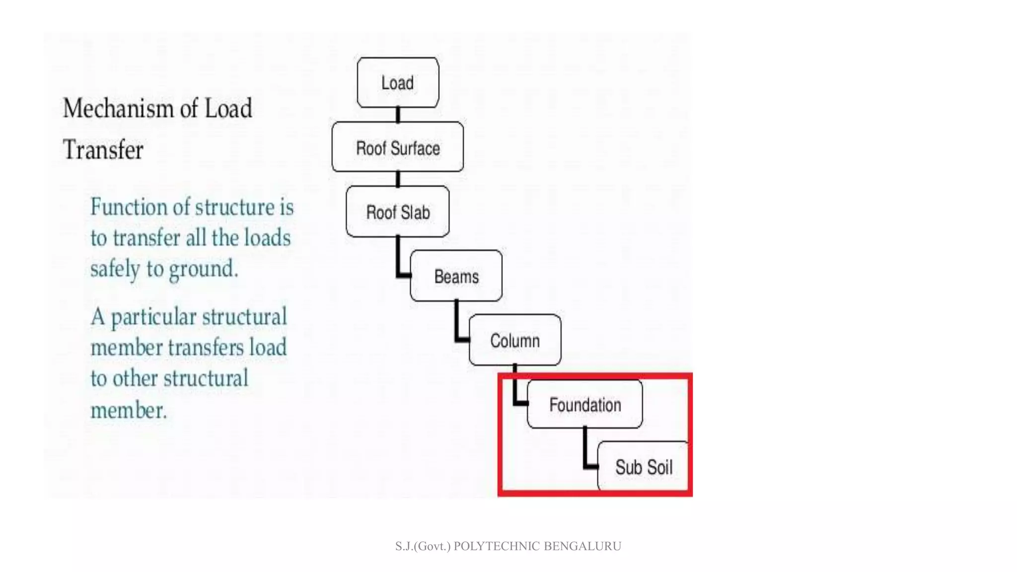
The document provides details on the design of a reinforced concrete column footing to support a column load of 1100kN from a 400mm square column. It describes the design process which includes determining the footing size, calculating bending moment, reinforcement requirements, checking shear capacity and development length. The design example shows a 3.5m x 3.5m square footing with 12mm diameter bars at 100mm c/c is adequate to support the given load based on the specified material properties and design codes. Reinforcement and footing details are also provided.


![3. Bending Moment for Design:
Consider the entire footing as
cantilever beam from the face of
The column and calculate the
BM.
Calculate span for the
cantilever portion (Hashed portion)
= plx
𝑙
2
=
𝑝𝑙2
2
Substitute l=[(B-D)/2]
Mxx= p (
𝐵−𝐷
2
)2 x
1
2
This is BM for 1m width of the beam](https://image.slidesharecdn.com/isolatedfootingdesign-191223115217/75/Isolated-footing-design-16-2048.jpg)

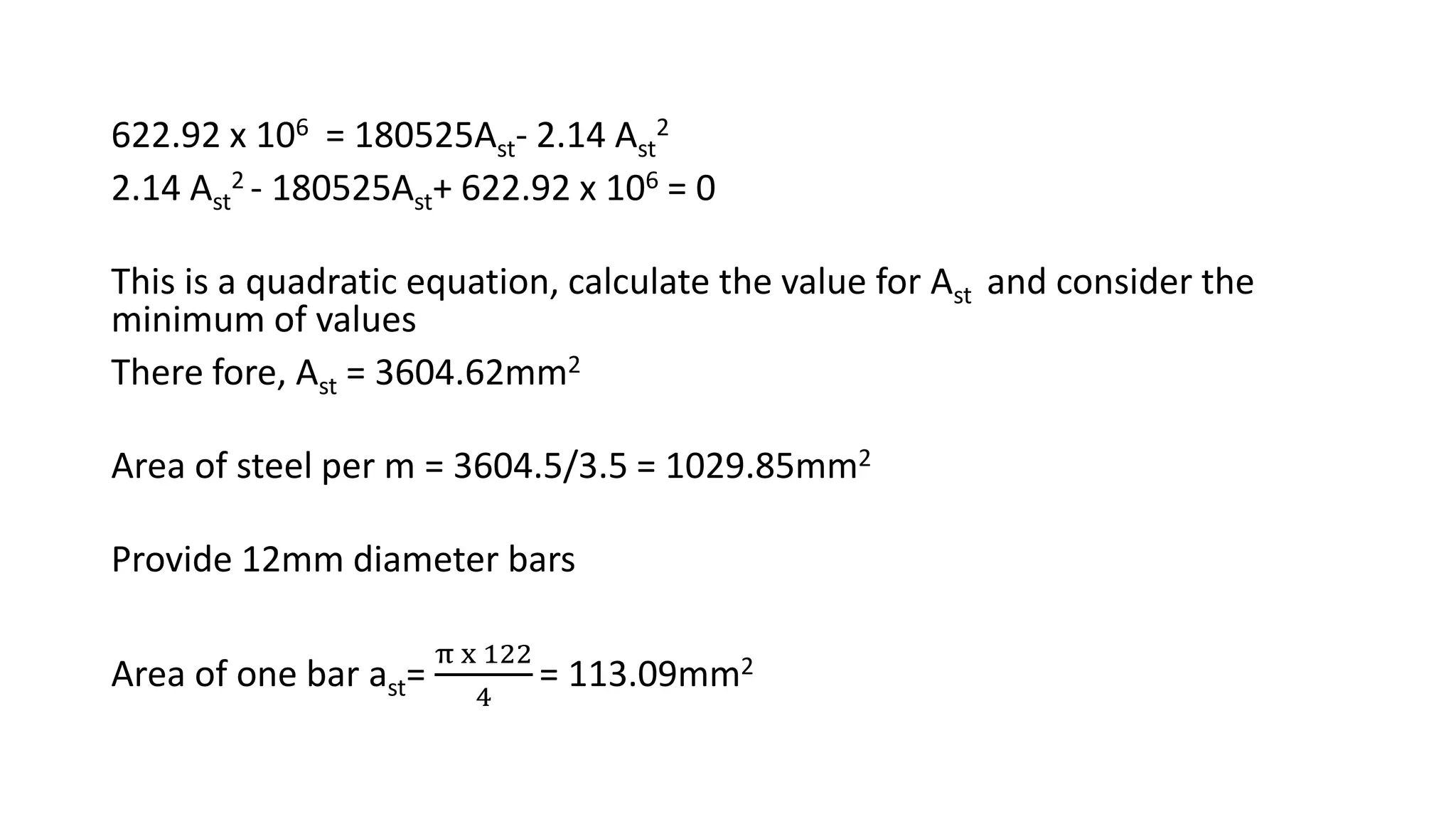
![Assume diameter bars
Area of one bar ast=
π x 𝑑𝑖𝑎2
4
= _ _ _ mm2
Spacing of reinforcement , S =
1000 ast
Ast
7) Check for one way shear :
The critical section is taken at a distance “d” away from the face of the
column y-y axis.
Shear force per m,
Vu = p x B x [(
L−D
2
)-d]](https://image.slidesharecdn.com/isolatedfootingdesign-191223115217/75/Isolated-footing-design-20-2048.jpg)
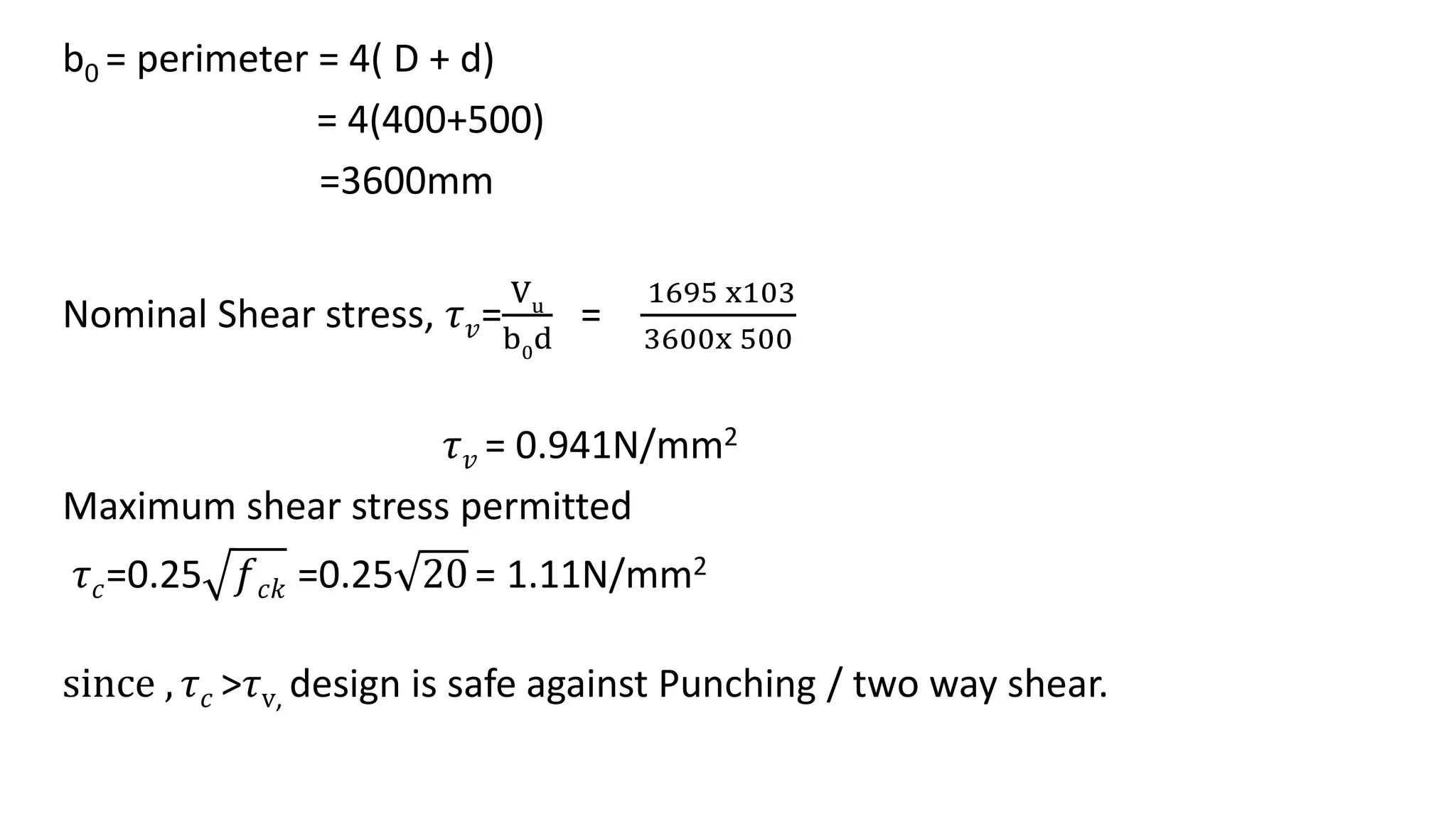
![8) Check for two way shear :
The critical section is taken at a distance
“d/2” away from the faces of the column
Shear force per m,
Vu = p x [A-(0.4+0.5)2]
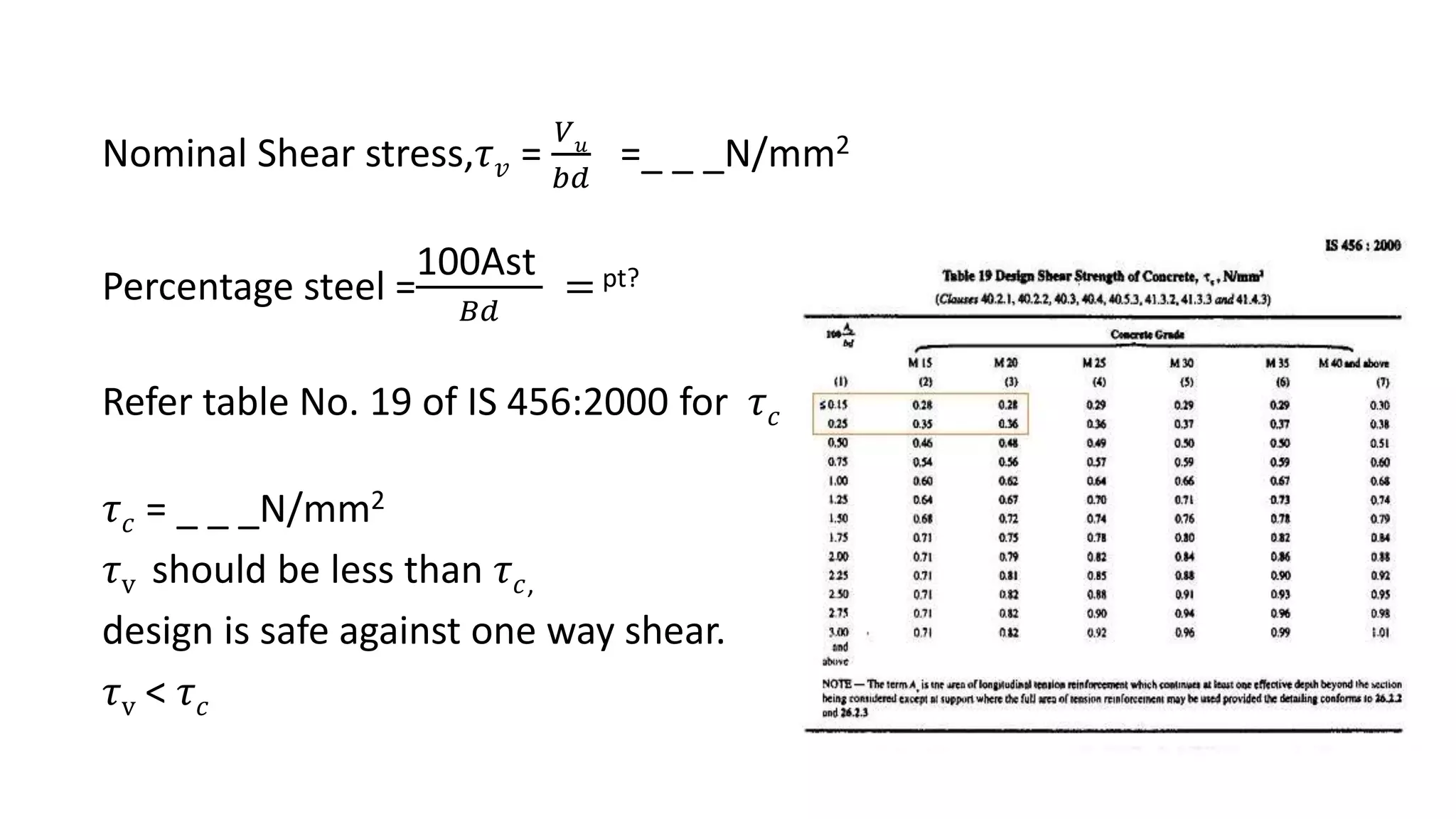
Nominal Shear stress, 𝜏 𝑣=
Vu
b0
d
b0 = perimeter = 4( D + d)
Maximum shear stress permitted
𝜏 𝑐=0.25 𝑓 𝑐𝑘
𝜏 𝑐 should be greater than 𝜏v , Then design is safe against Punching shear /
two way shear.](https://image.slidesharecdn.com/isolatedfootingdesign-191223115217/75/Isolated-footing-design-22-2048.jpg)


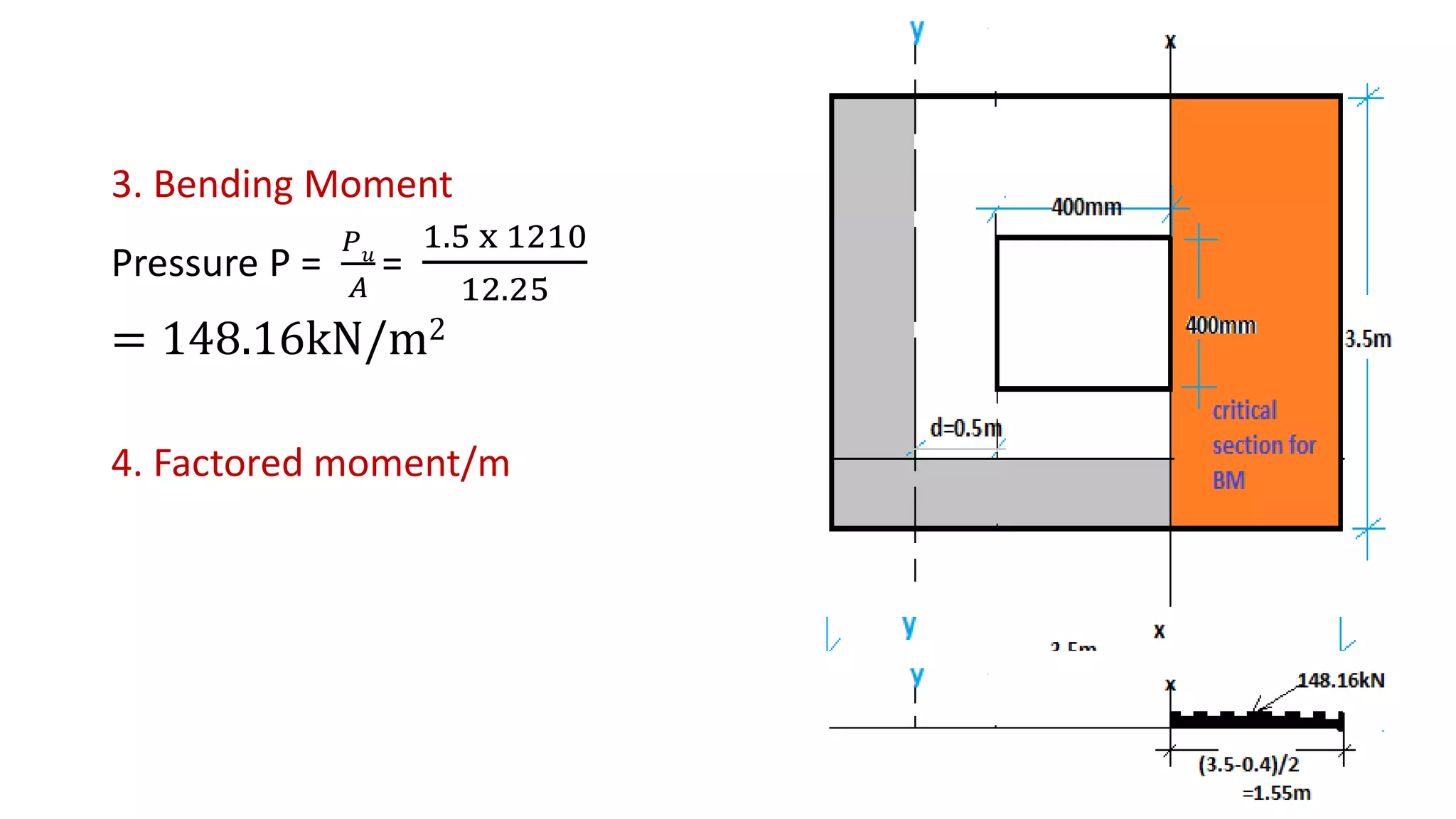
![BM about axis x-x passing through face of the
Column as shown in fig.
Mu= p x B x [
L−D
2
]2 X
1
2
= 148.16x3.5 x[
3.5−0.4
2
]2 X
1
2
= 622.92kN − m
L = B for square footing
D = Size of column = 400mm = 0.4m
Mu =622.92kN − m](https://image.slidesharecdn.com/isolatedfootingdesign-191223115217/75/Isolated-footing-design-29-2048.jpg)

![Spacing of reinforcement , S =
1000 ast
Ast
=
1000x113.09
1029.85
= 109.81mm
Providing 12mm dia bars @ 100mm c/c.
7) Check for one way shear :
The critical section is taken at a distance “d” away from the face of the
column y-y axis.
Shear force per m,
Vu = p x B x [(
L−D
2
)-d] = 148.16x 1 x [(
3.5−0.40
2
)- 0.50] = 155.57kN
Nominal Shear stress,𝜏 𝑣 =
𝑉 𝑢
𝑏𝑑
=
155.57x10³
1000x500
= 0.31N/mm2](https://image.slidesharecdn.com/isolatedfootingdesign-191223115217/75/Isolated-footing-design-32-2048.jpg)

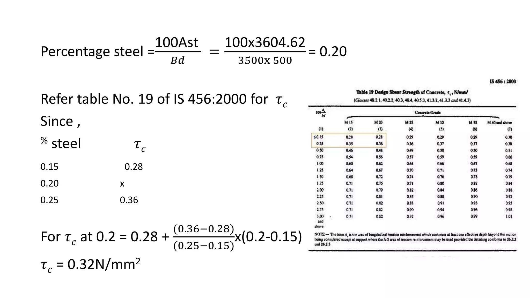
![𝜏v is less than 𝜏 𝑐, design is safe against one way shear.
8) Check for two way shear :
The critical section is taken at a distance
“d/2” away from the faces of the column
Shear force per m,
Vu = p x [A-(0.4+0.5)2]
= 148.16 x [12.25-(0.4+0.5)2] = 148.16x 11.44
=1695kN](https://image.slidesharecdn.com/isolatedfootingdesign-191223115217/75/Isolated-footing-design-35-2048.jpg)