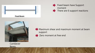
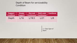
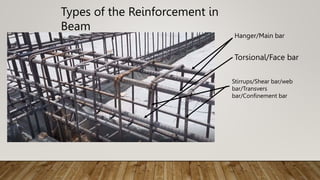
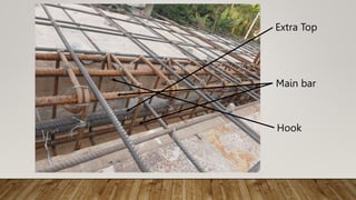
Presentation on Slab, Beam, Column, and Foundation/Footing
1. PRESENTATION ON COLUMN
CE-4104 Building Design Sessional| 2024
Suman Jyoti - 191125
• Department of Civil Engineering
• Dhaka University of Engineering & Technology, Gazipur
Prepared by:
2. Prof.Dr Mozammel Haque
Professor
Mr. Kazi Abu Manjur
Assistant Professor
• Department of Civil Engineering
• Dhaka University of Engineering & Technology, Gazipur
3. • Definition of column
• Size of the column
• Types of column
• Types of the reinforcement in column
• Minimum longitudinal bars of column
• Reinforcement in column
• Failure modes of column
• Column splices
Contents
4. A column is a structural element that transmits, through compression, the
weight of the structure above to other structural elements below. In other
words, a column is a compression member.
The governing forces in column is axial force but shear force and bending
moment may exist.
Definition of Column
Column
5. Minimum width of the column should not be less than 12 inch.
h/b ratio should not be greater than 2.5
Minimum dimension will be 20 times the main bar dia in beam.
Size of the Column
6. 1. According to the dimension ratio:
i. Long column ( L/b > 10 )
ii. Short column ( L/b ≤ 10 )
2. According to the shape:
i. Square column
ii. Rectangular column
iii. Circular column
iv. T- shape column
v. L- shape column
vi. X- shape column
Types of Column
7. 3. According to the reinforcement in column:
i. Tied column
ii. Spiral column
iii. Composite column
Types of Column
8. Types of the Reinforcement in Columns
1. Longitudinal Reinforcement
2. Transverse Reinforcement
a. Lateral Ties (For Tied Column)
b. Spirals (For Spiral Column)
9. Minimum longitudinal Bars of Columns
According to BNBC (6.3.6.3) ACI Code 10.9.2
Min. of 6 bars in circular arrangement enclosed
by spiral reinforcement.
Min. of 4 bars in rectangular or circular
arrangement enclosed by ties reinforcement.
Min. of 3 bars in triangular arrangement of ties.
10. Reinforcement in Column
Code specifications for longitudinal bars :
The reinforcement ratio (ρg ) shall be in between 0.01- 0.06
(BNBC- 8.3.5.3)
For tied column, minimum 4 - ∅ 16 mm bar should be used
For spiral column, minimum 6 - ∅ 16mm bar should be used
Yield strength should not be greater than 60 ksi. (ACI code- 10.9.2)
Code specifications for spirals :
Minimum dia of spirals should not be less than 10 mm.
Spacing =
4 𝐴𝑠
ρ𝑠×𝑑𝑐
Spacing should be in between 1-3 inch. (ACI code- 7.10.4)
11. Reinforcement in Column
Code specifications for lateral ties:
10mm dia bar for main bar ≤ 32 mm dia bar
12 mm dia bar for main bar ≥ 36mm dia bar and bundle bars
Spacing requirements:
Minimum of;
i. 16 times of main bar dia.
ii. 48 times of tie bar dia.
iii. Least dimension of column. (ACI code- 7.10.5)
16. PRESENTATION ON BEAM
CE-4104 Building Design Sessional| 2024
Suman Jyoti - 191125
• Department of Civil Engineering
• Dhaka University of Engineering & Technology, Gazipur
Prepared by:
17. • Definition of beam
• Types of beam
• Depth of beam for serviceability condition
• Types of the reinforcement in beam
• Cracking system of the beam
• Hook length
• Lapping
• Cross section of beam
• Cantilever Beam Detailing
Contents
18. Beam : Beam is a structural member which supports transverse
load by resisting against bending or flexure.
Support moment is zero
Solving by equilibrium law
Types of Beams:
19. Fixed beam have Support
moment
There are 6 support reactions
Cantilever
Beam
Maximum shear and maximum moment at beam
support
Zero moment at free end
28. PRESENTATION ON SLAB
CE-4104 Building Design Sessional| 2024
Suman Jyoti - 191125
• Department of Civil Engineering
• Dhaka University of Engineering & Technology, Gazipur
Prepared by:
29. • Definition of slab
• Types of slab
• Thickness of slab
• Reinforcement of slab
• Deflection of slab
• Corner reinforcement
Contents
30. Definition of Slab
Slab is an important structural
element which is constructed to
create flat and useful surfaces such
as floors, roofs, and ceilings. It is a
horizontal structural component,
with top and bottom surfaces
parallel or near so . Commonly,
slabs are supported by beams,
columns (concrete or steel), walls,
or the ground.
Slab
32. Thickness of Slabs
Depth of the one-way Slab considering serviceability (Deflection)
condition: (BNBC:6.2.10)
Supporting
Condition Simply
Both Ends
Continuous
One End
continuous Cantilever
Depth
l/20 l/28 l/24 l/10
Bottom covering
Covering of Slabs
Slab Walls: Minimum Cover, mm
45 mm φ & 55 mm φ 30
35 mm φ bar and smaller 20
36. PRESENTATION ON FOUNDATION
CE-4104 Building Design Sessional| 2024
Suman Jyoti - 191125
• Department of Civil Engineering
• Dhaka University of Engineering & Technology, Gazipur
Prepared by:
37. • Definition of foundation
• Types of foundation/footing
• Tolerable settlement, tilt and rotation
• Area of foundation
• Design of shallow foundation
• Reinforcement in shallow foundation
• Design of pile foundation
Contents
38. Foundation is the part of a structure that is usually placed below the surface
of the ground and that transmits the load on the underlying soil or rock.
Definition of Foundation
Foundatio
n
39. 1. According to the width to depth ratio:
i. Shallow foundation ( b/d < 2 )
ii. Deep foundation ( b/d > 5 )
Shallow foundations are classified into;
a. Strip footing
b. Spread or isolated or pad footing
c. Combined footing
d. Strap or cantilever footing
e. Mat or raft foundation
Types of Foundation
41. Deep foundations are classified into;
a. Pile foundation
b. Caissons or well
c. Cofferdams
Types of Foundation/Footing
42. For isolated pad footing on sand,
Total settlement ≤ 25 mm
Differential settlement ≤ 20mm
For isolated pad footing on clay,
Total settlement ≤ 40 mm
Differential settlement ≤ 20 mm
For mat or raft foundation,
Total settlement ≤ 50 mm
Differential settlement ≤ 19 mm
Tolerable Settlement, Tilt and Rotation
43. Area of footing will be the maximum of the following:
i. A =
𝐷𝐿+𝐿𝐿+𝐸𝐿
𝑞𝑎
′ Here, 𝑞𝑎
′
= 1.33 qa
qa = bearing capacity of soil
ii. A =
𝐷𝐿+𝐿𝐿+𝑊𝐿
𝑞𝑎
′
Note: Self weight should be taken as 6-8 % and the loads are unfactored in case
of area calculation and factored load for strength design of reinforcement.
Area of Footing
44. DESIGN OF SHALLOW FOUNDATION
Foundation Design consideration:
i. Bearing capacity of soil
ii. Settlement of soil
Factor of safety should not be in between 2.5-3.5
Punching shear should be checked at d/2 distance from the face of column
Beam shear should be checked at d distance from the face of the column
Moment should be taken at the face of the column
Minimum effective thickness will be 6 inch
45. DESIGN OF SHALLOW FOUNDATION
Punching shear strength is = 4 ∅ √f’c ( for square footing). It depend on d/b
ratio.
Beam or one way shear strength is = 2 ∅ √f’c
46. Minimum reinforcement as is as beam = ρmin =
3√𝑓𝑐
′
𝑓𝑦
≥
200
𝑓𝑦
(psi)
Minimum shrinkage and temperature reinforcement, Ast = 0.0018bh
Reinforcement in Shallow Foundation
48. Design of Pile Foundation
Assumptions:
i. Each pile in a group carries equal load
ii. The pile cap is in contact with the ground
iii. The piles are all vertical
iv. Load is applied at the center of the pile group
v. The pile group is symmetric, and the cap is very thick
Design consideration:
The length to diameter ration should not be more than 50 for single pile
Ultimate capacity of driven pile = Qs + Qb –W
Minimum cylindrical strength of concrete for 28 days is 21 Mpa
The minimum area at the butt of pile is 650 cm2 and minimum diameter at
the tip is 200mm.
49. Reinforcement in Pile Foundation
Pile length < 30 times the least width: 1 %
Pile length in between 30-40 times of least
width: 1.5%
Pile length >40 times the least width: 2 %